HOLIDAY DONATION DRIVE - SUPPORT MSW - DO YOUR PART TO KEEP THIS GREAT FORUM GOING! (83 donations so far out of 49,000 members - C'mon guys!)
×


tkay11
-
Posts
1,829 -
Joined
-
Last visited
Content Type
Profiles
Forums
Gallery
Events
Everything posted by tkay11
-
 That's beautifully done, Tomek. I especially like the fact that you can show it with mast up or down. One question: How did you make that lovely little ship's boat Tony
- 17 replies
-
- 1
-

-
- Vistula barge
- card
- (and 1 more)
-
Sorry to have only just caught up with this build. These tartanes are lovely boats. I hadn't realised the Martegao was an allège as I just looked at the name when running through the posts. I can see you've done your research, but just in case you haven't seen the following, I'm putting some suggestions that I found useful in case others would like to research this area as well. There's a good monograph on the allèges by Ancre in English as well as French (both translations from the Italian) which covers their history and has lots of illustrations including some of those by Roux. It also has a set of plans which show the flags and stern coat of arms. What I found particularly interesting was the rigging of lateen sails, and in addition to the plentiful French sources, there's a nice video about traditional lateen sailing boats on YouTube which gave me a good understanding of how the main yard was set up. There are also a few builds of the card model of an allège on this forum (notably Kondzik's), as well as wooden from the ANCRE plans, and a beautiful miniature by Javier Baron, but these differ in some details from the Billings version. I look forward to the rest of the build. Have fun! Tony
- 59 replies
-
- 1
-

-
- Billing Boats
- Le Martegaou
- (and 1 more)
-
To firm up the cardboard, you can also soak the edges with cyanoacrylate glue. Tony
-
Now that's a nice binnacle, George. Very nice. The one you're referring to was in my build of the Chaloupe Armée. The longboat needed a portable one but, as you say, although more experienced modellers made good suggestions, it was beyond my courage levels to undertake. In the end I realised someone may well have just carried a compass in a pocket. Tony
-
Nice way of building those metal knees. Tony
-
@Alex M: All of the model photos I showed from my visit to Chatham were contemporary. The one you linked to wasn't one of them. Tony
-
Sorry, @Alex M. Looking at my photos, if there was a mouse on the Hawke it was hidden by the sails. And I have no recollection of noticing one. An 1820 unnamed cutter clearly did not have one. But a cutter from 1763 did have one, as did the 1790 Trial. Of course, these were just contemporary models and just a tiny sample, which may not be definitive, but it seems the practice varied. Tony
-
@0Seahorse: Another lovely model, Tomek. I just have one question, which you may have answered before with your other models, but I cannot find it. I apologise if I missed it. Could you let me know how you make the effect of grain in your 'wooden' planks lining the hull and on the decks of your other models? You seem to have developed this to a high degree with this model and with Sao Gabriel. Do you print them out simply from a printer? If so, how do you achieve the effect of the wood grain? I know other card modelers have used a foil for this purpose, but you indicate on other models that you just print it, or simply paint. Thanks for any hints! Tony
- 17 replies
-
- 2
-
-
- Vistula barge
- card
- (and 1 more)
-
AAH! OK. I also bought an adapter from MicroMark and imported it from the US along with a couple of zero kerf blades. Thanks for the clarification. I hadn't realised that that's what you meant. Interestingly I have hardly had to use them, using the Proxxon blades instead for all but a few jobs. Tony
-
@bruce d: When I first saw this post, I briefly wondered what you meant by a spacer/adapter. I have used a number of jigs when cutting with the thin slitting saw, but haven't thought of them as spacers or adapters. Could you let me know what you meant? I'm intrigued in case I'm missing a neat trick. Tony
-
Thanks for the information, @Wakha_est. It's good to know about the qualities from a modeller's perspective, and the difference with the coloured versions. I'll think through the options you have suggested. Tony
-
That's great, @Blue Ensign. They do indeed have black hornbeam which they say is now in stock under the title 'coloured hornbeam'. Shipping a bit expensive and I don't know about customs/vat etc, but I'll find out. Pity there's nothing yet in the UK. Very nice suggestion. Thanks very much Tony
-
Does anyone know of a supplier of Black Hornbeam timber in the UK? The regular guys here don't seem to advertise it, other than the normal pale hornbeam. It seems to be commonly used in Eastern Europe by modelers, and it does look very nice! However, I can't find its qualities on the usual searches and so don't know anything about its working qualities. There is some available from the Ukraine on eBay, but I wonder about risking that at the moment. Any thoughts or suggestions, anyone? Thanks Tony
-
@Ondras71: Thanks very much. Excellent video and ideas. Looks like he modified the Proxxon saw table a bit as well. Tony
-
I am intrigued, BE. How do you drill holes at right angles when I would have thought the drill bit alone would be far longer than the space allows? Tony
- 857 replies
-
- 1
-
-
- Sphinx
- Vanguard Models
- (and 1 more)
-
I wouldn't be so hard on yourself, George. It was a very useful book for me as it started me thinking about how to make the kit better. This led to very good discussions with others who were building the Sherbourne. As you say, whether, with hindsight, there are things you'd like to change, it is a guide for the beginner, and the only one I know of that puts it all together in one piece. Tony
- 10 replies
-
- 4
-
-
- Sherbourne
- Jotika
- (and 5 more)
-
Very neat! Slow and steady wins the race, something I'm learning for myself. Tony
-
Very neat work throughout, George. Lovely to follow. Tony
-
Pieds and pouces, anyone? Converting those from the French to anything is another concern. The Ancre publications refer to both metric and ancien when providing measurements. If you use CAD, though, it's fairly simple to draw the plans at full size in whatever measure, then reduce to whatever scale needed and then take the measurements off those plans using either metric or imperial. CAD doesn't yet do pouces and pieds, though. How about the length of one of the mediaeval kings arms or feet, though? That might prove fun. Tony
-
George, I remove the cellotape before gluing. I am using a paper template glued to the deck to make sure the planking is correct, and as the paper is only 0.13mm thick the final result is only just over the ideal 0.5mm. I had the idea from Frolich's book on the Art of Ship Modelling, but had forgotten it until a few days ago. Tony
-
You're right, wefalck. I've discarded card as an idea (I suppose I could have just said I've discarded). I've found I can cut and form these planks using individual plank templates and a cellotape backing to prevent splitting. It's a bit fiddly and takes a long time, but that's the essence of the hobby. And the enjoyment if it turns out ok! Thanks for the continued thinking! Tony
-
Thanks, George. I agree totally with the sentiment. I, too, often go beyond scale, especially with ropes -- as I will on this model should I ever get the masts up. All the same, I am treating this model as another way to learn about handling wood and how far I can go in following scale and plans. I may well discard it once the hull is finished. The problem is that the edges of the waterways go right to the edge as the deck has no bulwarks other than at the bow. They are the same thickness as the deck planking. The real scale thickness is 0.5mm. However, as you suggest, I am tinkering with the idea of going ahead with 1mm, and sanding that down a little in the recognition that few would ever notice that the scale was not correct. None of my family would ever look at plans, as they would just appreciate the lines of the ship, which is pretty much what I like to do. My next option is to print on cream-coloured card, though I don't like the fact that it doesn't look much like wooden planking (even though it is made of wood!). Thanks again for looking in with your usual wise words. Tony
-
Hmmmm! That's something I'll definitely look into, wefalck. I don't have a laser printer, but I can find out if someone else does. Thanks! Tony
-
Thanks, Bob. Very helpful, and thorough in your reply as usual. The trouble I face is that I am trying to stay to scale, and that means that even with the smallest veneer I have (0.48mm) it would still provide a plank 1.8" thick. The plans of the Jacinthe and those of all the other French ships of the same type that I have studied from the period have the same approach to the deck planking. I had considered most of the options you suggest, and I do understand spiling (which I was preparing for), but was worried about the various options that would mean cutting the planks with a scalpel rather than planing the sides, especially with with the rolling taper of the planks which looks as though it is slightly different on each side. I was thinking that might end up without the perfect curves necessary. I am also prepared for edge-bending the planks as I am quite used to that with thicker planks. I haven't yet tried it with thin veneer, though. I certainly can try. In terms of the options, I'd been thinking about preparing the deck flat on a card or paper base (as you suggested and which indeed is the option used by Lloyd McCaffery in his book Ships in Miniature). Lloyd says that for a rolling taper such as the one I have, he uses trial and error, but after having glued several planks together. With my 0.48mm veneer laid on top, I could try this but am still worried about getting the curves right as the curvature seems to differ on each edge of the planks. It may well be that gluing the veneer to the base will help prevent the splitting that I find often with such thin veneers. Another possibility is scribing a sheet of veneer through a mask, but that would require me to buy some wide sheets of veneer, and I would still be worried about scribing it perfectly. Another possibility is printing the deck on to card as do the card modellers, but I have tried that with the Allège d'Arles at the same scale, and couldn't get the paint or card colour to really mimic a wood deck. A very expensive option is to have a sheet of veneer laser-etched, but although I've seen that done on thicker sheets, I'm not sure that that can be done on such thin sheets. What may help is to use a harder wood such as castello or holly. I'd been thinking of lime, but it's harder to cut without splintering. I think, in the end, that I'll just have to experiment a bit, as I nearly always do, and see what I can come up with. I have learnt to work through imperfection and some day it might come out right! Thanks again for your vast experience and helpfulness! Tony
-
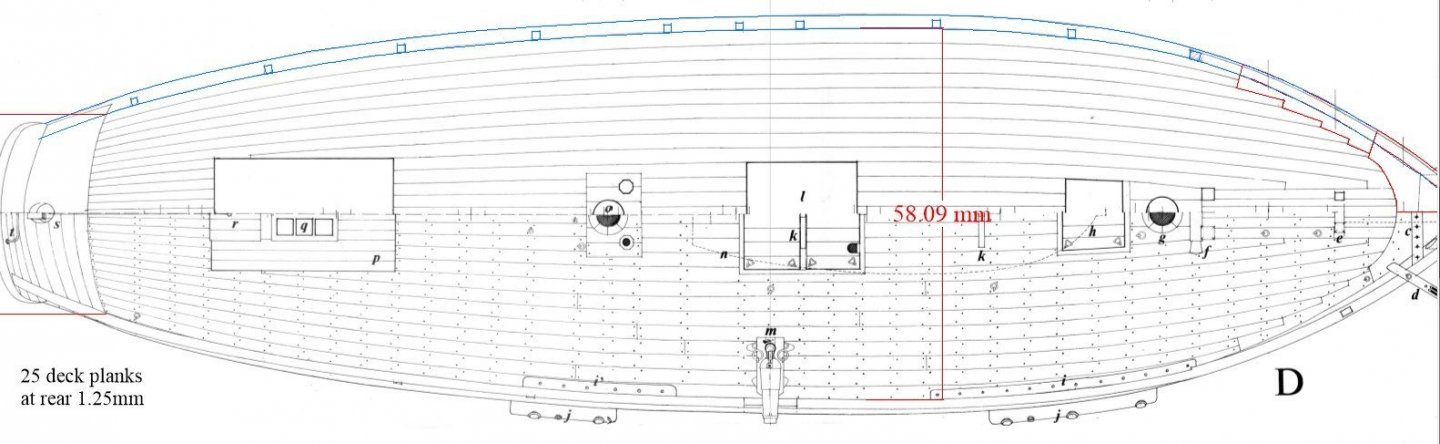
I continue to experiment while learning the art of scratch building. The latest stage is figuring out how to taper and size deck planking that is curved to the lines of the hull, as in the following diagram from the plans of La Jacinthe at a scale of 1:96. I can see that from the middle to the stern it might be a simple job with a plane, but the taper does seem to be variable, thinning mostly at the stern where the planks go down to 1.25mm width. The same goes for the forward end where the nibbing of the planks makes it more complicated. I don't want to waste a lot of wood with endless imperfections, so would be grateful for any suggestions or hints from those with experience of doing this. I have seen many examples of this in build logs, but none that have explained the technique of doing it. Thanks in advance for any help, Tony