HOLIDAY DONATION DRIVE - SUPPORT MSW - DO YOUR PART TO KEEP THIS GREAT FORUM GOING! (83 donations so far out of 49,000 members - C'mon guys!)
×


tkay11
-
Posts
1,829 -
Joined
-
Last visited
Content Type
Profiles
Forums
Gallery
Events
Everything posted by tkay11
-
 Styrene is something I would like to try. The results are really good. Thanks for this wonderful work! Tony
 -
Very nice! Tony
-
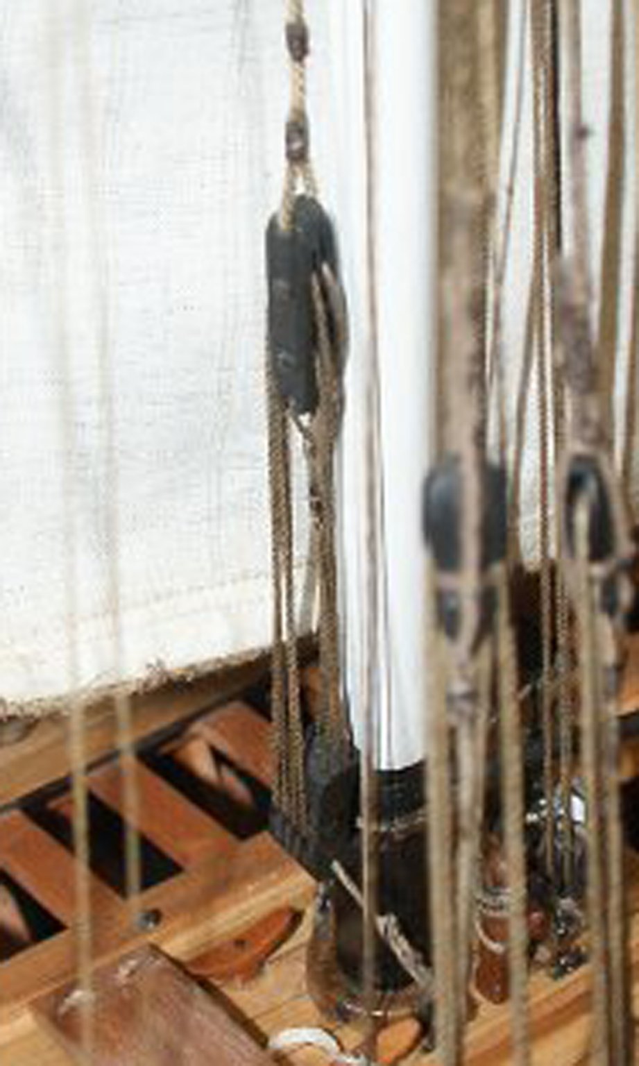
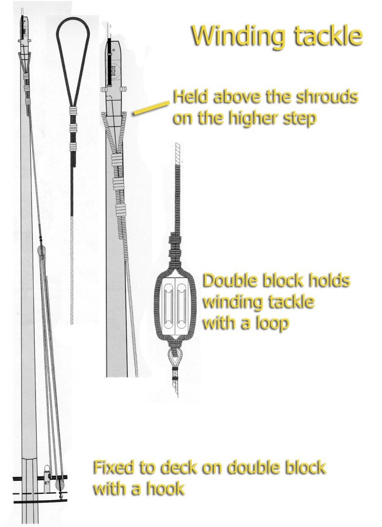
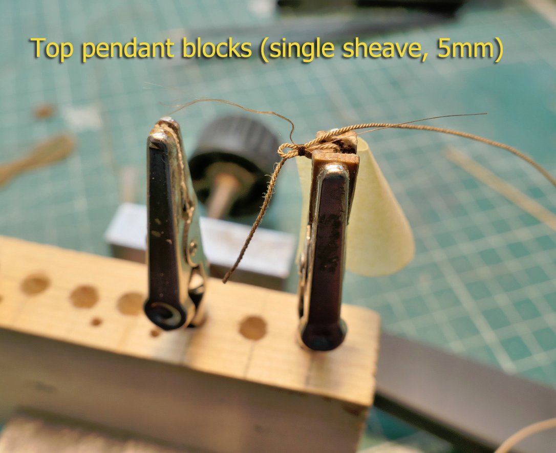
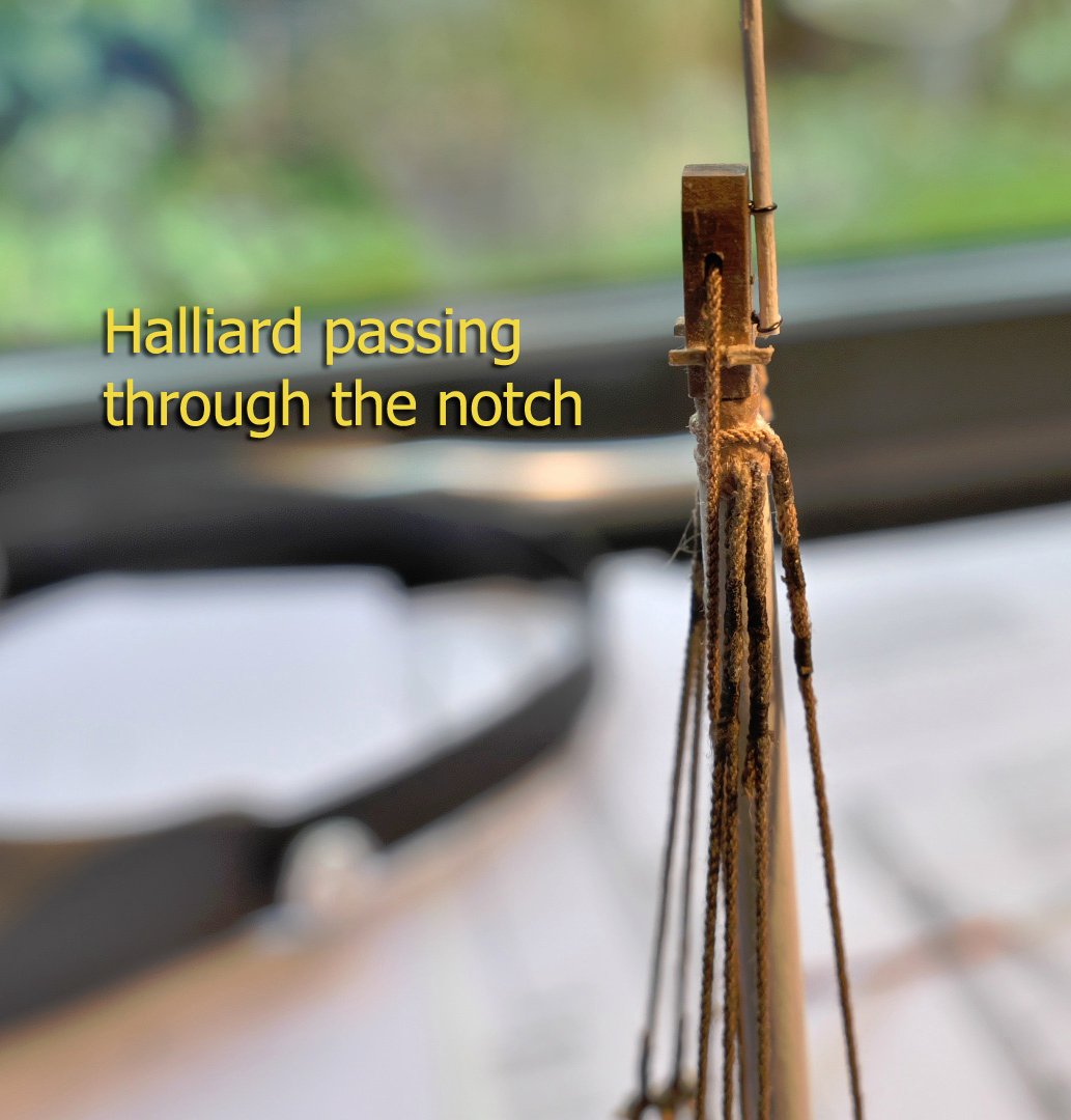
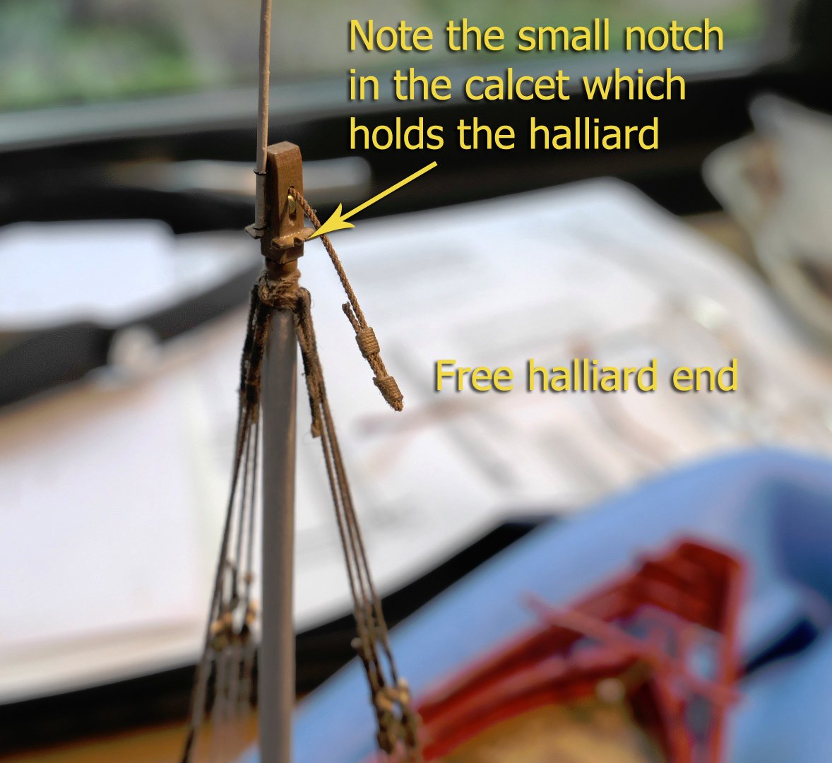
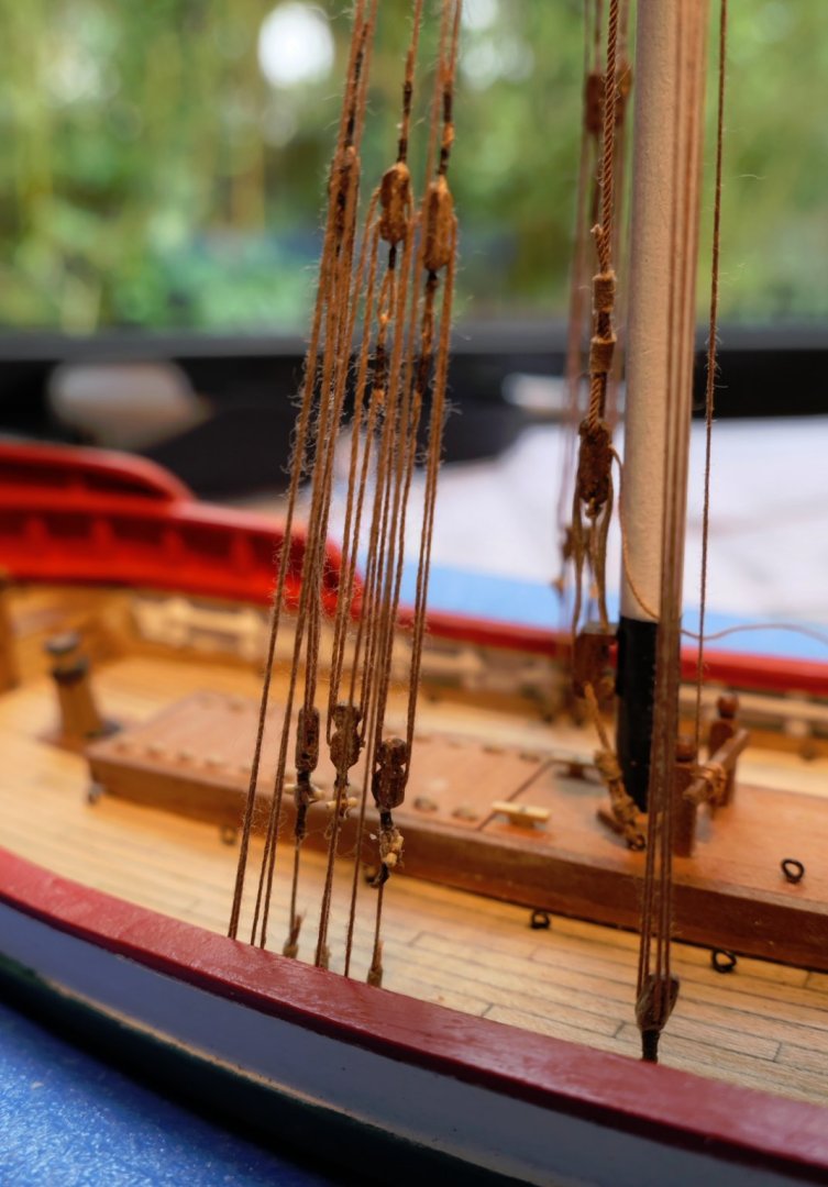
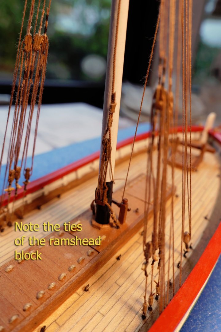
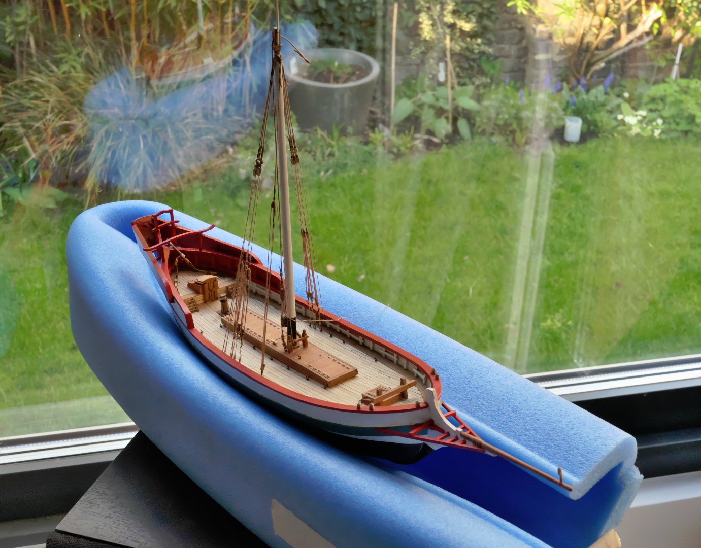
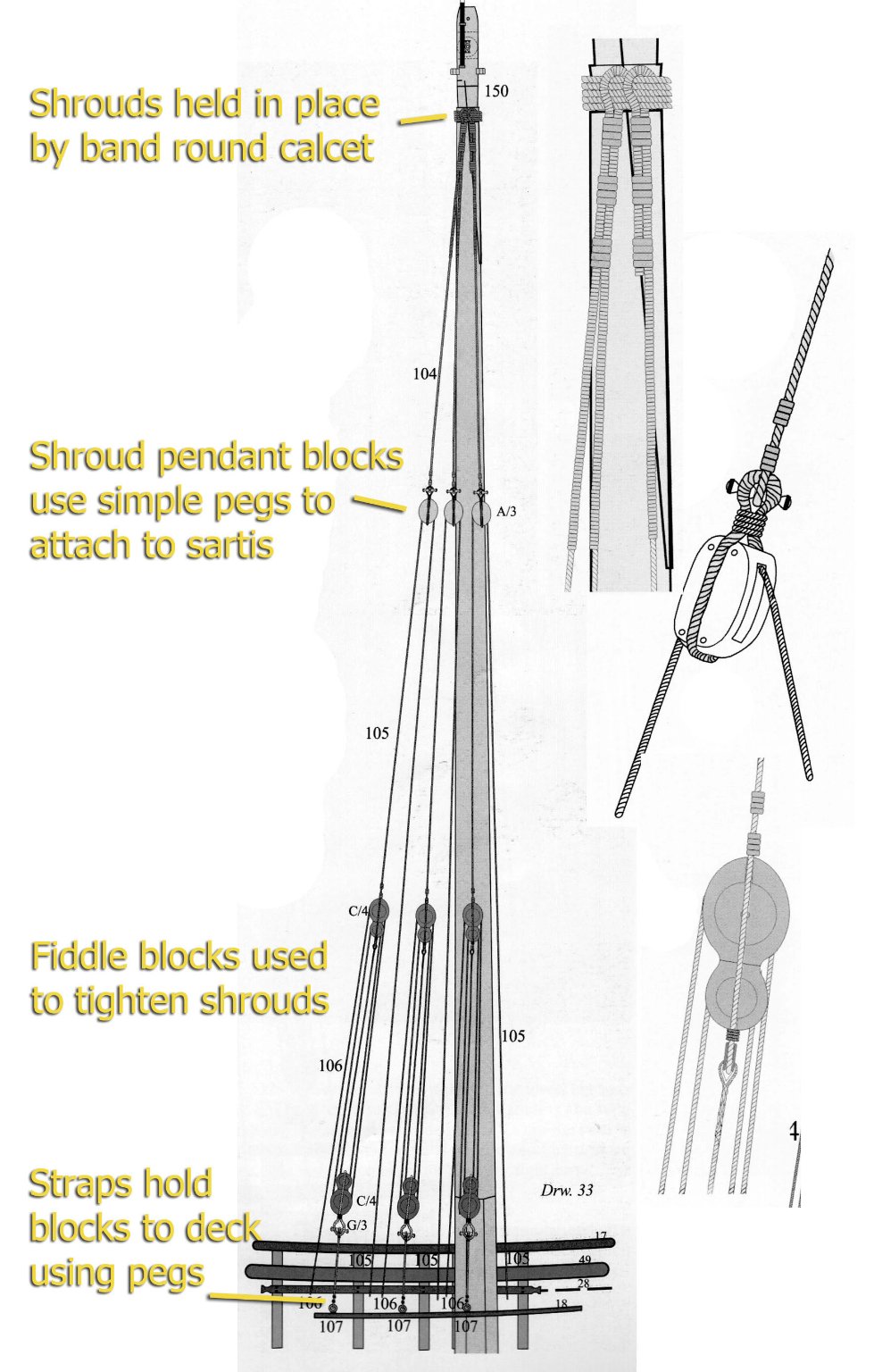
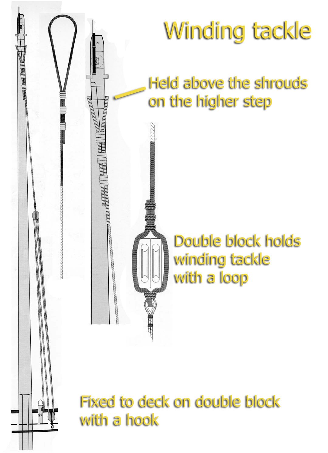
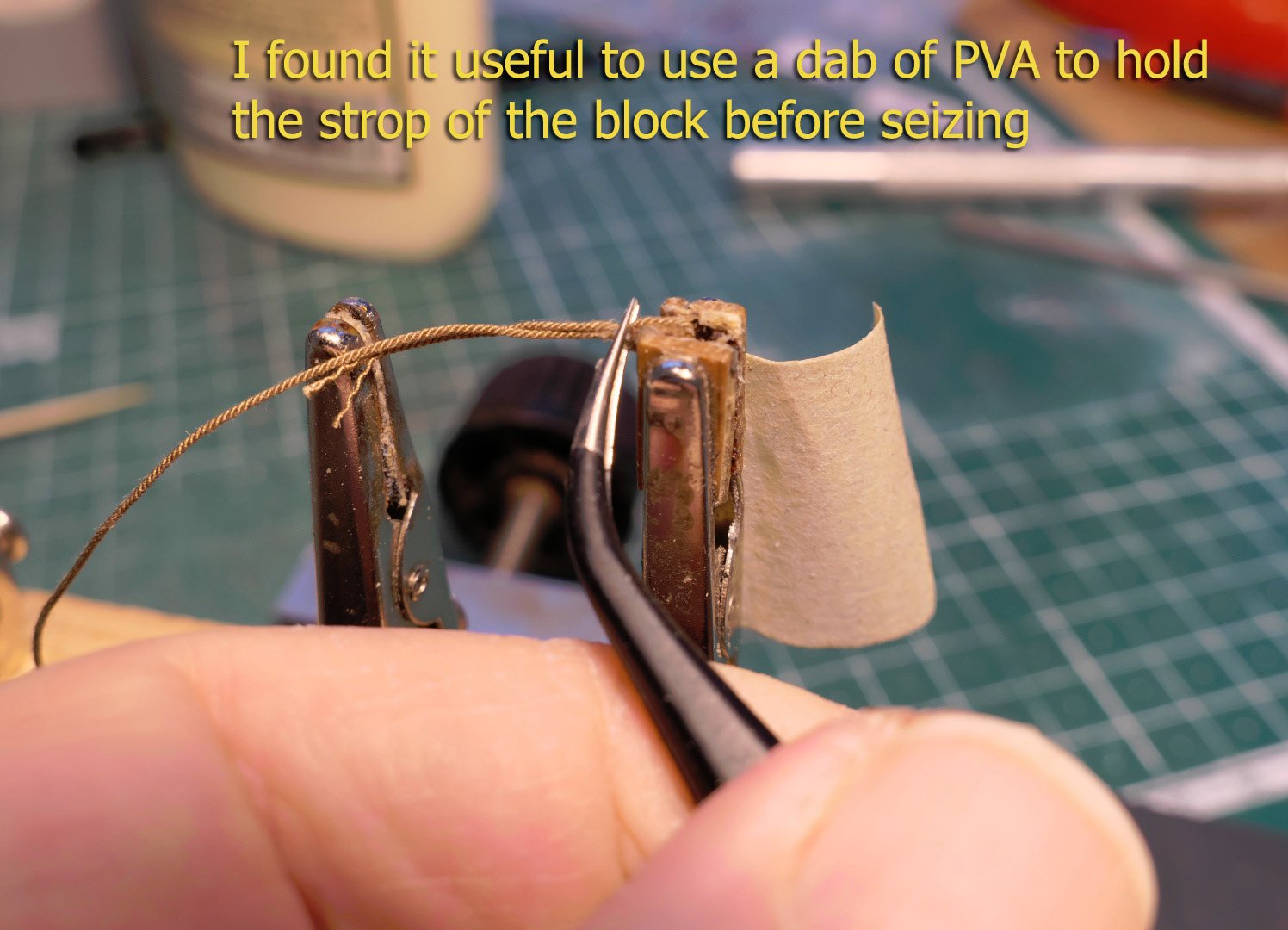
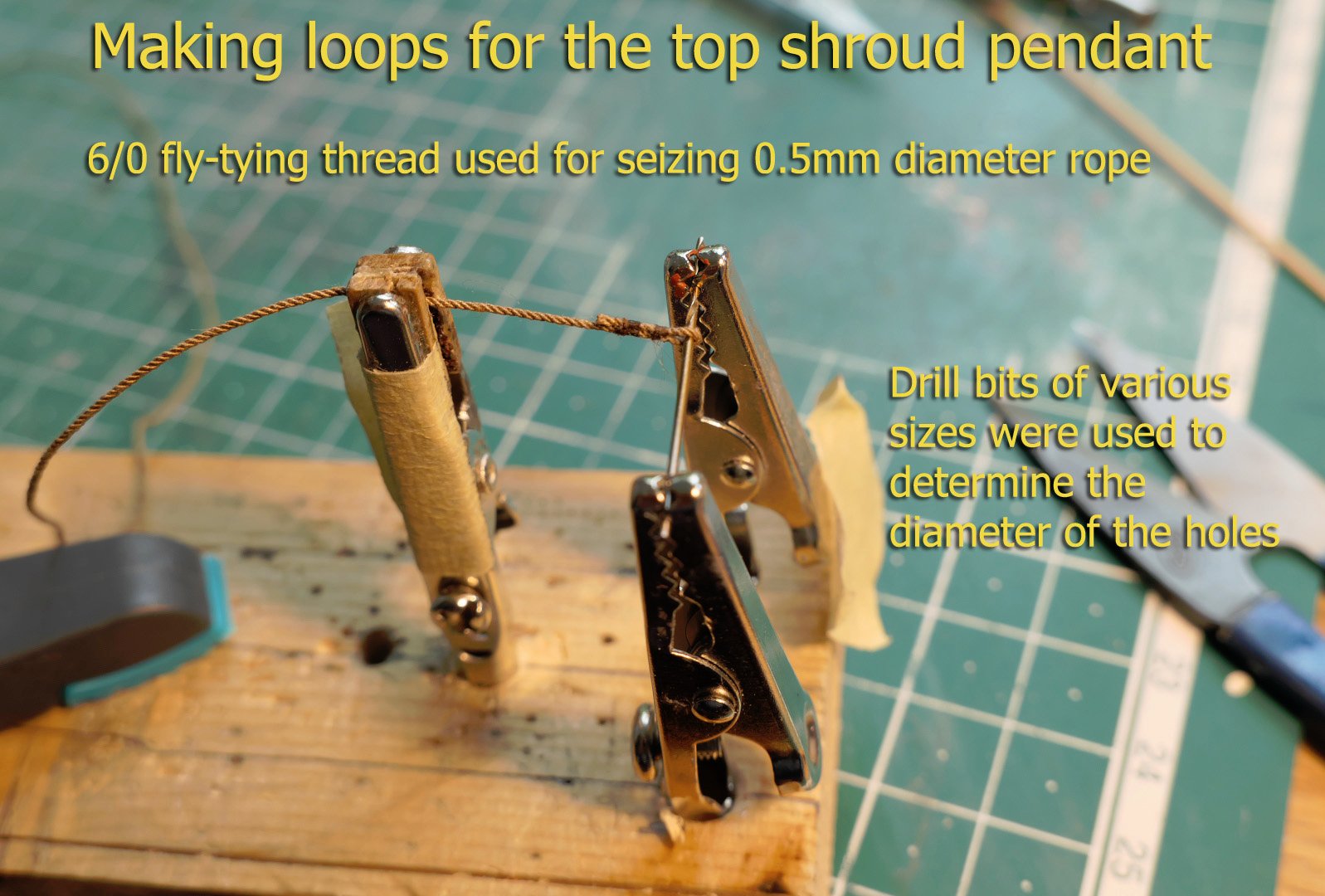
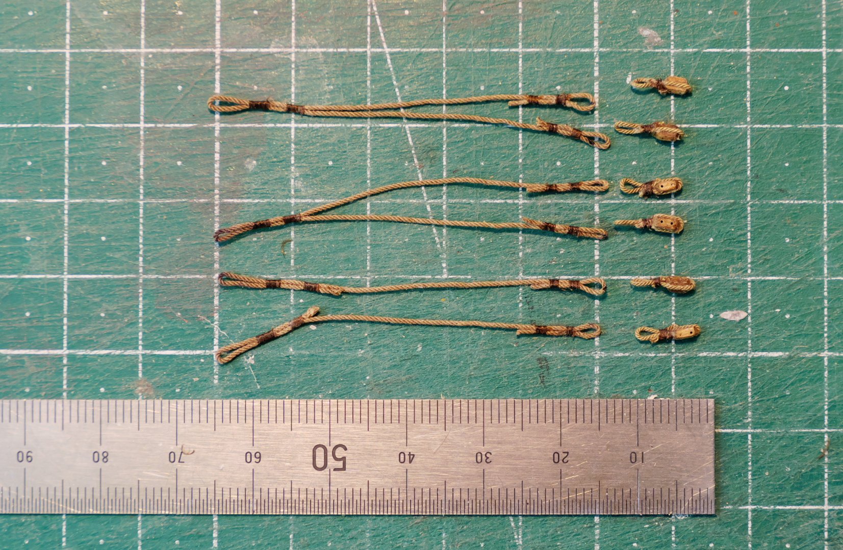
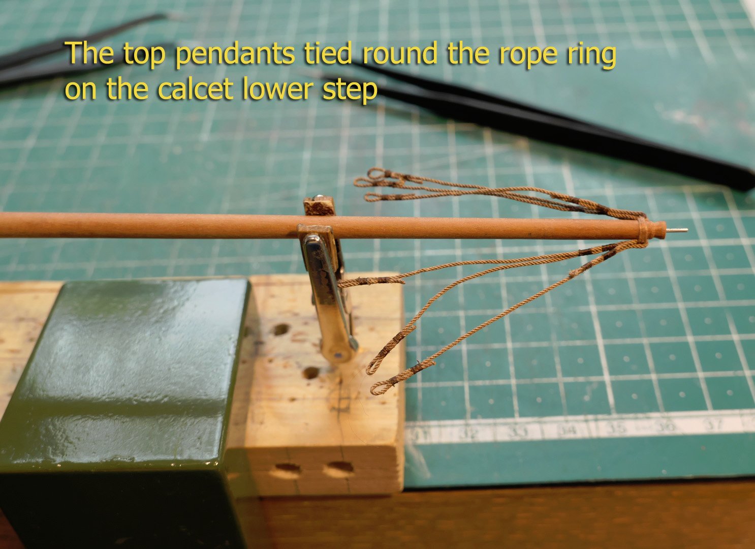
Whenever I look over at the log of @giampieroricci in his build log of La Venus at a scale of 1:96, I shudder at the thought of presenting my own build of a much simpler vessel at about the same scale. It shows me just how far I have to go in terms of skill and workmanship. However, as I’ve said before, I have to learn before I can do; and this log is definitely aimed at others who like myself are just starting model making, and who may like to follow the detailed steps of my learning. The main issues for me are the shaping of very small pieces, and, as you will now find out, my need to improve on rope-making and finish at this scale. ROPE The shrouds, at least, have for most of their construction, a rope diameter of 0.5mm at this scale, making it easy to produce shroud-laid rope with existing threads. However the smaller ropes required rope of 0.2‑0.3mm and so for that I went with ordinary cotton thread for the 0.3 size, and DMC Cordonnet 100 Off‑White thread for the 0.2. For the smaller seizings I used Uni‑Thread 6/0 Waxed Fly Tying Thread. Walnut crystals dissolved in water with a dilution of 1:30 were used to dye the thread. What I didn’t do, and should have done, was to ensure that the fluff of the cotton thread was removed. I only noticed this too late when photographing the rigging in close-up. I console myself by saying that at standard viewing distance it is not really noticeable, especially when the rest of the build is not exactly perfect. Perhaps I should try polyester threads in future. SARTIS I was puzzled by the use of the word ‘sartis’ in the monograph when referring to the shrouds, as may some others when reading the monograph. So, just in case anyone is interested, I did a bit of research. The word derives from the Italian ‘sarte’ or ‘sartia’ which means ‘shrouds’, from the verb sartiare, meaning ‘to rig’. As the monograph is a French translation of the original Italian, this is not surprising. However according to the Glossaire Nautique Répertoire Polyglotte De Termes De Marine Anciens Et Modernes, by A Jal (1868), it was also a word used in a number of ways to define the rigging of a lateen sail in 19th century France, mostly in Provence. This could refer just to the pendants hanging from the calcet, the pulleys at the base of the pendant, the falls of the pulleys, the strops at the base of the shrouds, or the entire length of the shrouds. The particular usage that applies here is not clear in the monograph, as on the diagrams it is used variously, I’ll just refer to the shrouds. SHROUDS Back to the model. The layout of the shrouds is shown in the monograph as follows: The key thing to notice is that the top pendants hang from a ring of rope on the lower step around the calcet, rather than going round the mast. Fiddle blocks are used to tighten the shrouds, and these are fixed to the deck by straps going through ring hooks in the deck. The fall of the tackle goes to the bars on the inside walls of the bulwarks. Another thing to note is that the top pendant blocks are attached to the pendants by simple wooden toggles, as are the straps to the bottom fiddle blocks. I thus spent a lot of time making these different components – the time being taken because I made many mistakes with the order of the rigging and so had to un-do then re-do several times. The sequence I finally made is as shown in the narrative below. First were the top pendants. These have to have a loop at either end: one for the rope ring round the calcet, the other for the toggle from the pendant block. The top loop has to have a minimum diameter of 5mm, the lower a maximum of 1.2mm (to receive the loop and toggle of the block). I forgot totally to take pictures of the bottom straps holding the fiddle blocks to the deck, but you’ll see them in the photos at the end of this posting. WINDING TACKLE The winding tackle pendant is fixed round the top step of the calcet, seized, then attached to a double block which then forms a tackle with another block. The fall is attached with a hook to a ring bolt on the deck. The complete setup is shown in the monograph as follows: FITTING THE HALLIARD RAMSHEAD BLOCK Before completing the fitting of the mast, it is important to fit the ramshead 4‑sheave block and its accompanying halliard block, as the ramshead block has to attached to the boards on the hatch covering with a strap. COMPLETING THE MAIN MAST FITTING One of the details I had missed in the plans was the need for a small hole in the calcet protruding rim on either side to hold the halliard in place. I also placed the calcet in the wrong orientation, as the sheave should in fact run along the axis of the ship and not across. I decided not to try to undo all the rigging and kept this orientation. However, I did cut two notches for the halliard in the calcet, and these are at least functional! The blue foam holder I use while rigging is taken from some old packaging material. You’ll note that the tiller is loose. This is because I removed the rudder after damaging the gudgeons several times when it was knocked by careless handling. Now, with all that done, and after several un-doings and re-doings, I’ll start working on the lateen yard. Thanks again for all the comments and likes! Tony


- 41 replies
-
- 17
-

-
@moab : thanks! I'll shortly be posting the completion of the shrouds and the halliard. I find working at this scale takes a long time, especially with having to take things apart and repeat frequently when I get the order of the rigging wrong! Tony
-
Very neat indeed! The only minor thing I noticed was the needle shaped end of one of the spiled planks. This of course is fine as it will be painted over, but in reality I don't think any plank would have ended at less than half its width. The strake in such cases would be resolved by a stealer or a drop plank. This is covered in the various planking tutorials available on this site. Tony
- 26 replies
-
- 1
-

-
- First Build
- lady nelson
- (and 2 more)
-
That's why eBay prices can go very high, the more so over the last few years; which leads to their cost per cubic metre being much higher than getting castello, and even higher than buying boxwood blanks. Tony
-
In terms just of the rulers which could be one part of the question, some of them clearly state 'BOXWOOD' on one of their faces, especially some of the old Rabone ones which say 'WARRANTED BOXWOOD', and I think every one of those that I have bought are quite different from the others. The trouble is that without that statement they all look alike from the outside because of the varnish coating; but they're still nicefor detailed shaping and cutting with sharp edges. If others know of a better way to spot the difference, I'm all ears. I'm quite happy with castello as it is cheaper and more available, as well as being in almost any size you would want (rulers are very limiting in that respect); but I prefer the look of boxwood and its hardness (not that I'm at all expert with either). Apologies if I've misunderstood the question, which I am wont to do! Tony
-
Lateen halliard blocks - attached to mast?
tkay11 replied to tkay11's topic in Masting, rigging and sails
Thanks, Gérard. I thought that might be the case. but just wanted to make sure. It'll also make it far easier to rig! Tony -
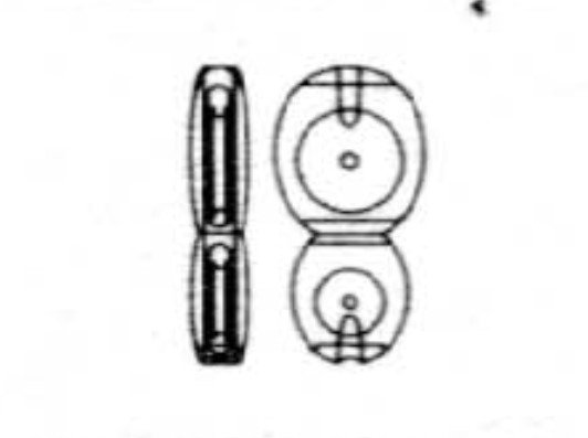
Just as a matter of interest, I was wondering whether the 4-sheave halliard blocks of some lateen rigs were attached to the mast or just held there by the force of the ropes. The illustration is from the monograph of the Allège d'Arles published by Ancre, and shows the block I refer to. Any answers are welcome! Tony
.thumb.jpg.09bfe396e18433b2e7a62c9b69d793fe.jpg)
-
If you haven't already seen it, you can follow a nice discussion by Bruno of his planning, design and building of the Louise on the Marine & Modélisme d'Arsenal forum at LOUISE - Tentative de reconstitution d'un clipper d'Argenteuil. I look forward with much interest to this build. Tony
- 153 replies
-
- 1
-
-
- Ancre
- Bruno Orsel
- (and 2 more)
-
Thanks again, kondzik. I keep coming back to the question of the type of filler used. I am suspicious of the standard water-based fillers because of the potential for warping paper as well as shrinkage. Do you mean the kind of filler used for cars, one that is mixed from two components like an epoxy filler? Tony
-
That's both helpful and interesting. Thanks very much, Kondzik. I really like your builds, by the way. Tony
-
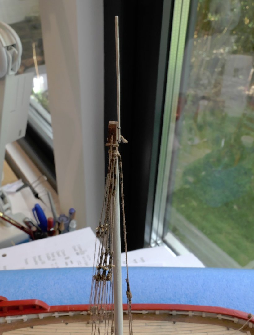
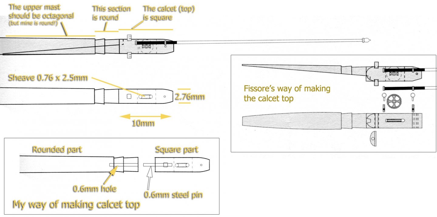
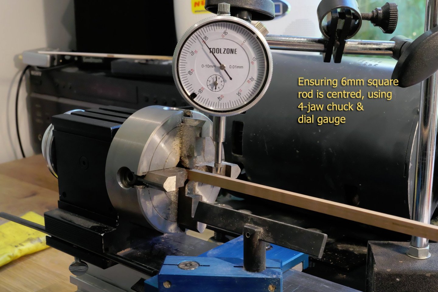
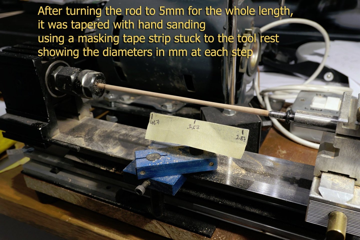
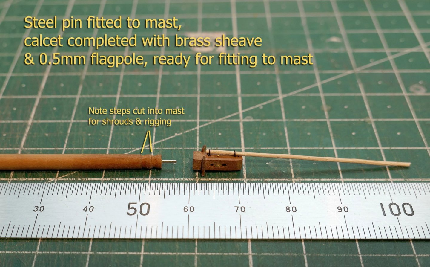
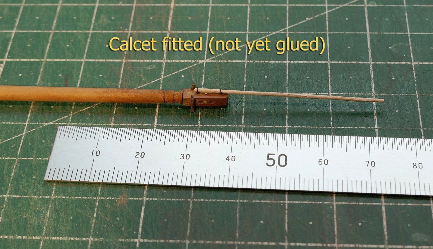
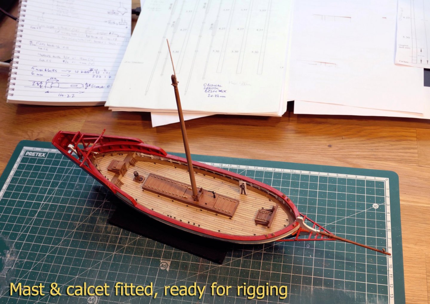
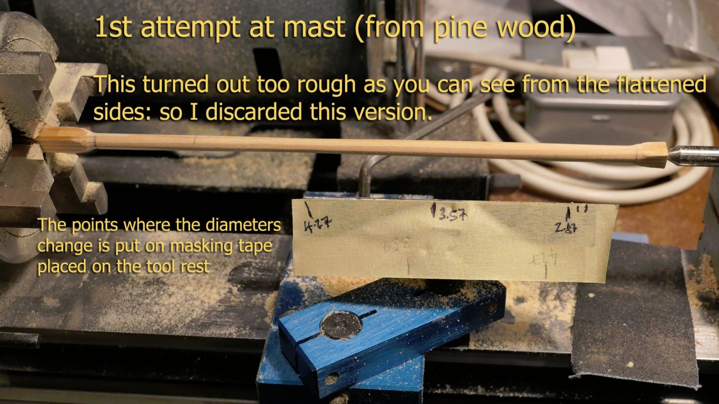
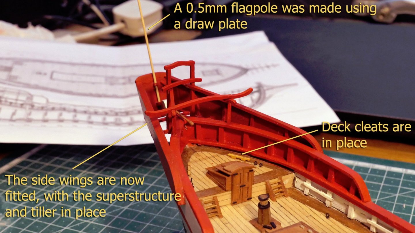
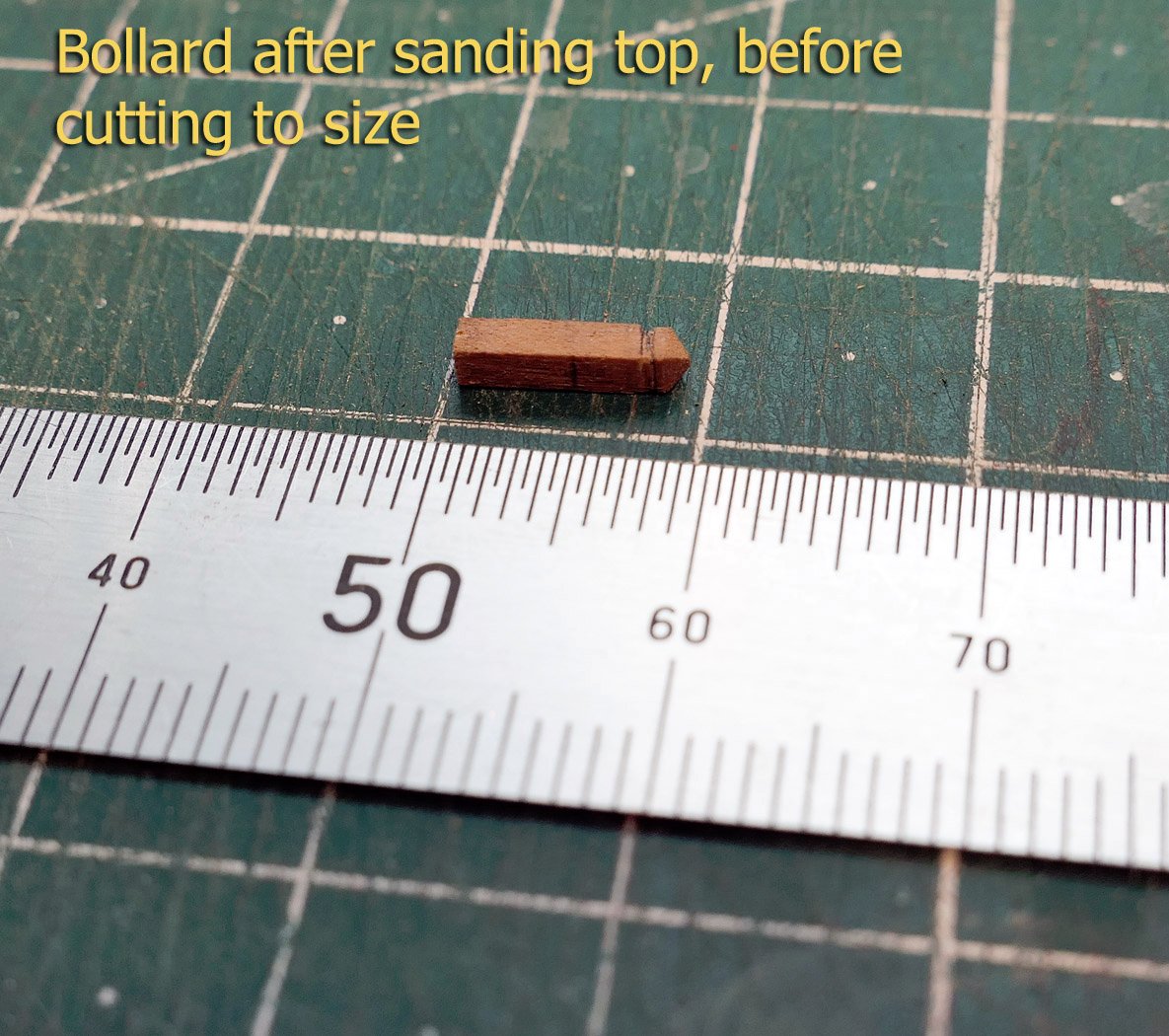
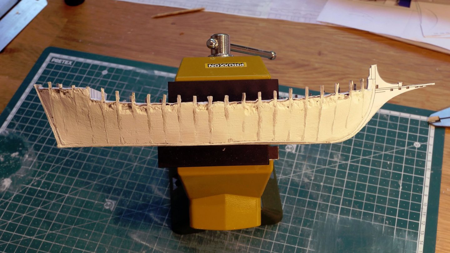
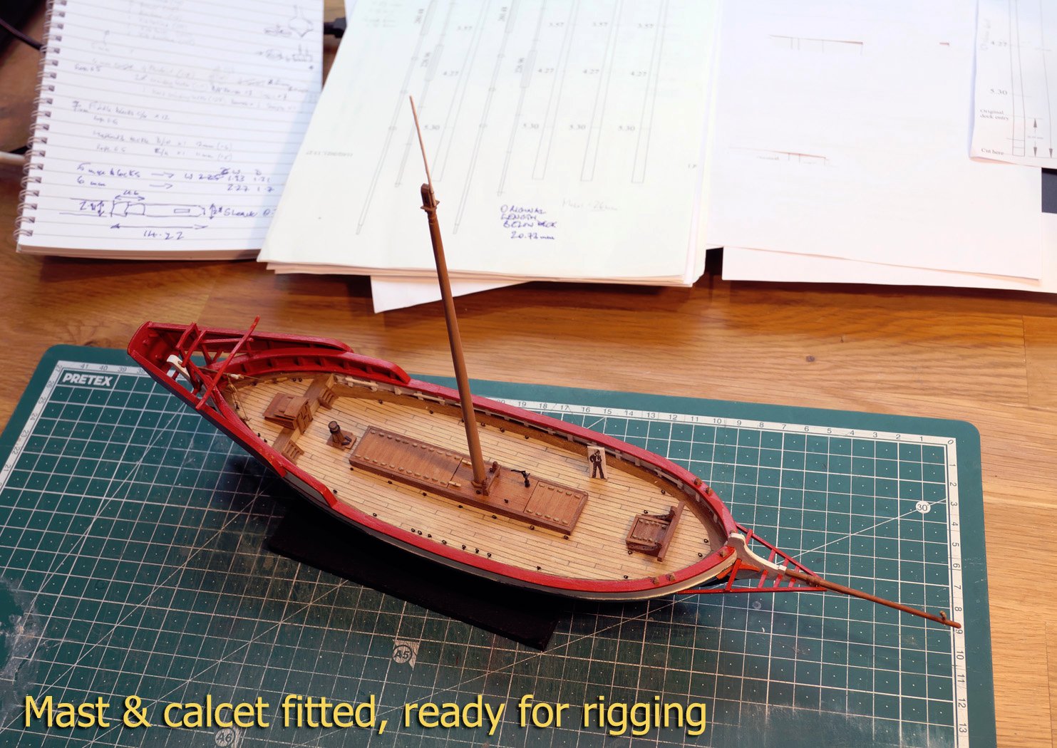
Mast & calcet The calcet, or mast cap, is described as follows in the monograph: Masts with a calcet are similar to those used on Mediterranean galleys. The difference between masts with a calcet and regular masts is in the fact that the former are big and short and carry a lateen yard much longer than the mast, and they have no top. Vessels that carry one or more masts with a calcet are galleys, xebecs, pinques, tartans, feluccas, Provence barks, etc. They are all Mediterranean vessels. The problem for me was that the calcet is 2.87mm square, and this stands on top of a round mast. I couldn’t work out how to turn this easily, as I’d have to start with 6mm square stock for the mast. Fissore’s method is to cut a long diagonal joint at the top of the mast, but that looked way to complicated for me. I decided I go for a simple pin to hold a separate calcet to the mast. My first attempt at a mast was with pine wood. However, no matter how I sanded it, there were still flat surfaces left around the mast, so I discarded it and went for my usual pear wood. I set up the 6mm square pear stock in a lathe and centred it using a dial indicator as shown: I again used the sticky tape to point to the changing circumference of the mast, and, after rounding the mast to a constant 5mm diameter using lathe chisels, sanded it down (from the deck level upwards) to the correct dimensions. I then cut the steps at the top of the mast as shown in the plans diagram above, and drilled the 0.6mm hole in the top of the mast to take the steel pin as described above. Those with a keen eye will note that neither the base of the mast nor the top have octagonal sides. This is quite deliberate as I know if I tried to make them so at this scale the result would look atrocious. After using the lathe to cut the small steps at the top of the mast for the shrouds and rigging, I made the calcet, its brass sheave and the 0.5mm flagpole. The combined mast and calcet was then fitted to the hull. I will now go on to making the yards and rigging the model, which will probably take quite a time. Forgotten addition re bollard Just as a small postscript, I found a spare bollard that allows me to show one before fitting. I had wanted to include such a picture in the earlier logs, but hadn’t taken any photos of one; so this one will be inserted into the relevant log. Thanks again to everyone who is following this build. Tony

- 41 replies
-
- 14
-
-
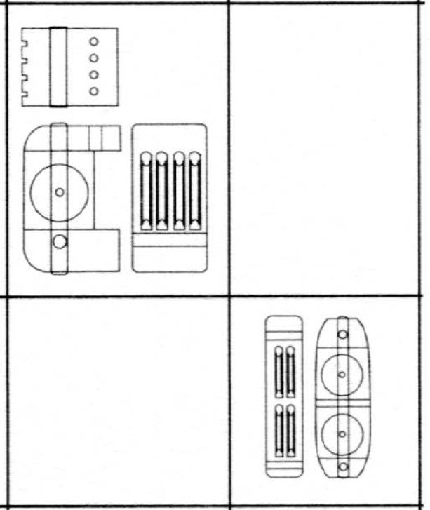
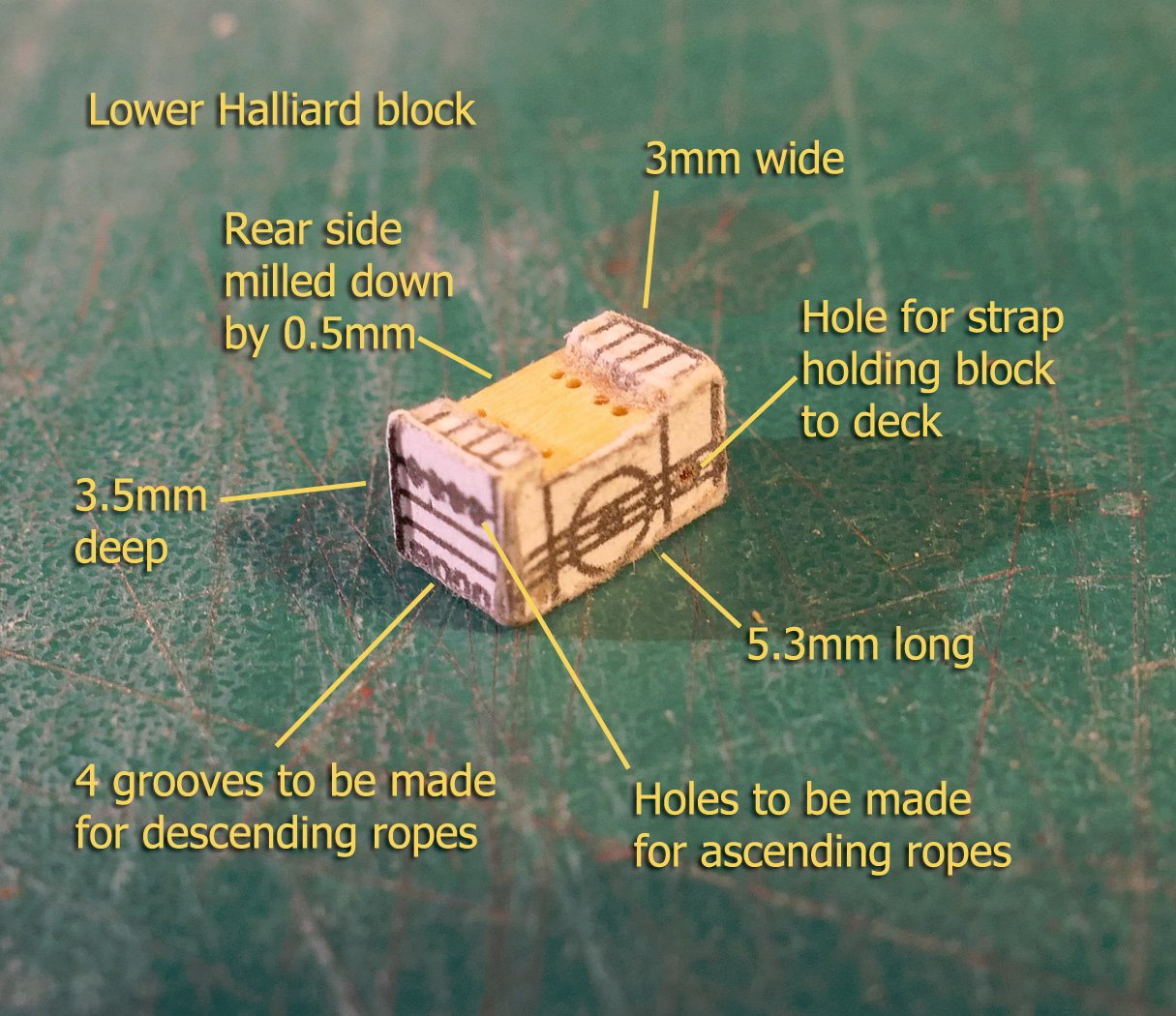
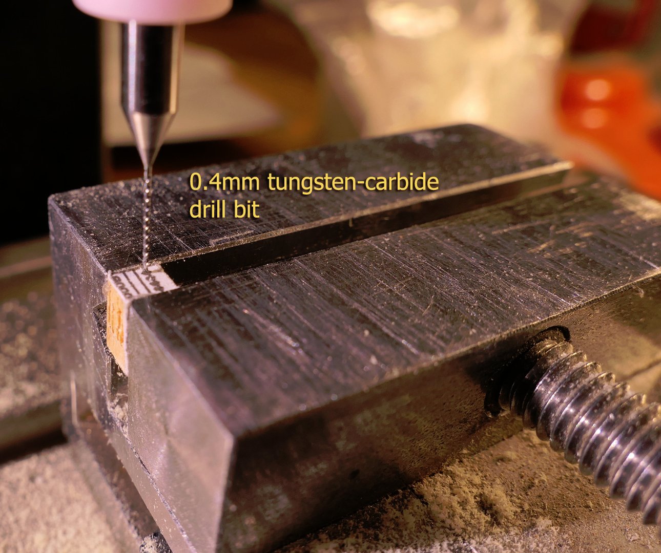
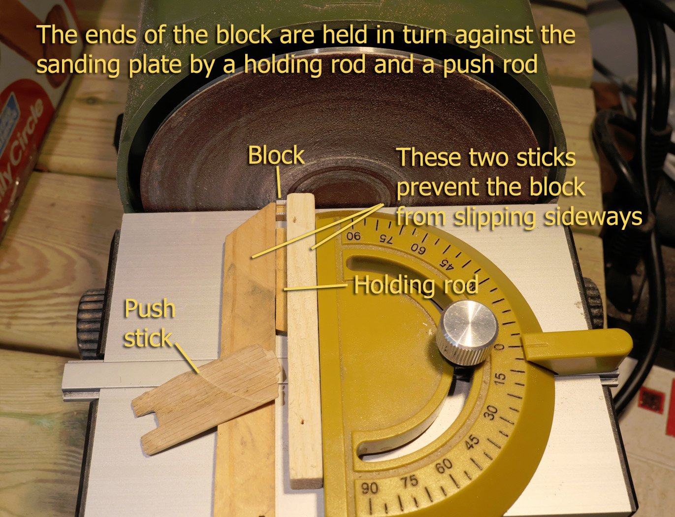
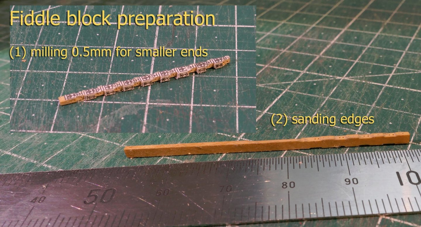
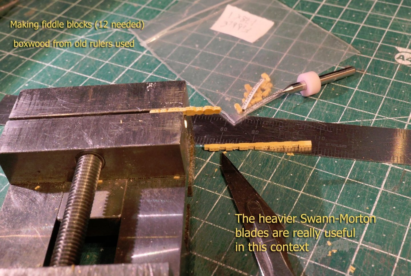
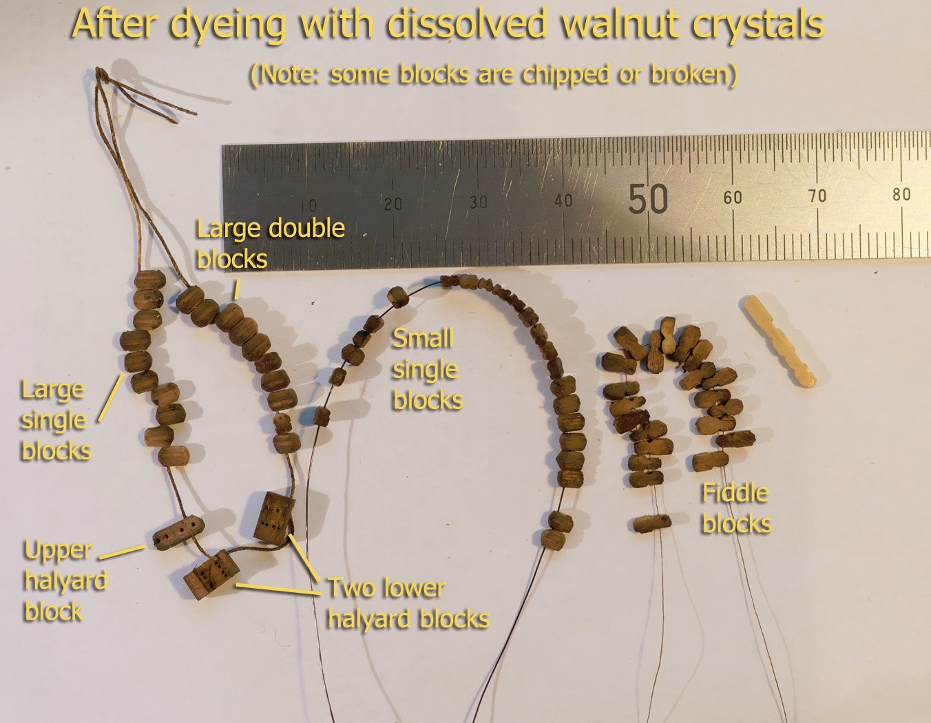
Blocks As mentioned before, I still have a long way to go before I can make blocks below 2mm which look like blocks. At 1:100, the smallest blocks have to be 0.76 x 1.19mm, the next ones up 0.98 x 1.48. So I had to settle for the third size up as my smallest block at 2.27 x 1.27mm. The smallest thread I use that still maintains a semblance of rope is 0.3mm diameter, so I have to use 0.4mm holes in the sheaves as my smallest. The largest rope at this scale should be 5mm, so that’s no problem. However, I’m still thinking about whether to serve some of the 5mm ropes. I probably will. These measurements pretty much dictate the size of the blocks at present, and I still have problems with making them presentable. The blocks for this ship range from a large number of ordinary single and double sheave blocks, 12 fiddle blocks, and two large blocks for the halliard tackle, each with four sheaves each. Halliard blocks Having made the small and large single and double blocks, whose photo you will see later, I started with the two 4-sheave halliard blocks. Although I had made the other blocks from boxwood, these larger blocks I made from castello since their dimensions are larger than my boxwood rulers would allow. The plans show them as follows: Although there is no further detail of these in the monograph, other than the plans, I found it useful to refer to the excellent diagrams available in the Ancre monograph of La Diligente, a two-mast lateen-rig boat of the same type. The plans show them as follows: And Fissore’s build photo shows them as follows: I decided that making sheaves at this scale would be impossible, so I just drilled the holes for the ropes. I started by copying the three sides of the block and pasting them to a boxwood block of the correct dimensions. I then milled out the rear face to a depth of 0.5mm as per the plans. The photo below is of an early attempt and shows that this was a little too small, so I milled to a depth of 0.8mm in later blocks. I then drilled the holes accordingly. As a matter of interest, although the cheap Chinese tungsten-carbide bits are famed for their fragility, once I started using them in the mill I haven't had a single one break. They have a great advantage in being very accurately made. They are so cheap I bought a good range from 0.1 to 1mm, with packs of 10 of those between 0.3 and 0.5 just in case. And then sanded to their end points, using the following way of keeping these small blocks vertical to the drum sander. Once I had rounded the lower halliard block I made the fiddle block in much the same way. Fiddle blocks These hold the shrouds, or sartis, and also required care. You can just make them out in Fissore’s photo of the blocks shown above. The plans show them as: Again I pasted the plans to correctly sized boxwood strips, and milled down the sides of the lower blocks. I then found that using the larger type of Swann-Morton blade (the number 11s were too flexible) was a good way of outlining the edges before a very fine final sanding. The picture shows them before final sanding. Although there has been discussion about the merits of keeping the lovely colour of boxwood as my initial experiments showed the results to be very blotchy, I decided that it would look much better to have them the colour of dark wood, as on other contemporary models of the allèges. So I made up a solution of walnut crystals, and kept them overnight in the solution to ensure penetration of the wood. The result is as follows. As you can see, not perfect, but acceptable to me. I’ll now spend the next few days (maybe longer) making the mast and the calcet, then the yards. Once I have achieved that I’ll post again. In the meantime, thanks again for the further ticking of the likes! Tony
annot.thumb.jpg.1abcf4b46a7e2a5a7821ca0281eb2cfc.jpg)
annot.thumb.jpg.d87320487bc6796c3940911294aebd4b.jpg)

- 41 replies
-
- 11
-
-
That's very nice of you, Edward (I presume). Thanks. It's always slightly embarrassing for me when I compare the work with that of Fissore on his allège (for all the faults with the monograph), or any of the more experienced builders, so it's always nice to hear when someone appreciates my small steps as I learn. I suppose small is the word at 1:100, but then there are really great models at 1:200 and further. Tony
-
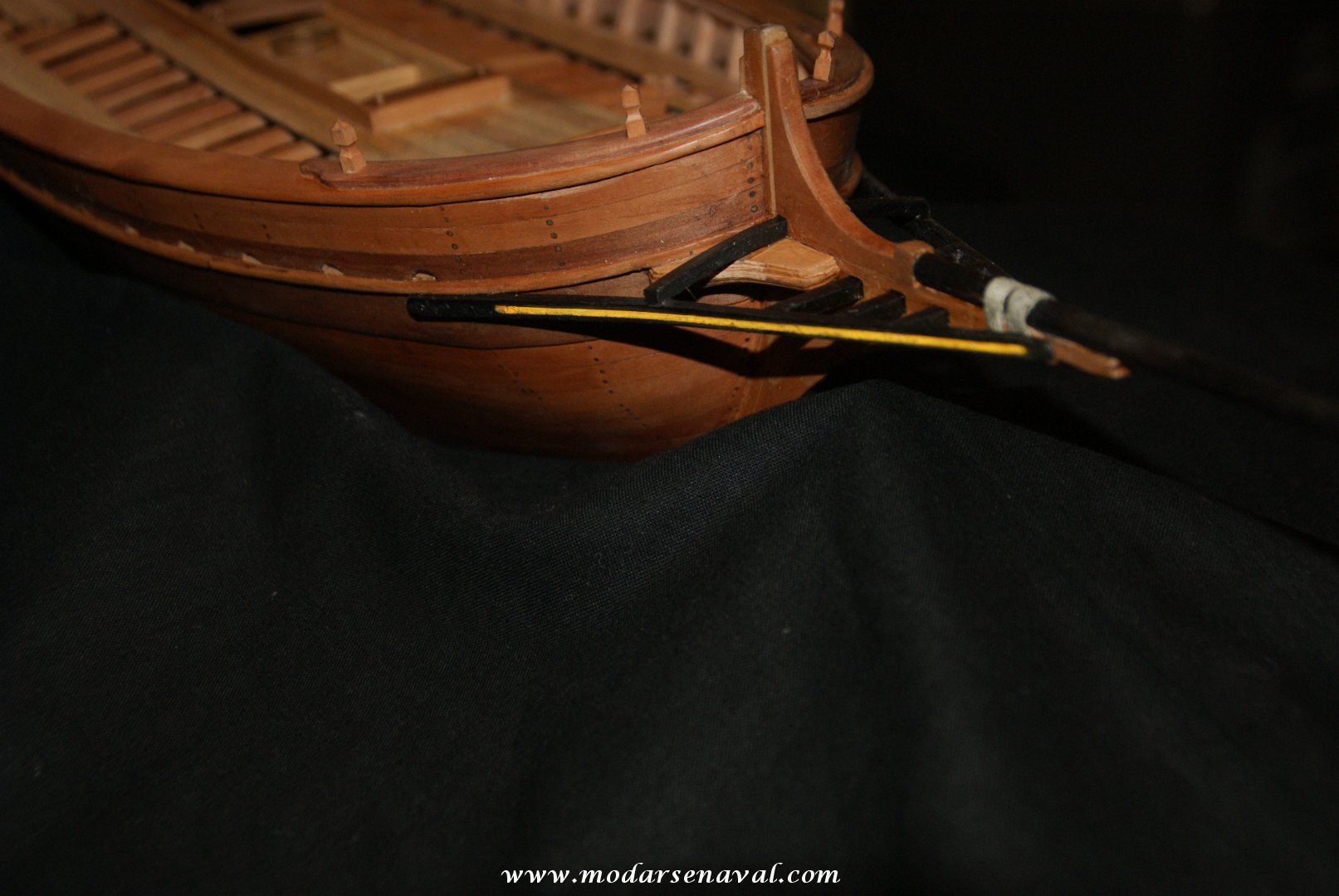
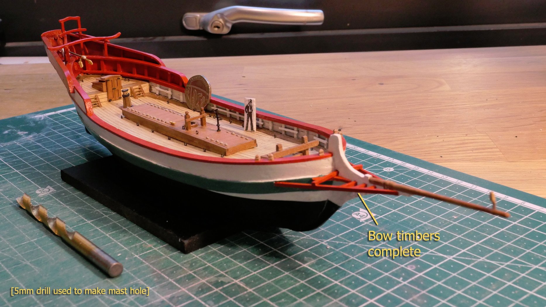
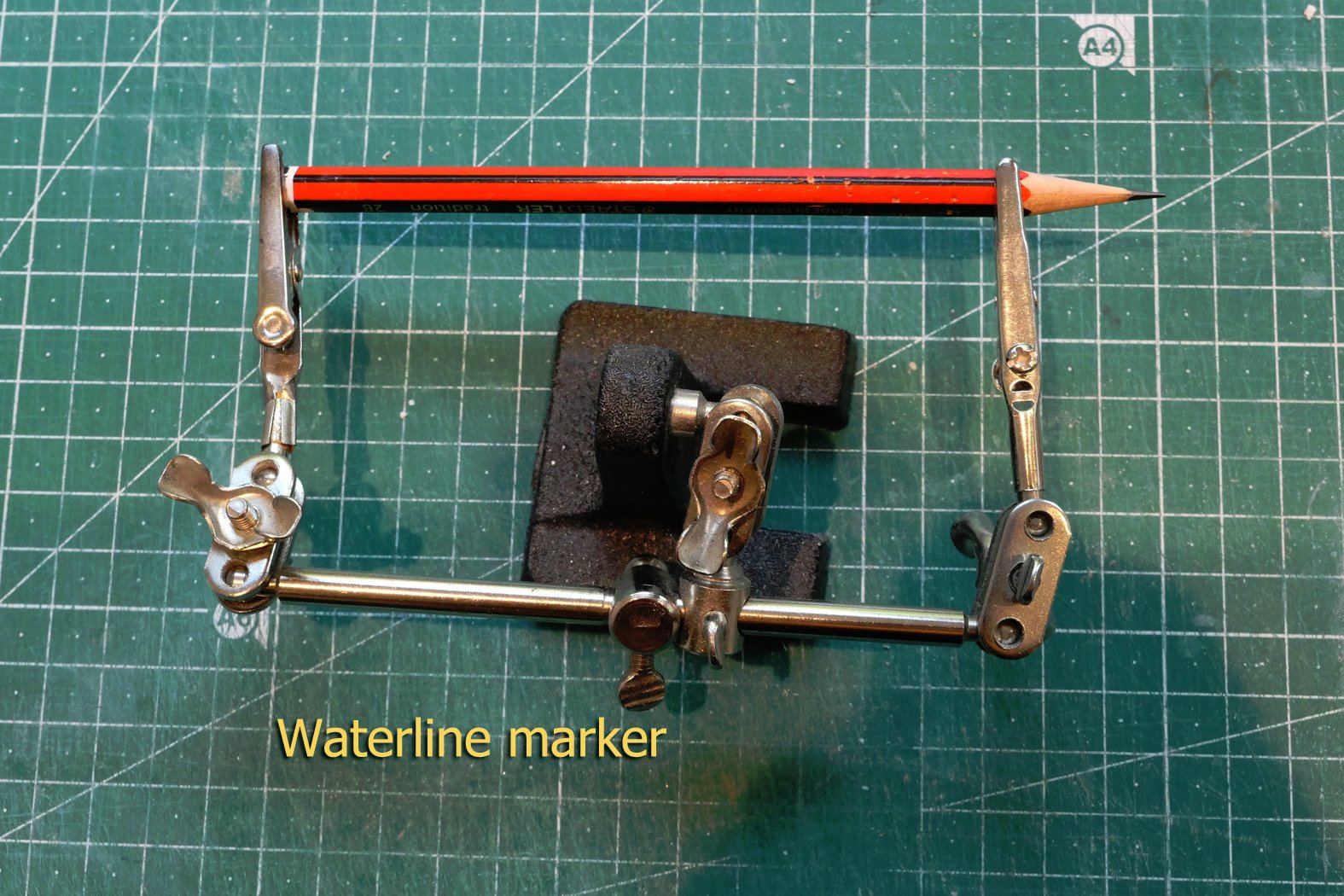
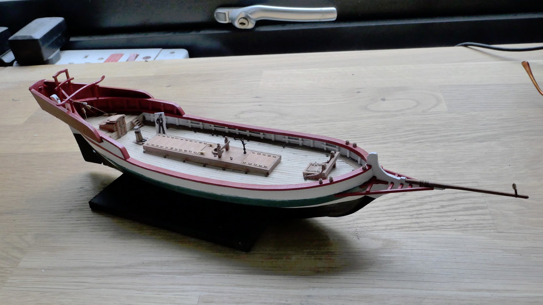
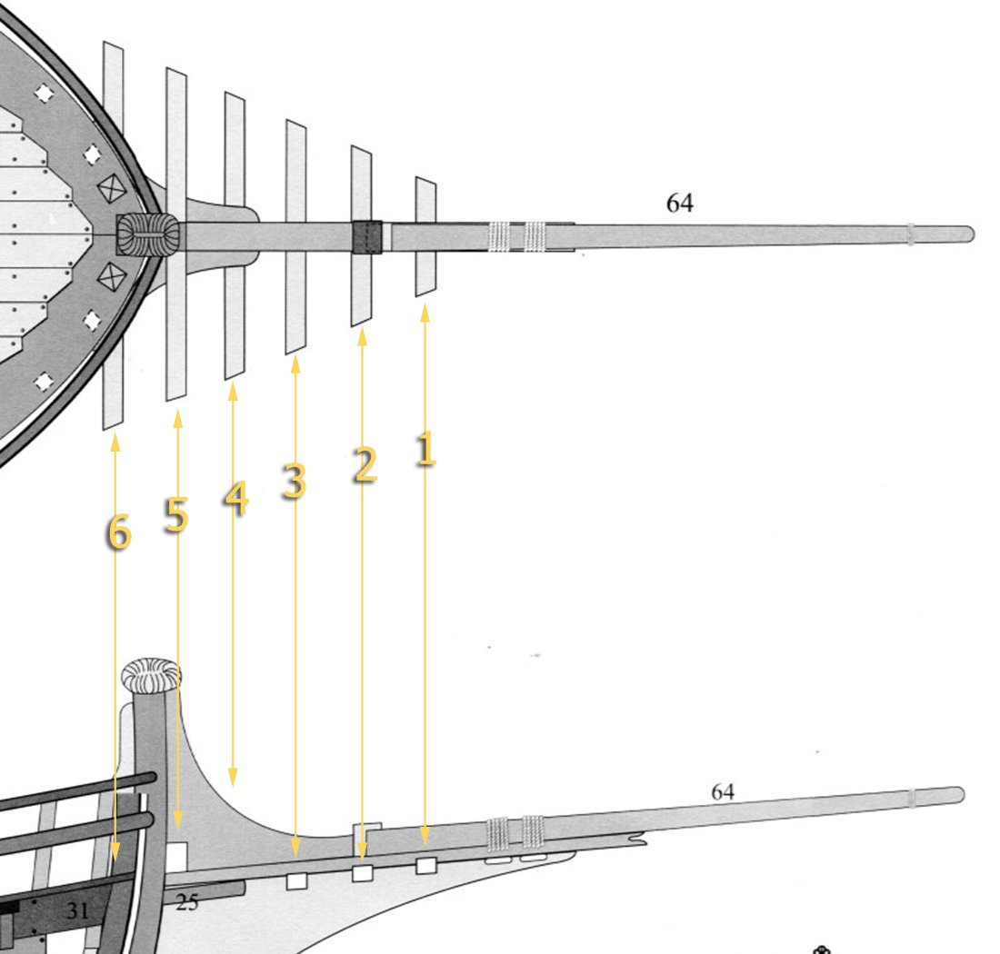
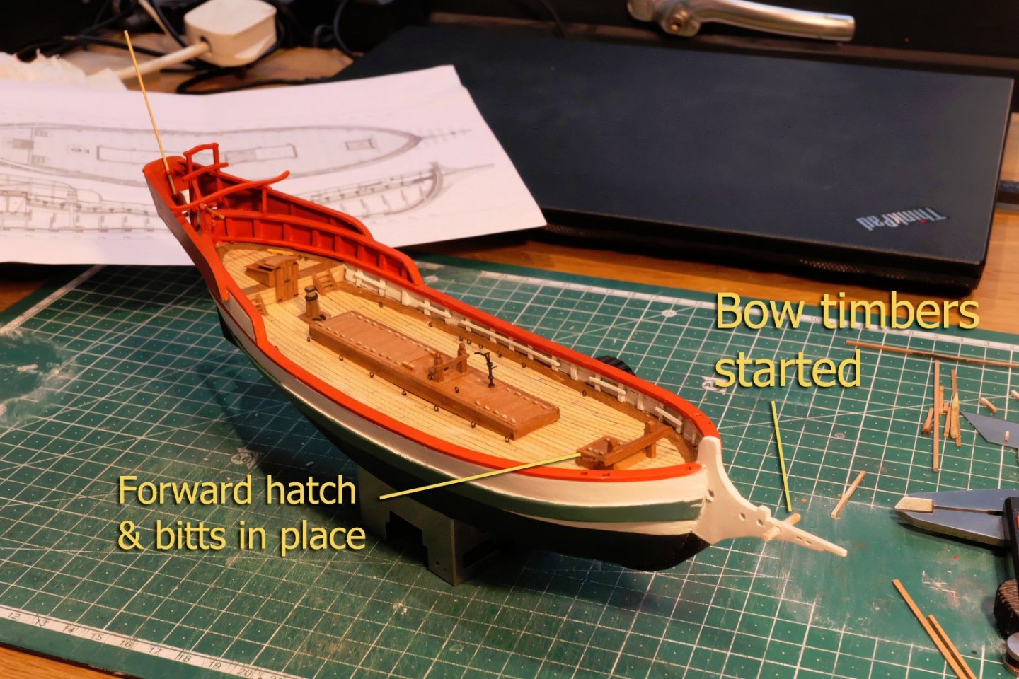
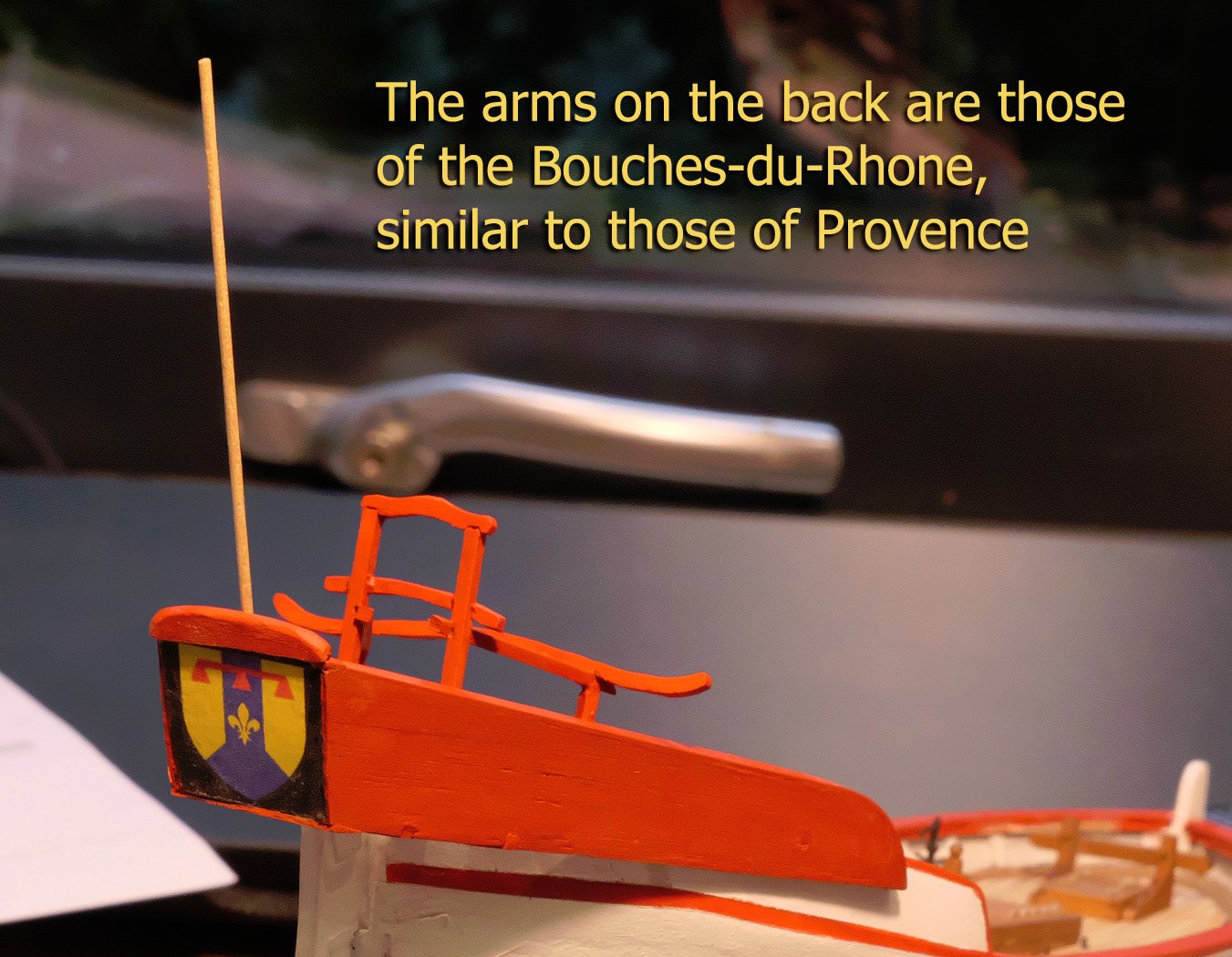
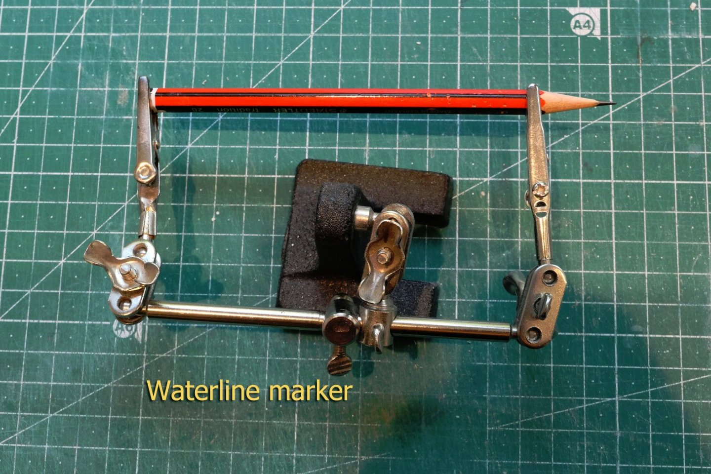
Bow timbers This is where there is yet again variance between the plans and Fissore’s build as shown in his photographs. The plans show 6 cross-pieces, but even on the plans there is a mystery as to the support holes for timbers 4 and 6. Not surprisingly, Fissore shows timbers 1, 2, 3 and 5 only. So, as Fissore chose to ignore the timbers 4 and 6, and given that they are a mystery in the plans, I went the Fissore build route. Heraldic arms The monograph does not mention the origin of the heraldic arms on the rear wings panel. I did some research on this and they are the arms of the Bouches-du-Rhône, indicating, of course, the area covered by the allège. As a last note before I return to doing some construction, here's a photo of my waterline marker. And a little photo of the build as it is in its current state. You'll note I have done the bowsprit and the jib block, and tied the bowsprit to the stem. Next up, a brief note about making the blocks. Tony


- 41 replies
-
- 14
-
-
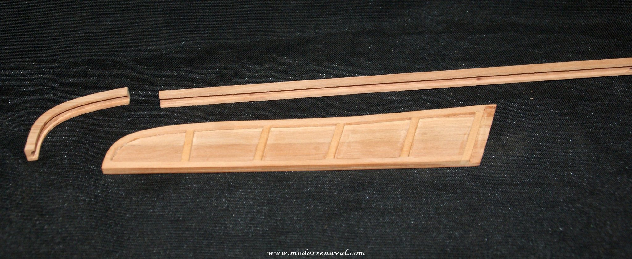
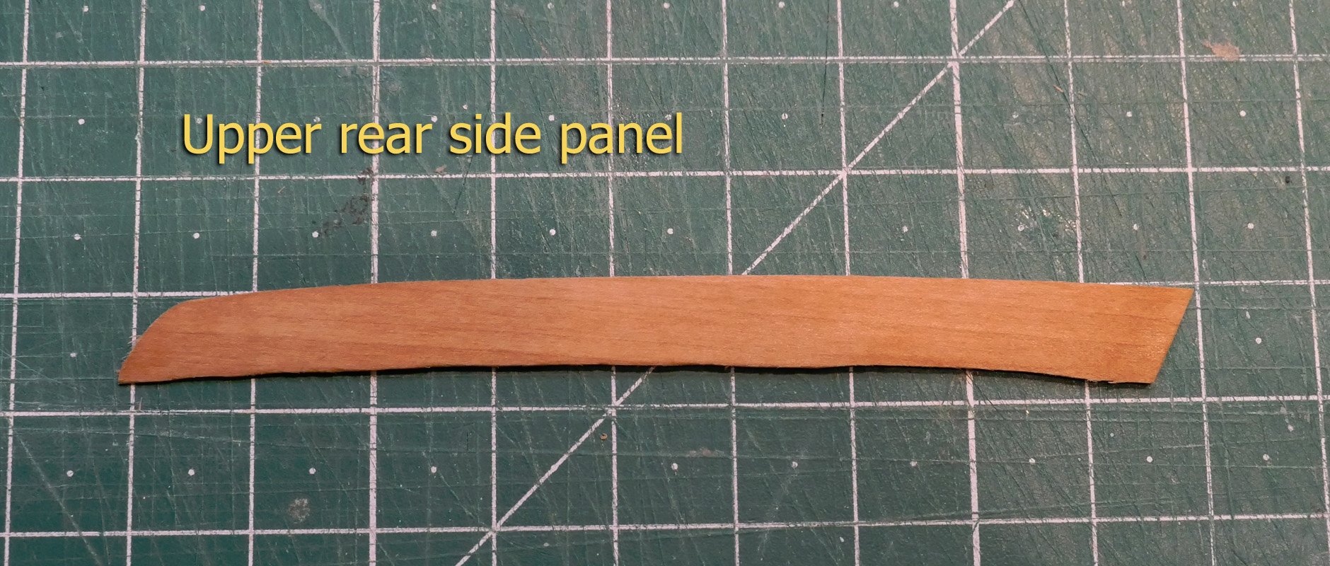
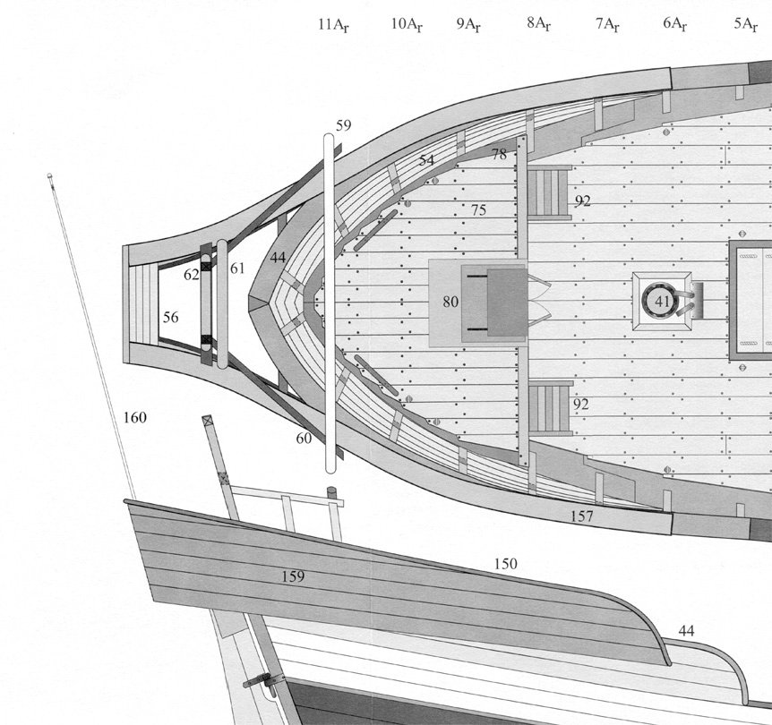
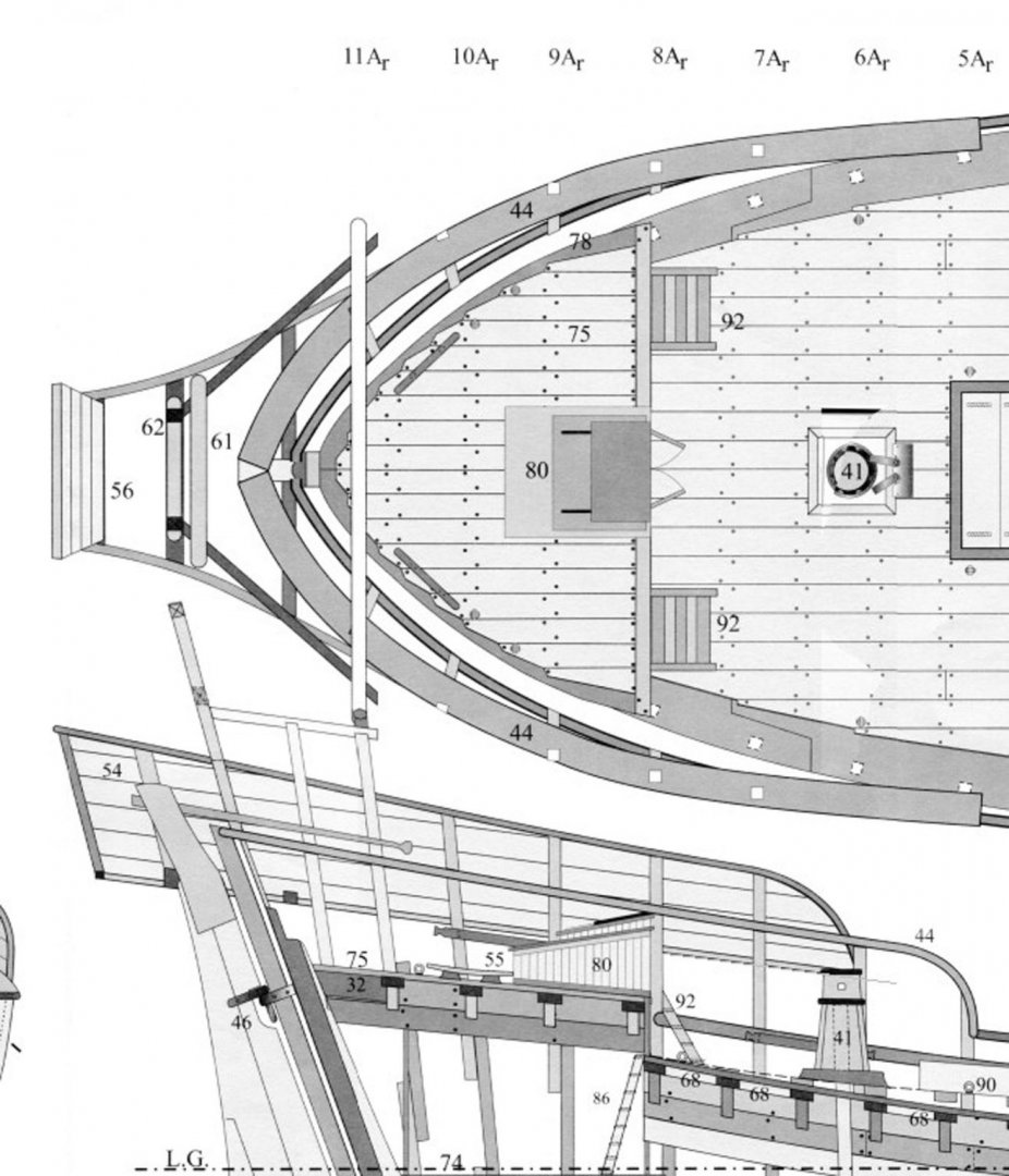
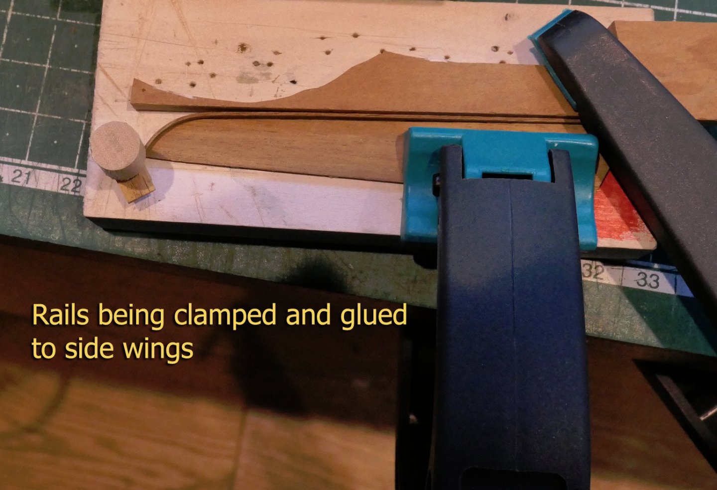
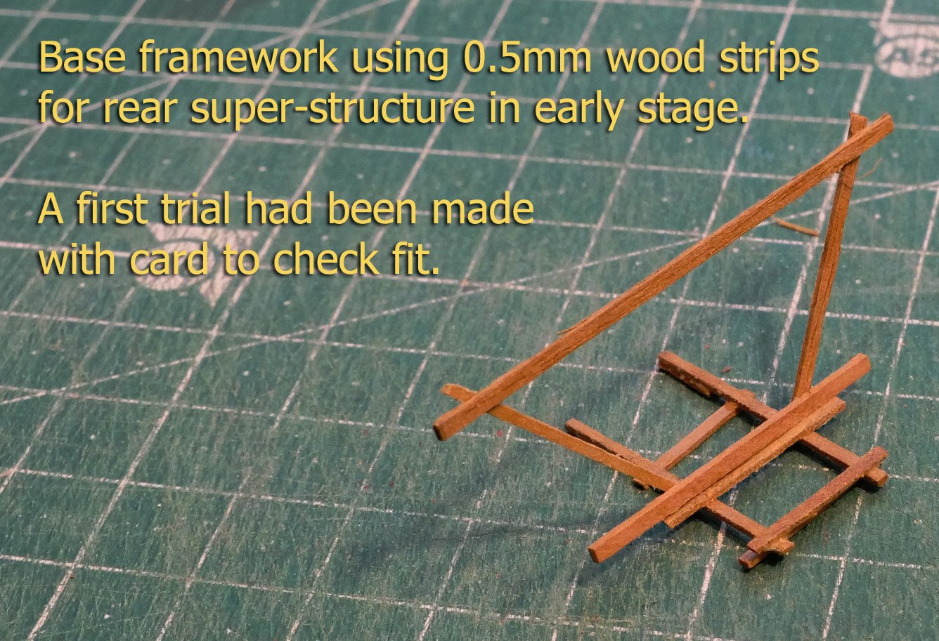
Side wings The build of the side wings posed something of a problem. This was because the build shown by Fissore in his photos differed radically from the plans. The plans showed a complex S-curvature to the wings, whilst the photos of Fissore’s build showed them as straight panels. The side panels as shown on the plans: You'll note that in the plans forward four of the side panel strengthening timbers seem to come straight from the frames below. This would clearly be impossible, and, as you will have seen from the photo of Fissore's actual build, they are as they should be. The side panel made by Fissore (the author of the plans) follows. It was clearly easier to cut the wings as flat panels, so as I could not figure a way of shaping the panels with their internal supports and top rail symmetrical on either side, I chose the easy route and made them flat without curvature. Rear superstructure This is supported by the main top rail. I am unclear about its function. One thought would be that it could provide a base for a tarpaulin to protect the helmsman. Another would be that it helps support the sometimes enormous loads that could be carried by the allèges. Again I made a prototype in card strips to check fit and alignment, then made the final with pear wood. Next up, bow timbers. Tony


-
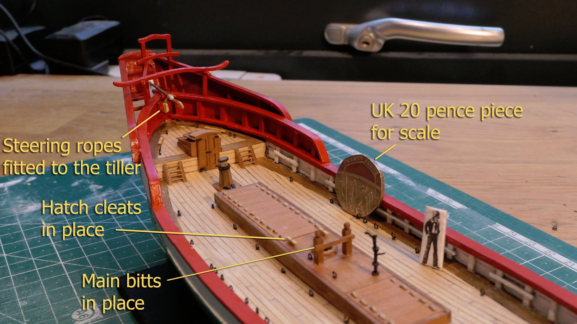
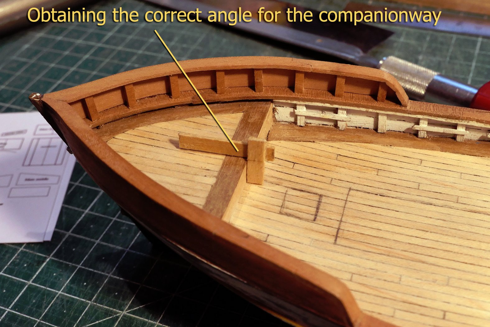
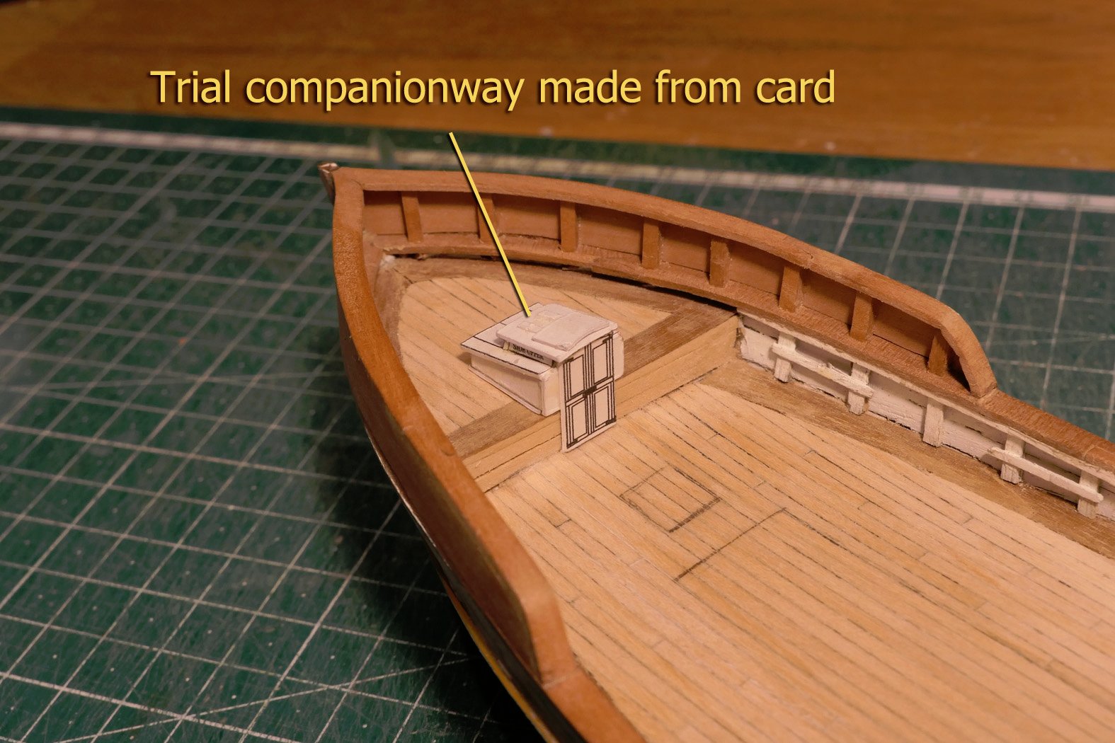
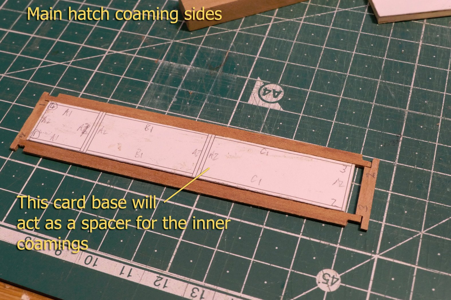
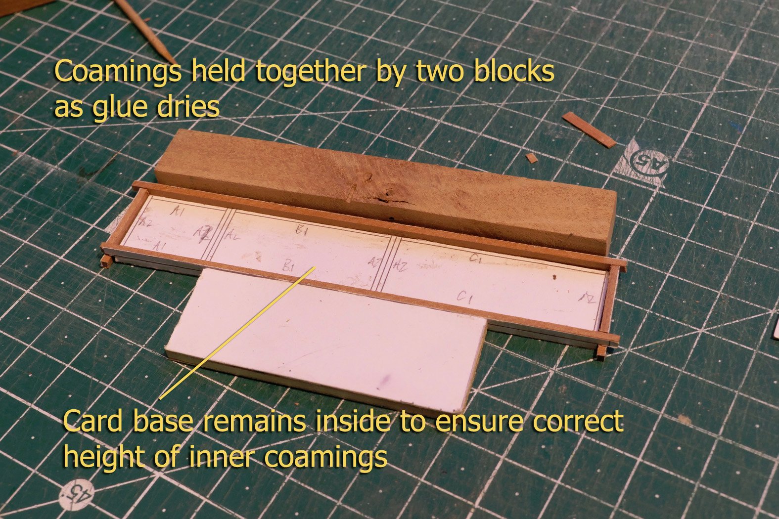
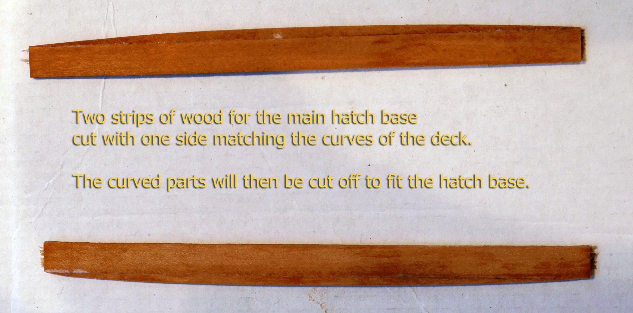
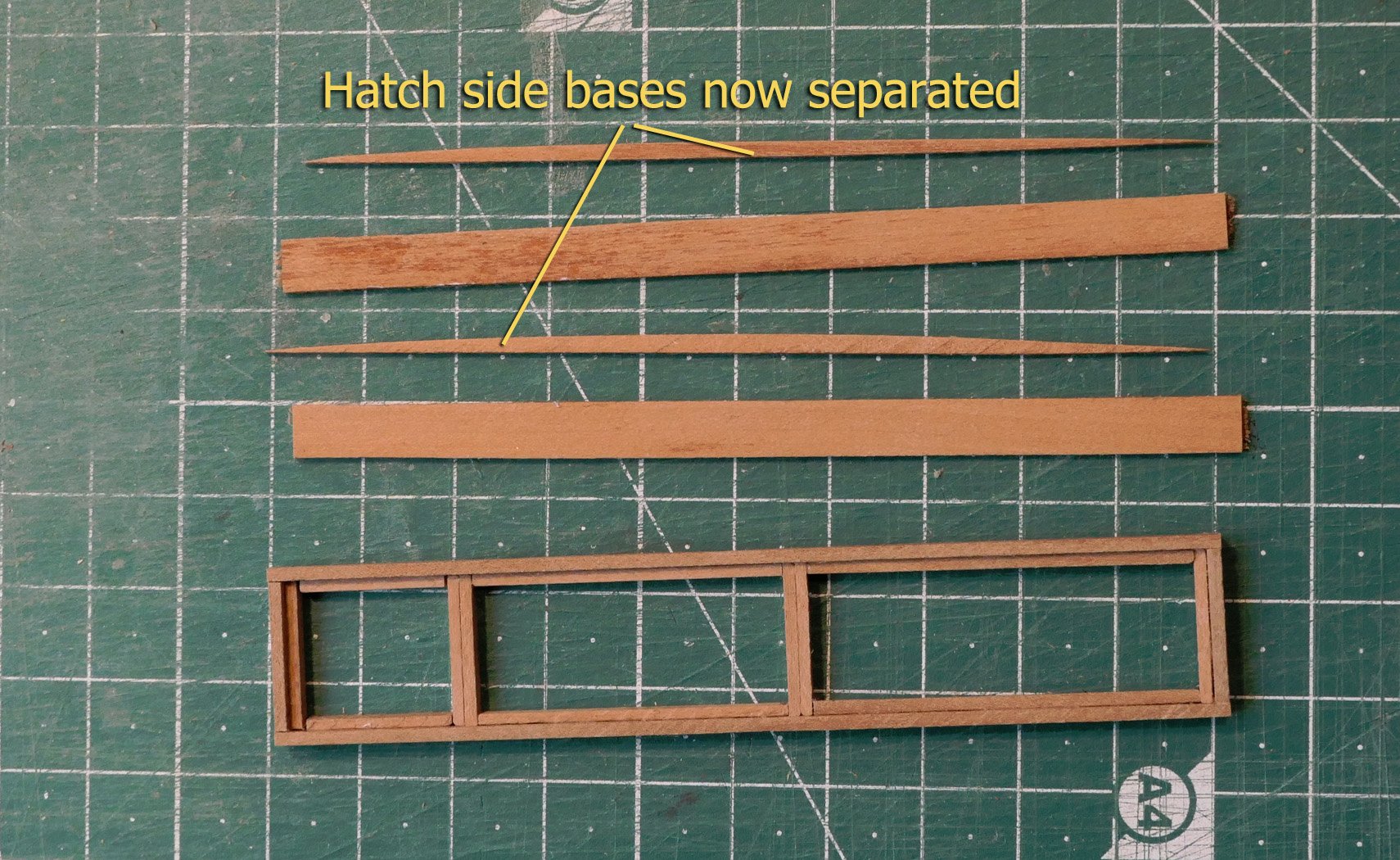
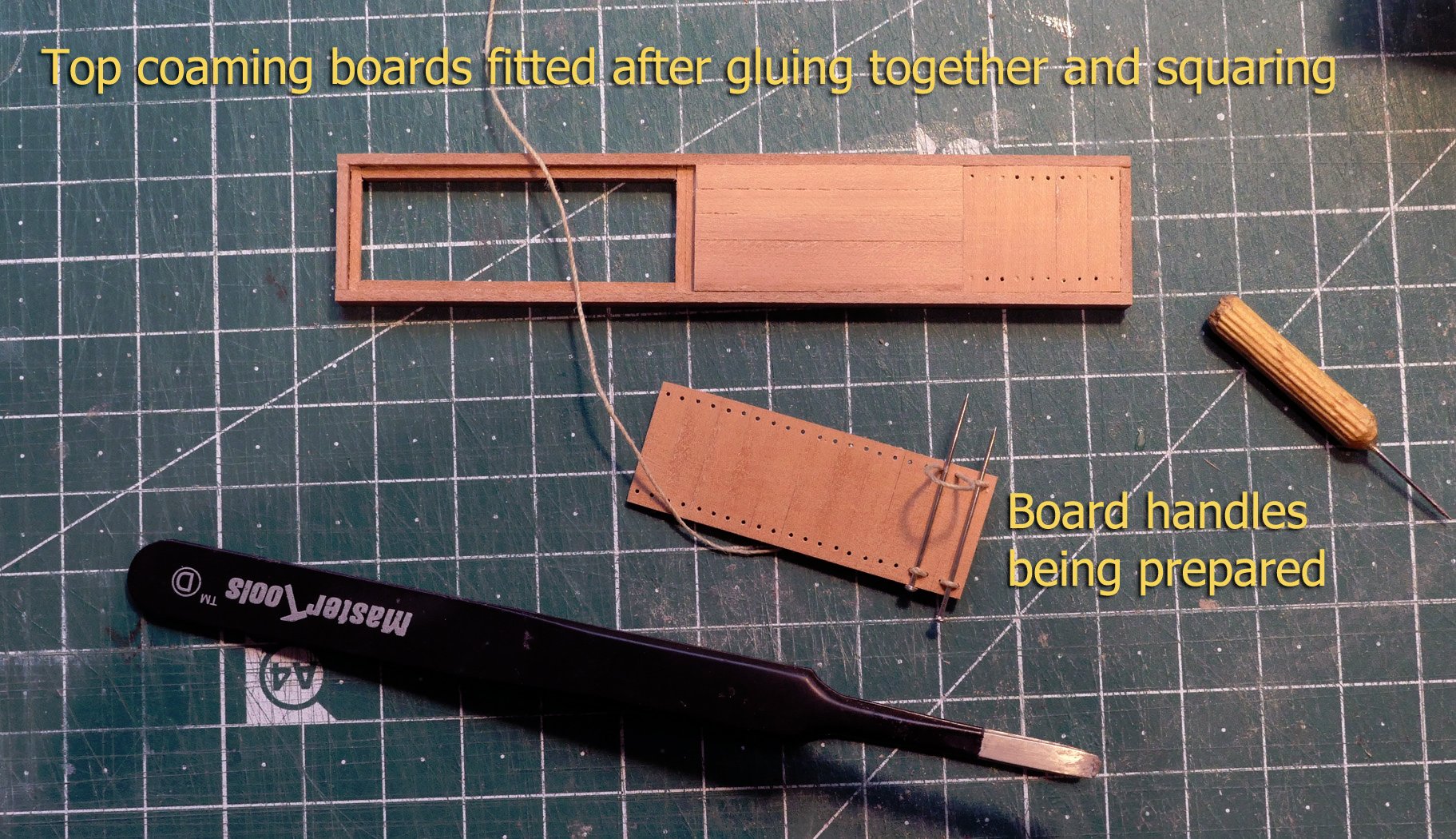
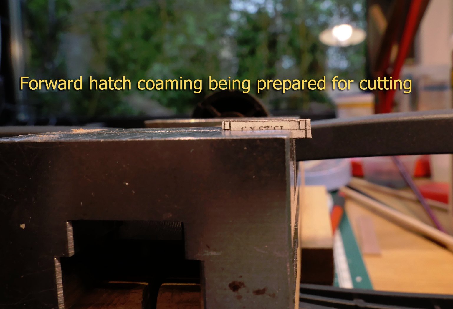
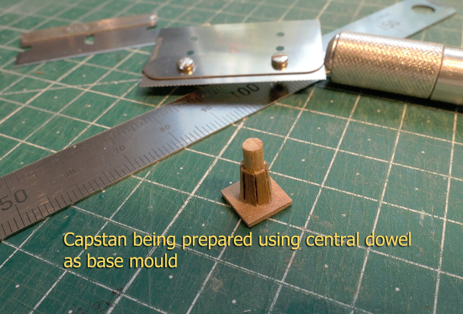
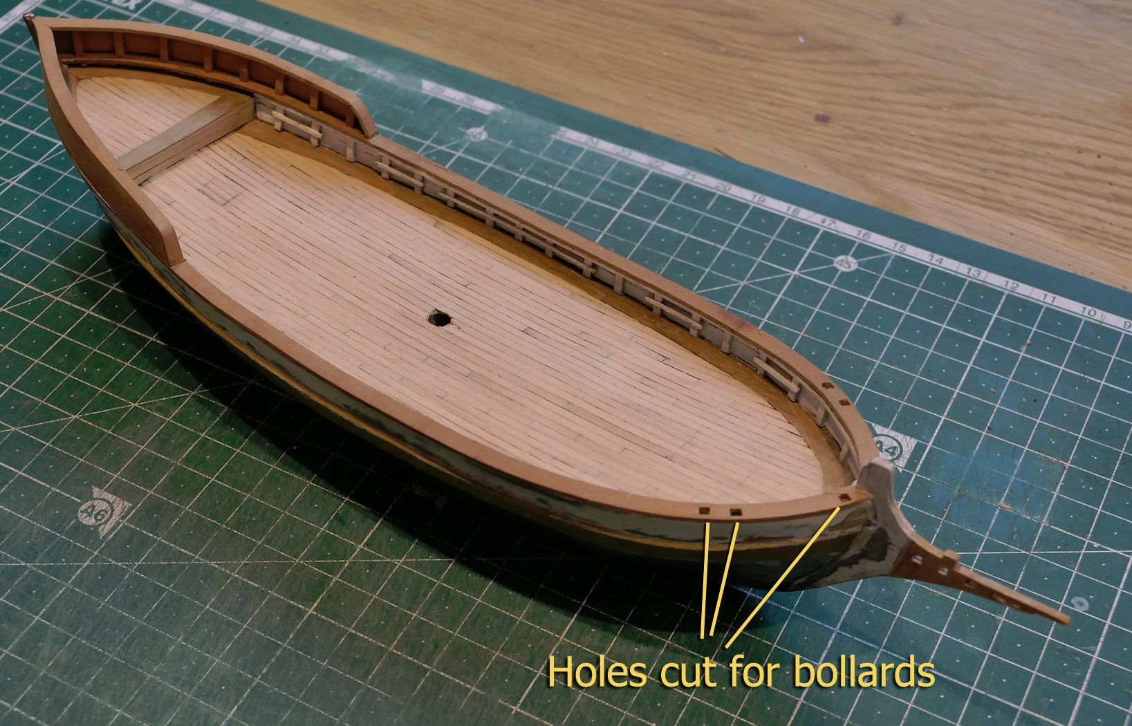
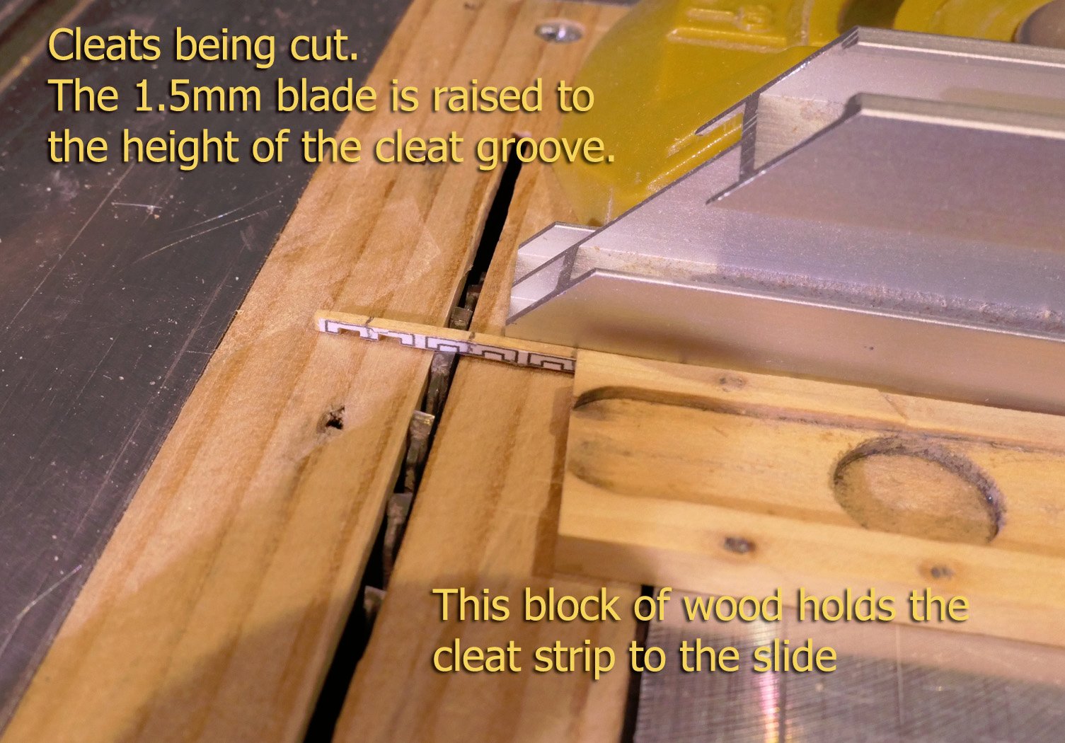
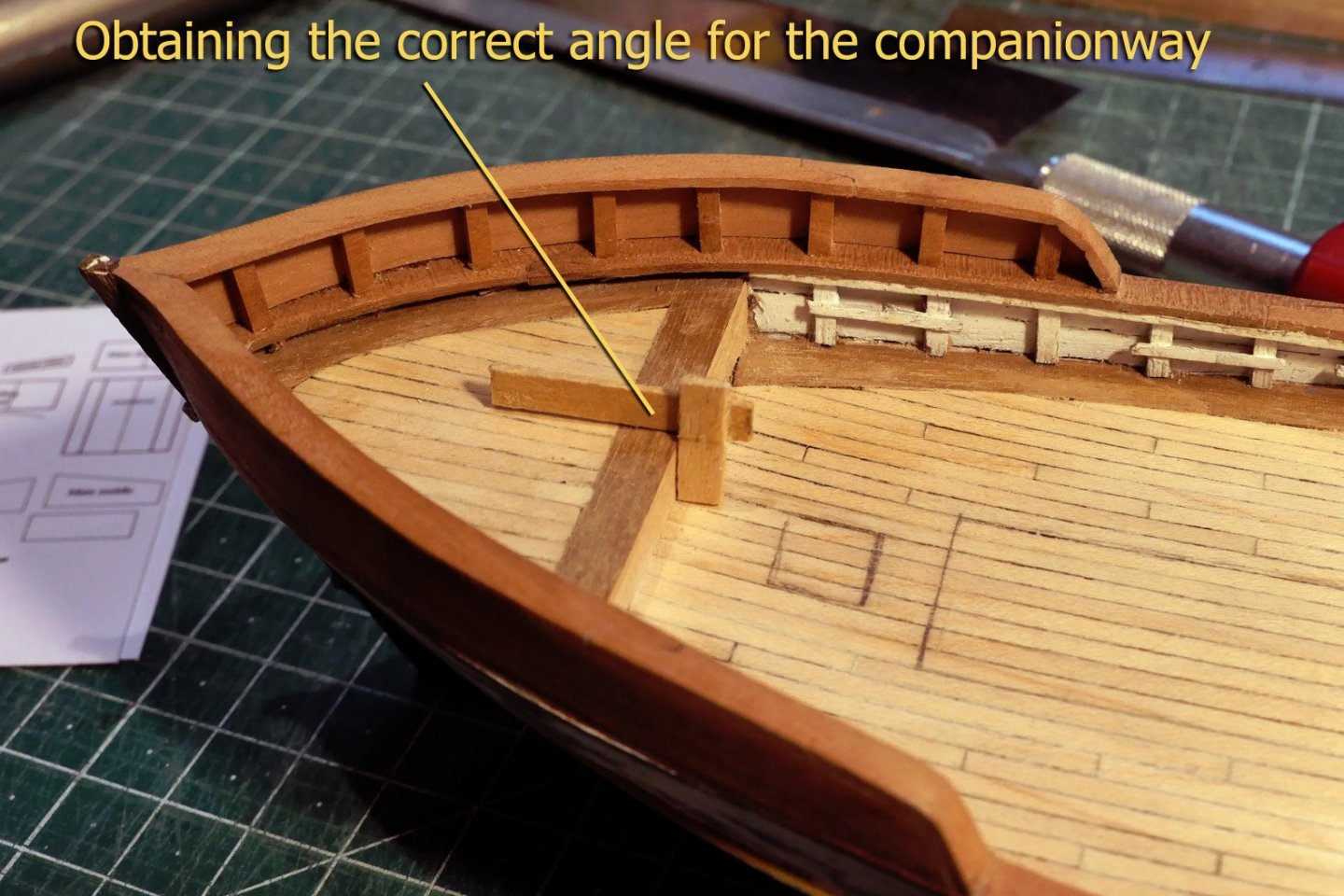
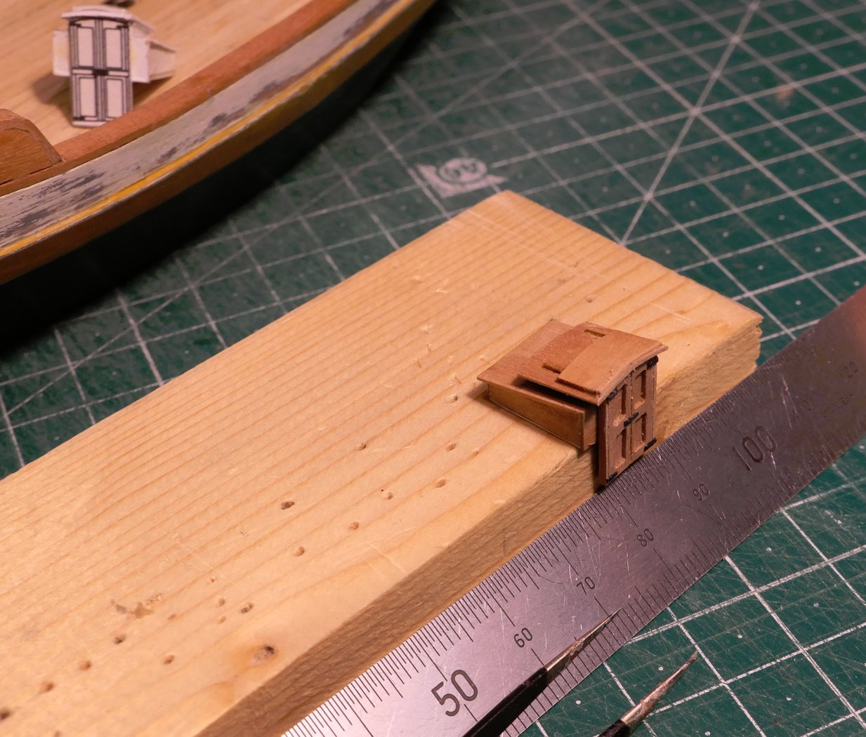
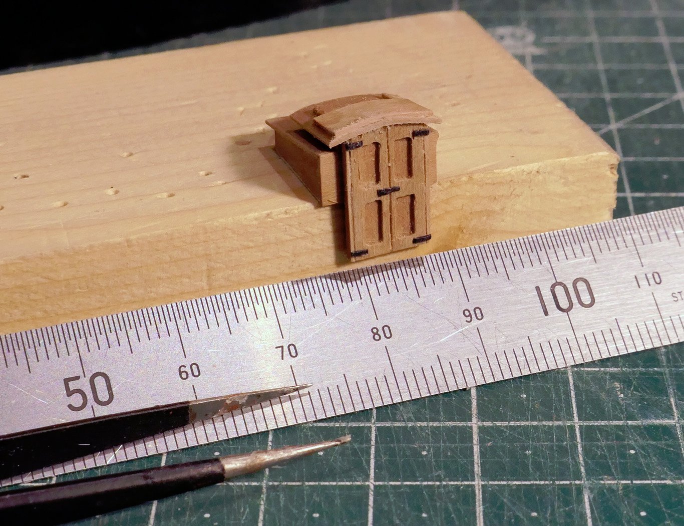
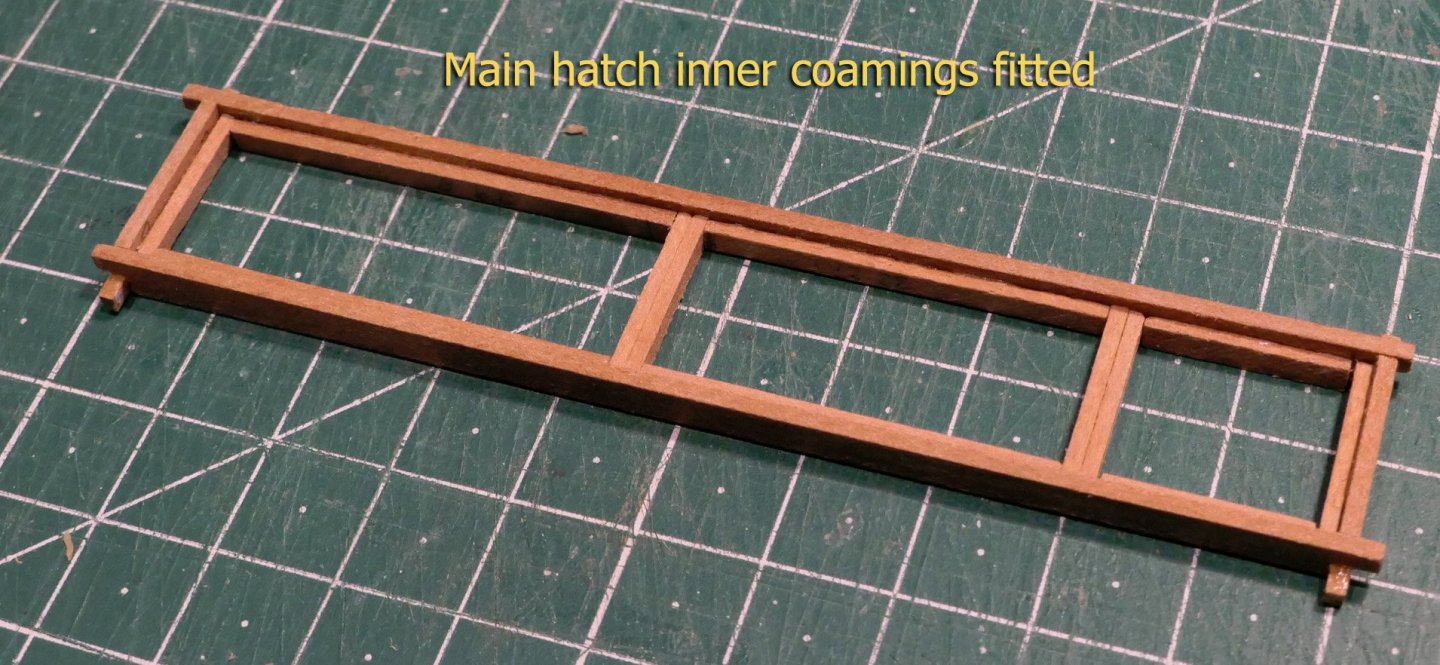
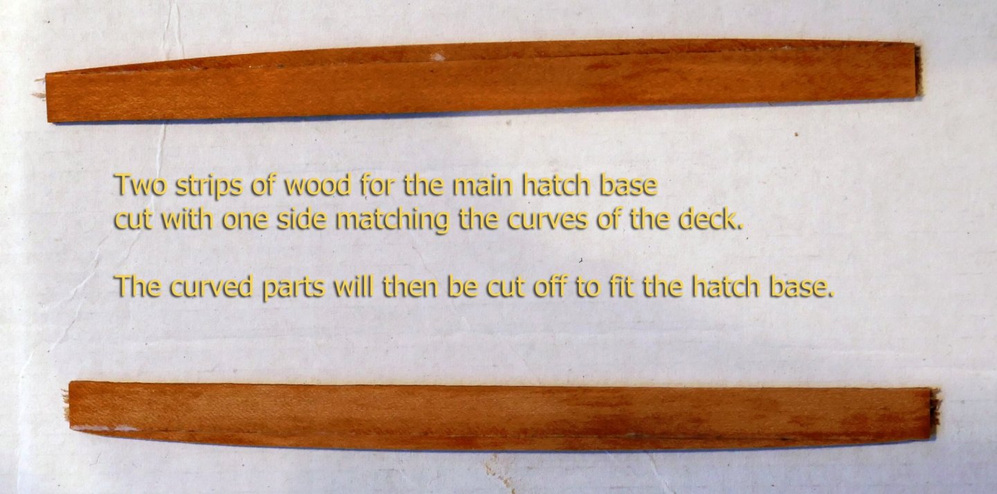
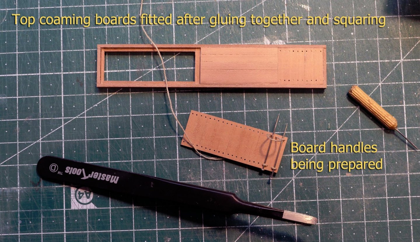
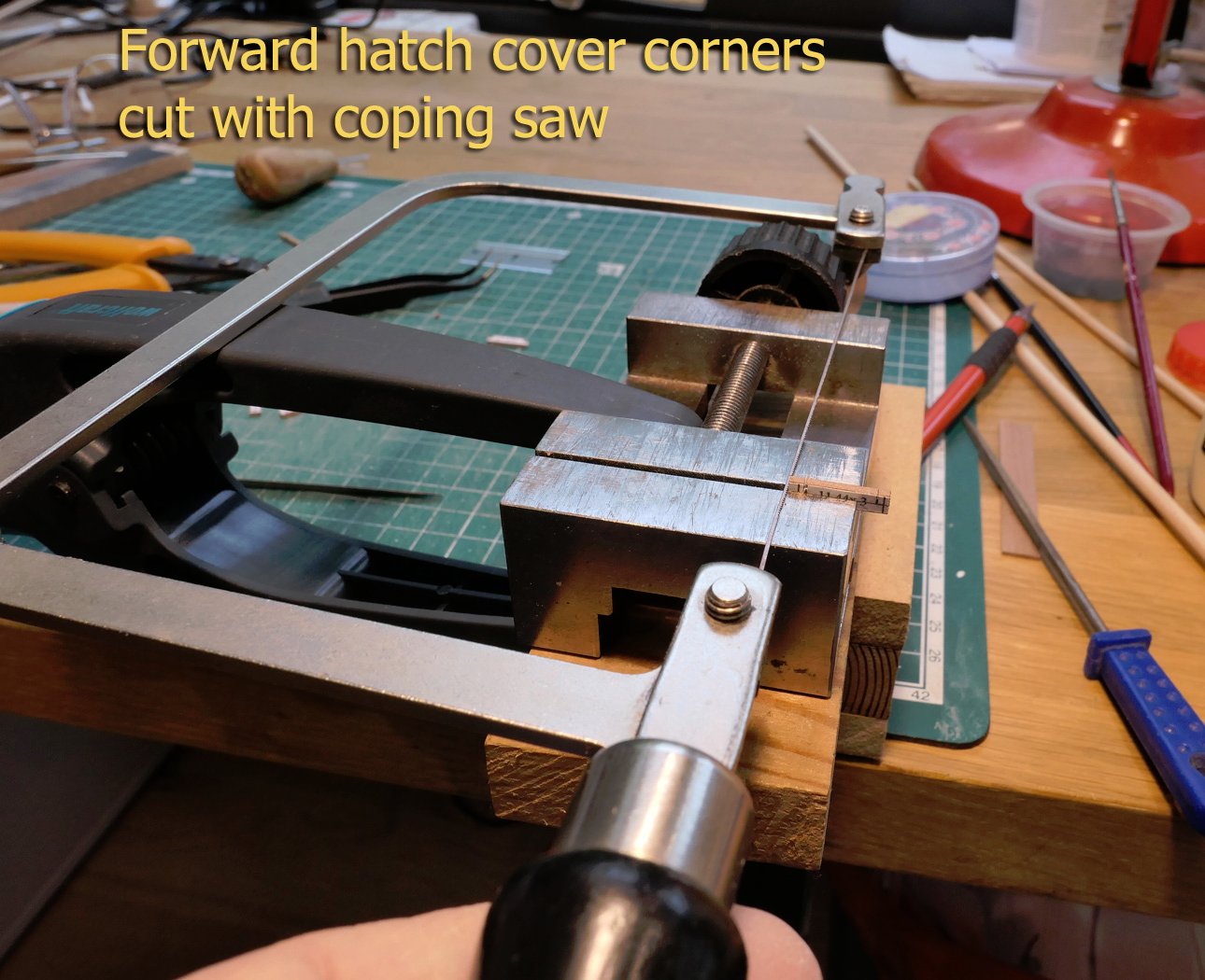
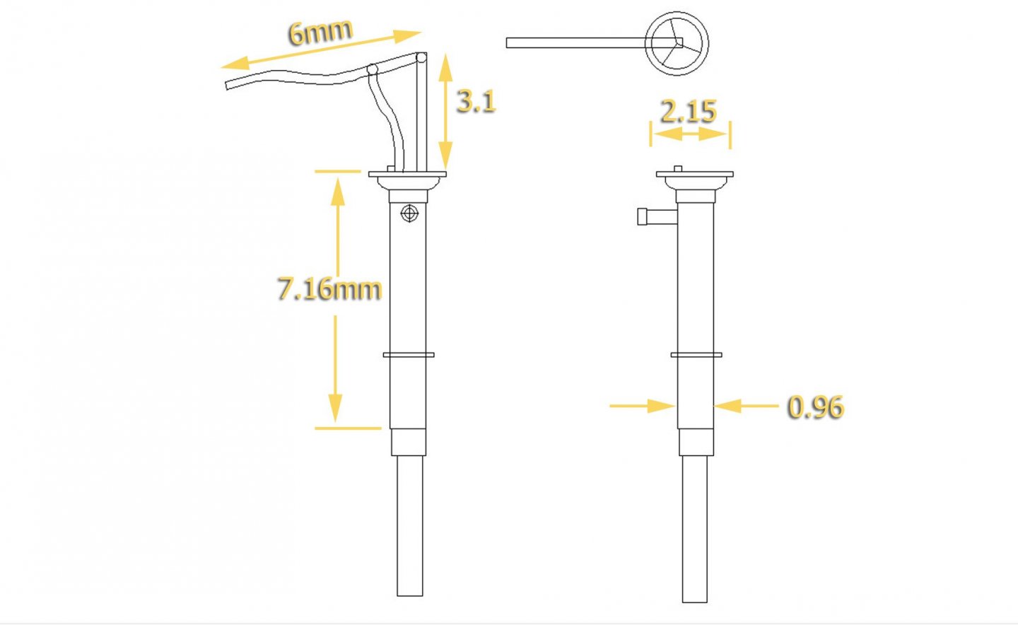
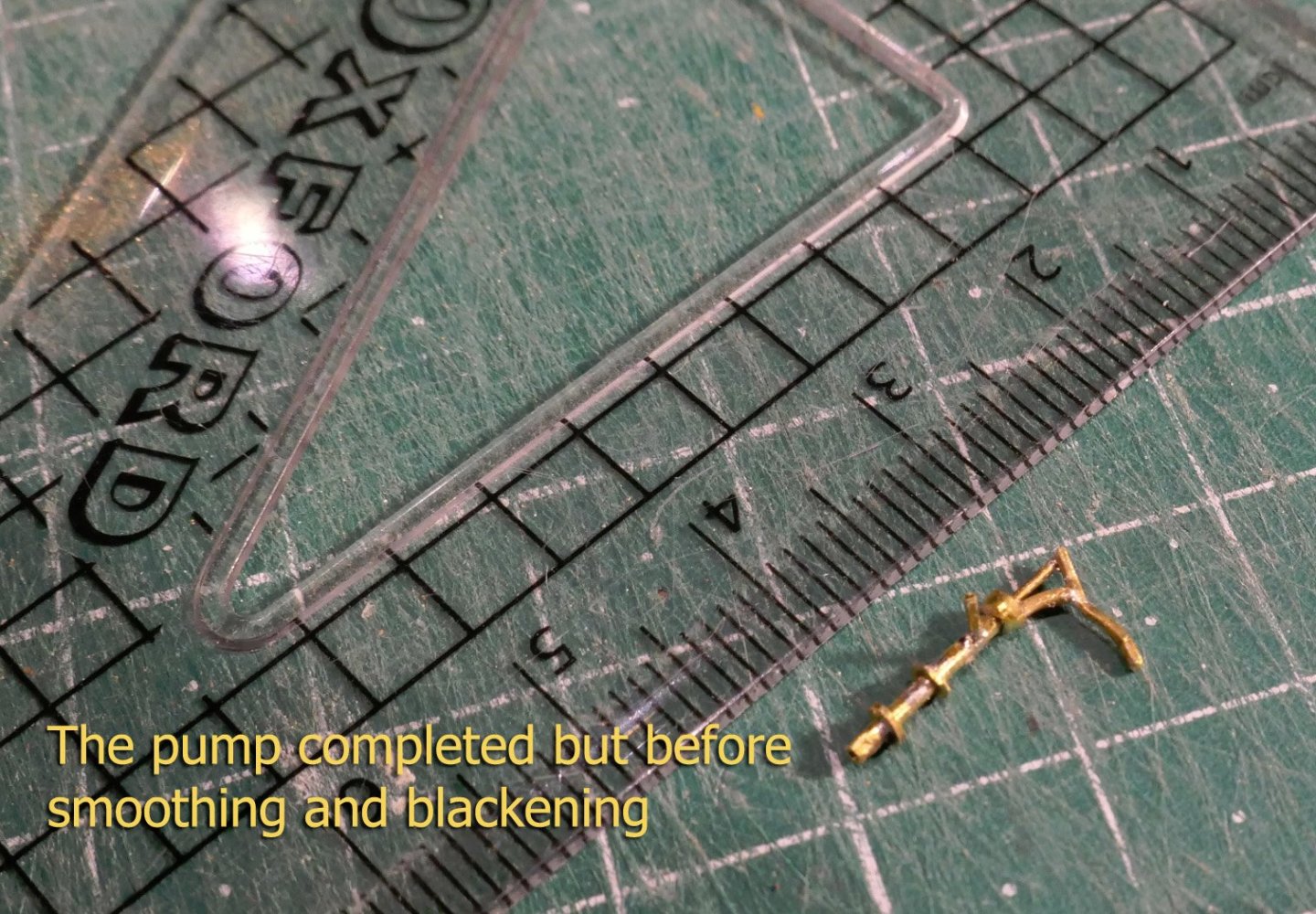
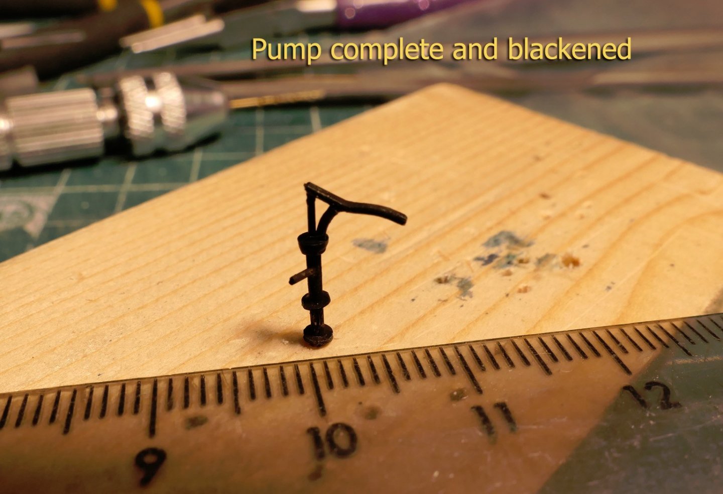
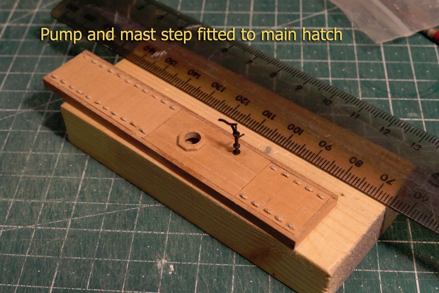
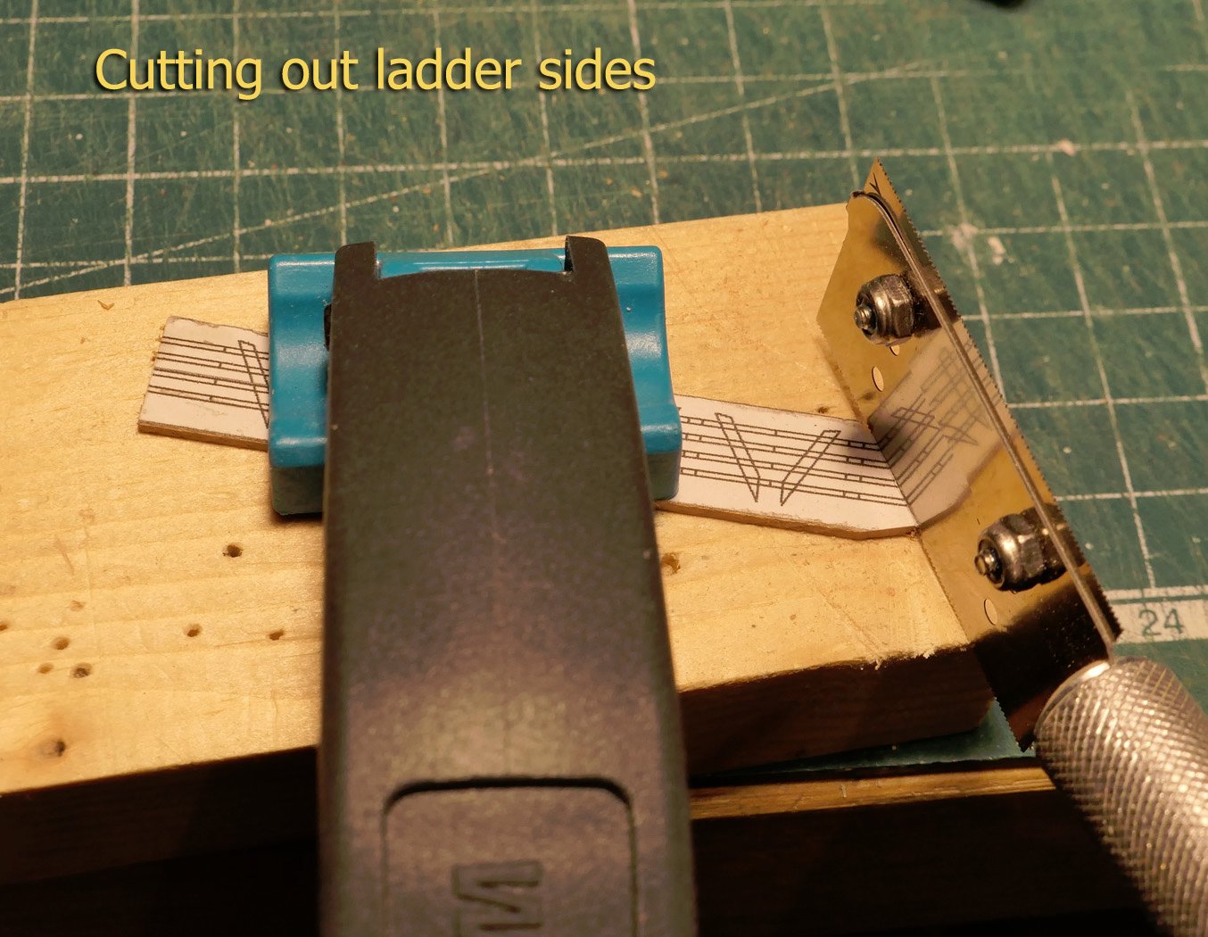
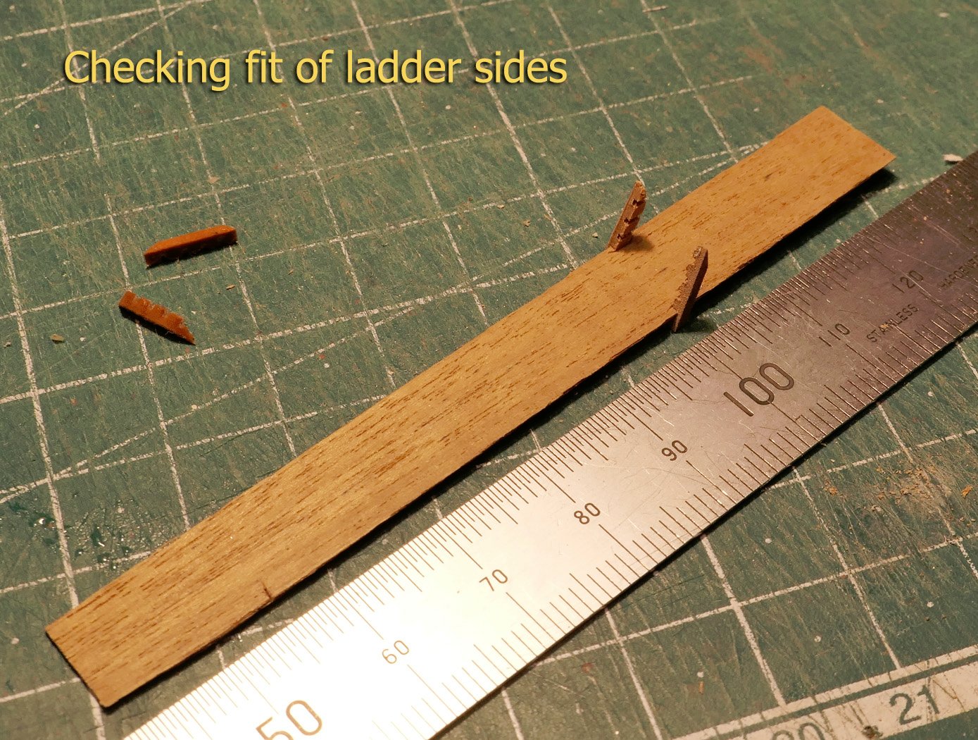
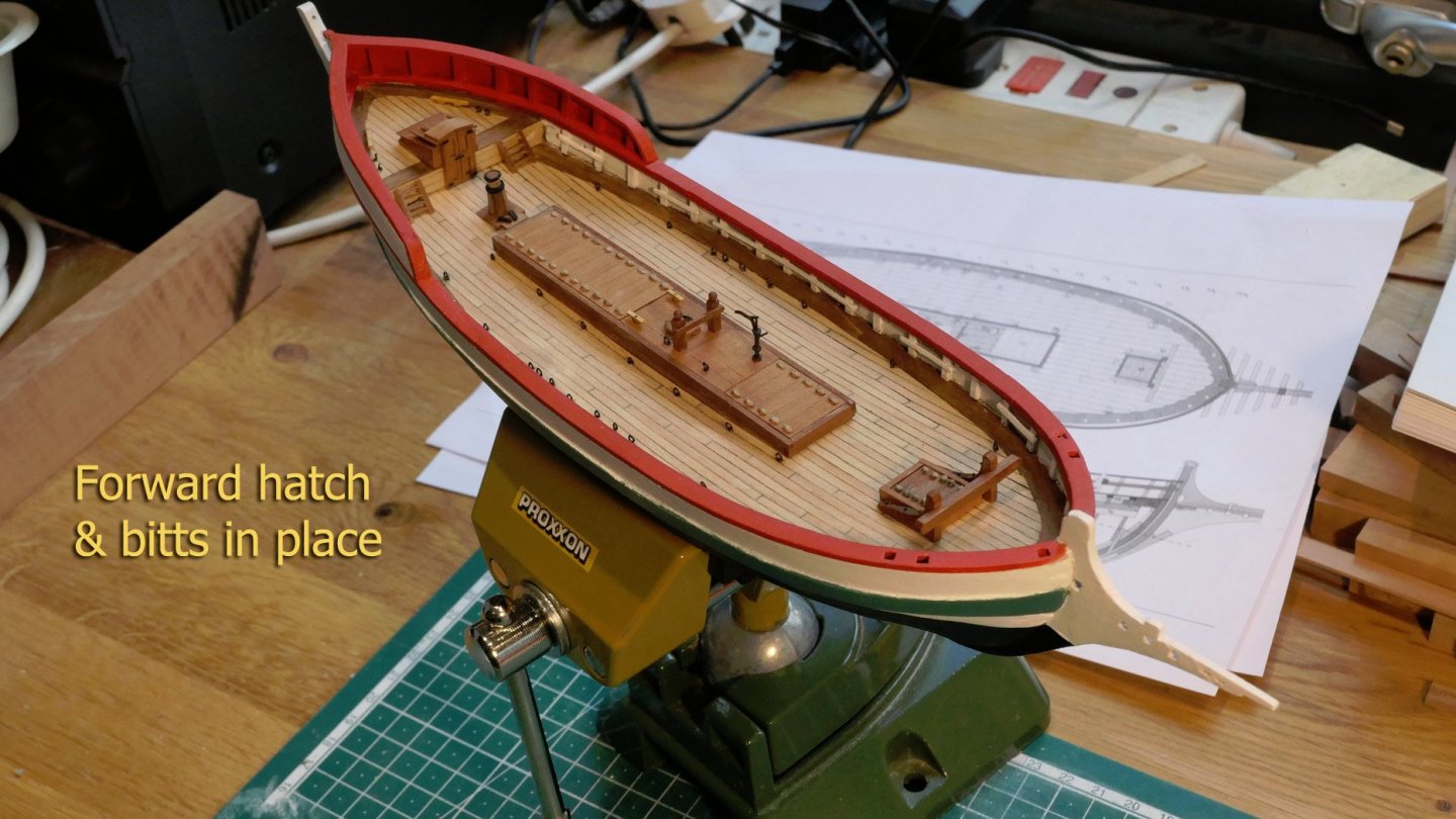
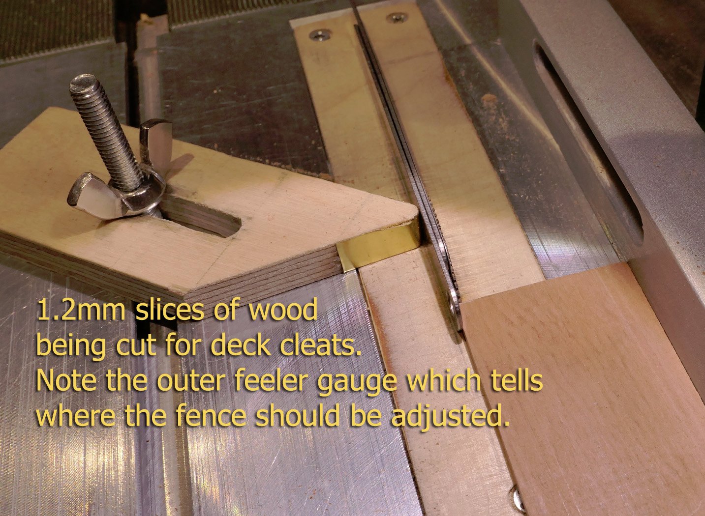
Thanks again for the continuing flow of likes! Deck fittings Companionway This was made after making sure of the dimensions and fitting with a card prototype. First step in doing this was to ensure the angle between the quarterdeck and the deck bulwark. The hinges for the door were made from black card. Because they were so small, they were stiffened with PVA glue. Main hatch The main hatch required a little thought because of the need for an internal framework to support the covering boards. First, a card base was made to match the height of the covering boards. The coaming boards were then fitted upside down along its sides, since obviously the covering boards would be above. Having made the main frame, it had to be prepared so that it would fit the curves of the deck. This was done by making two large strips with one side given the particular curve of the deck. Because, as previously mentioned, the correct curvature of the decks was difficult to match on both sides as a result of the difficulty after placing the plaster filling, the two sides had slightly different curvatures. These strips were then cut exactly along the top line of their curves so as to fit the bottoms of the coaming sides. They were then glued on using spacer bars between them under the coaming framework. The covering boards are a mix of central planking through which the mast and the pump passes, and boards allowing access to the main hatches. These boards are lifted by rope handles, and were made using 0.3mm rope. This was in fact too large for the scale, but I left them, not finding an easy way of making 0.2mm rope. Forward hatch This followed the same pattern of construction as the main hatch. Here I post pictures of the way I cut the lap joints. Instead of a chisel, I used a jeweller’s saw with the piece clamped in a vice along the line of the joint. Capstan The capstan was slightly more complex to build. I elected to make it on a central dowel and covered it with the polygonal sides made from 0.5mm pear wood. Its iron strengthening bands were made from 0.5mm strips of black card. You’ll see the completed capstan later in the log. Pump The pump was really fun to construct as it required several small brass components. The measurements shown are at 1:100 scale. Ladders The ladders were another fun build to think through. I first cut the channels for the steps with the table saw using a 0.6mm blade. You can see that the drawings of the ladder sides were for their outsides facing each other, with the channels inwards for the saw cut. The sides were then cut with a very thin razor saw, the piece being clamped to the sacrificial wood and the table below. These were then slotted on to a 0.5mm thick strip to test the orientation and fit. You’ll see the completed ladders fitted to the deck later. Bollards Basically the process of making these was to take a long 2mm square strip of pear wood and hold the ends at 450 to a sanding wheel, sanding to the middle of the strip, then rotating the strip and sanding that until a pointed pyramidal end was achieved. Then a very small groove was cut with the razor saw at the base of the pyramid. The strip was then cut off at 3mm long to allow for the 2mm clearance above the rail. Deck cleats I again used the table saw to cut the underneath of the cleats which were then cut off and the ends filed to shape. Next up will be side wings, the rear superstructure. Tony


-
I can't quite understand the problem, so maybe I've got it wrong. It seems to me you're talking about the tops that will act as the anchor bollards, as per the illustration on the cover of Sorolla's book on the construction. So, as per the plans, the taller ones face each other on either side of the frames. Does that make sense to you? Tony
-
Wonderful build, with great details about the construction. A great pleasure to watch. Thanks! Tony
-
Proxxon DB-250 lathe extension bed
tkay11 replied to glbarlow's topic in Modeling tools and Workshop Equipment
I bought the extension for mine. Quite low cost from the suppliers at about £20. I agree with Derek, but still find the extension handy when sanding by hand the full length of a mast to a constant angle. The big advantage of keeping the bed short is avoiding the wobble at the centre of long masts if you prefer to cut the mast with the chisels. You could build a steady at the middle, but I found when I tried to do that with card it still marked the mast. Tony -
Great blocks! Well worth the effort! It does take time, and I tend to be a bit impatient with mine. I find the smallest I can make with any semblance at all of a block is 2.5mm long so still have much to improve. I use boxwood rulers as well, and have quite a stock, but also have recently been using Castello, which is very close indeed to boxwood -- though not quite the colour or density. Slicing the marked sides is easy if you have a table saw. I just skim the surface with the thickest blade I have. It just takes very precise movement of the fence. For those with planers or thicknessers it's even easier. Another way is to use a plane with spacers as a thicknesser -- something that's been well-documented on this site, but I've never tried that myself. Tony
-
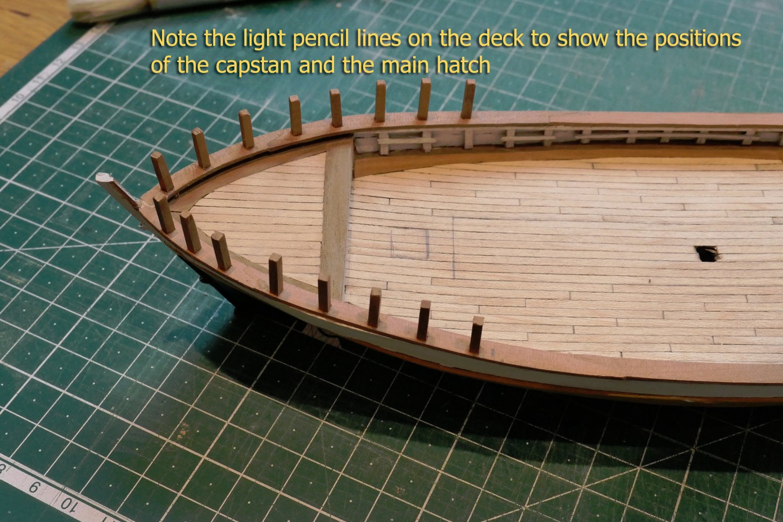
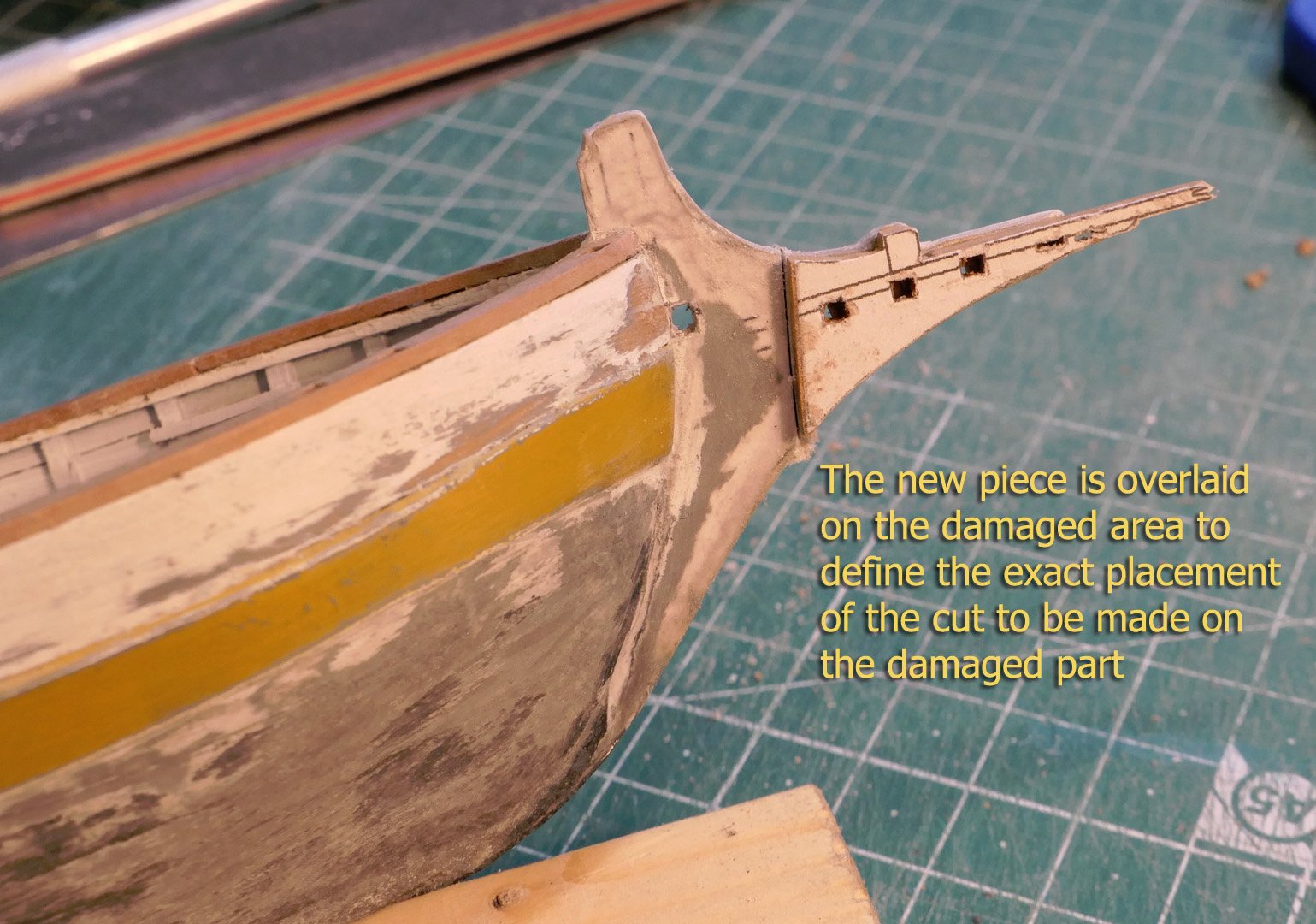
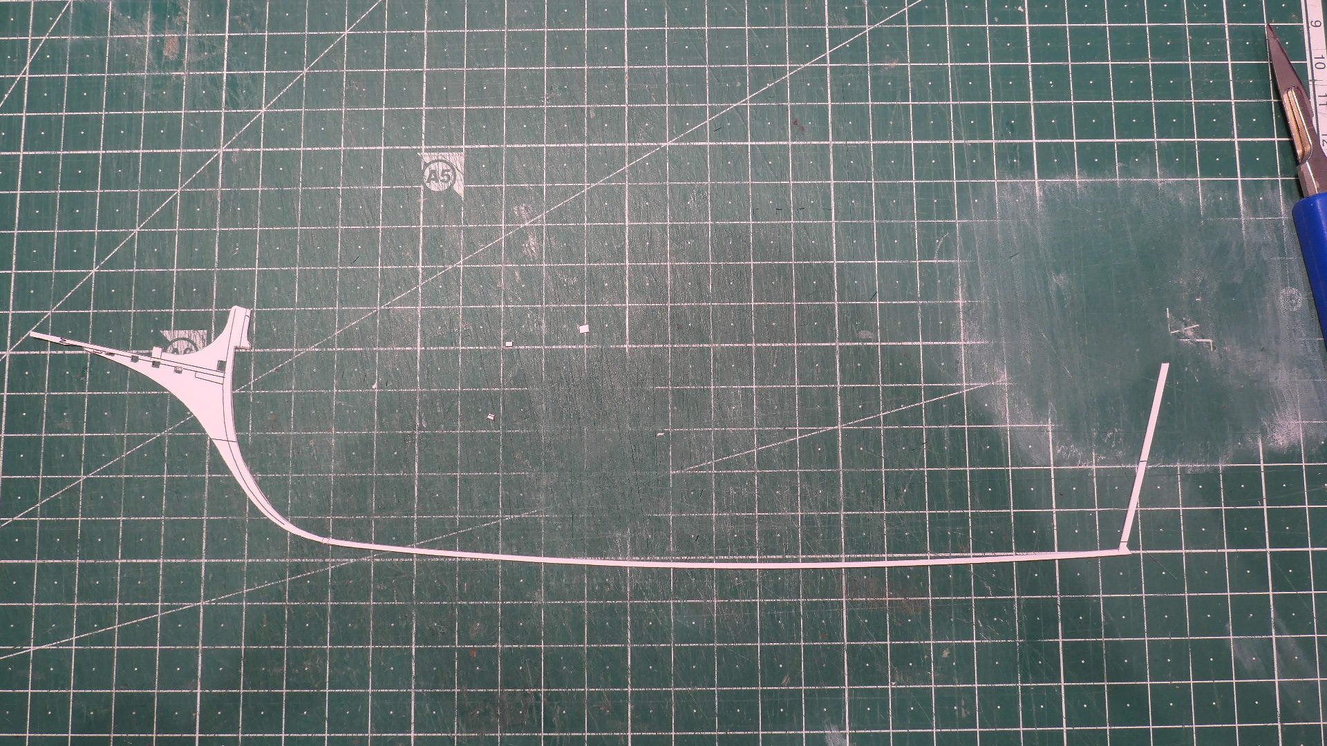
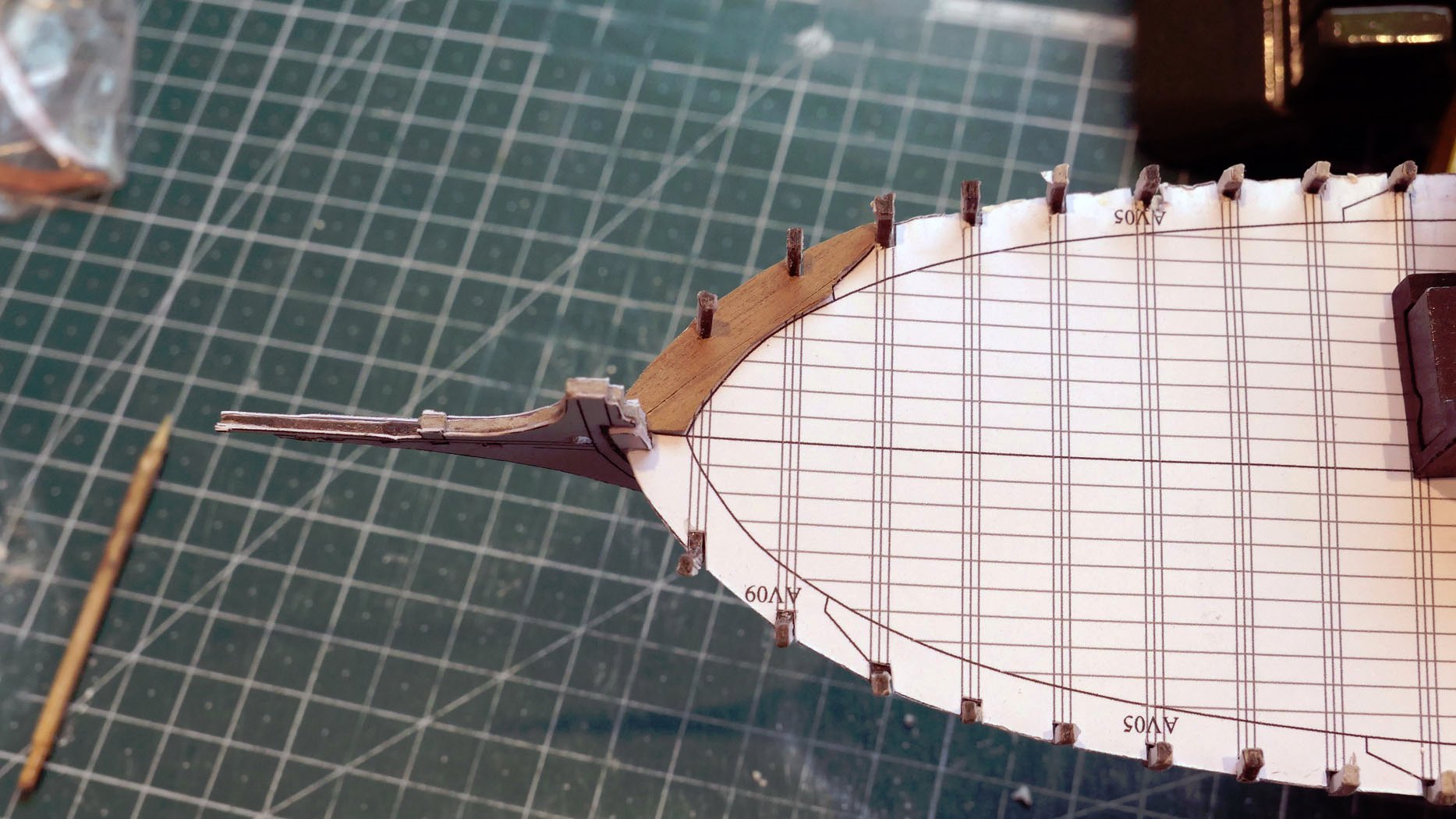
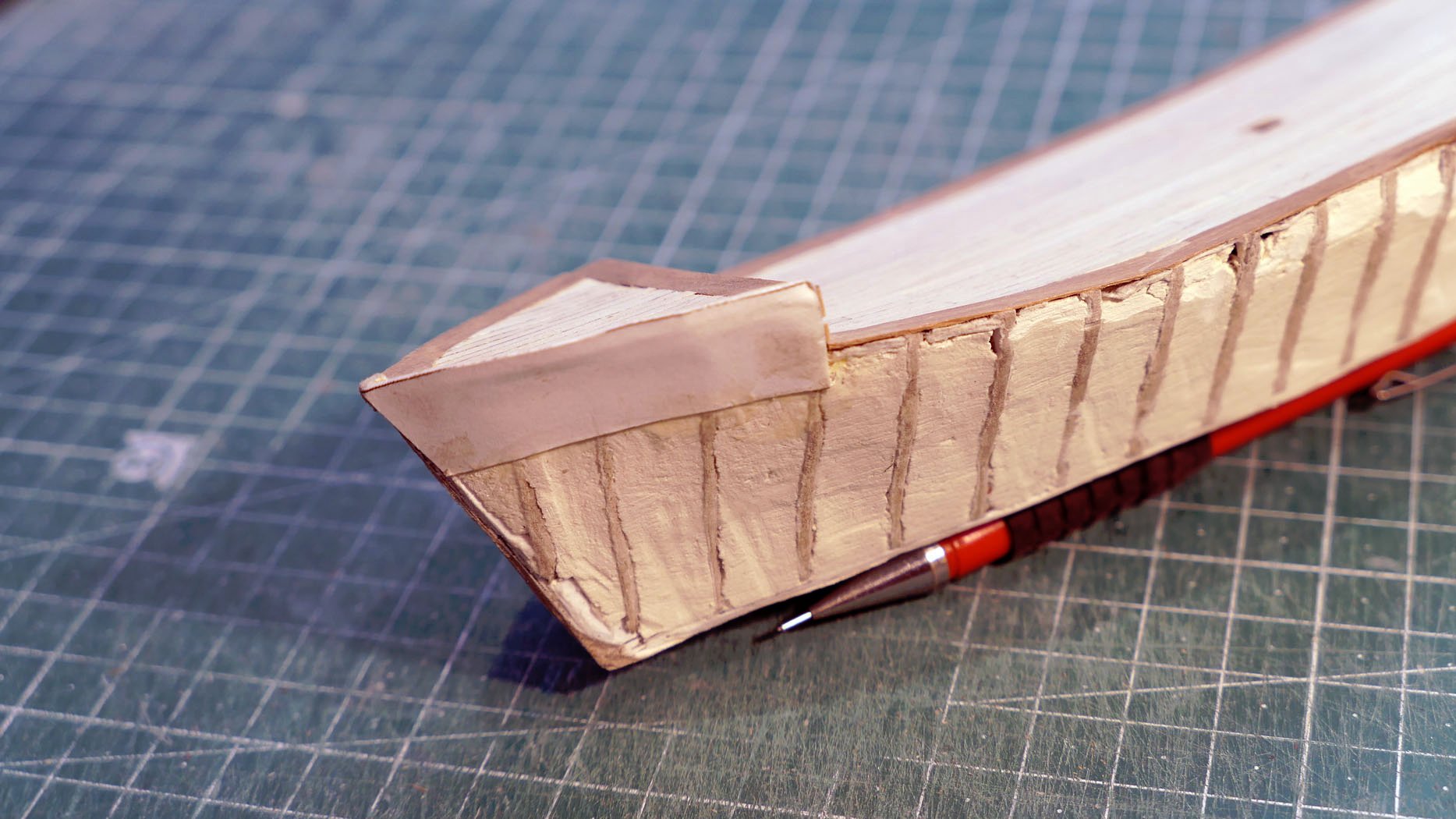
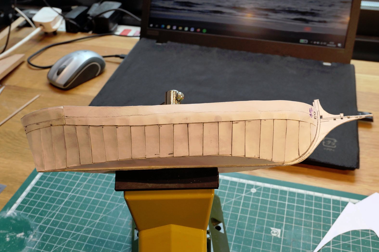
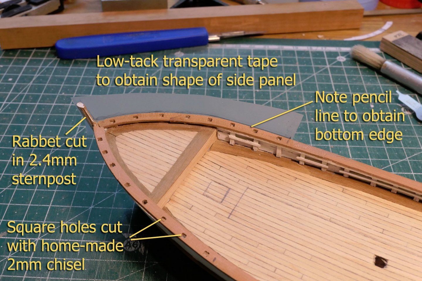
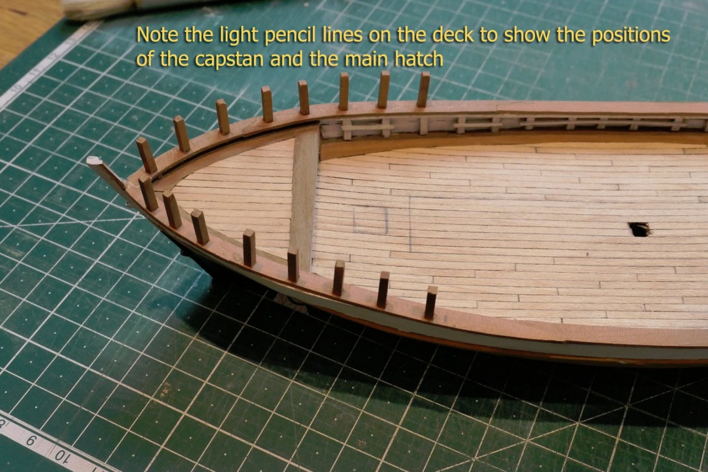
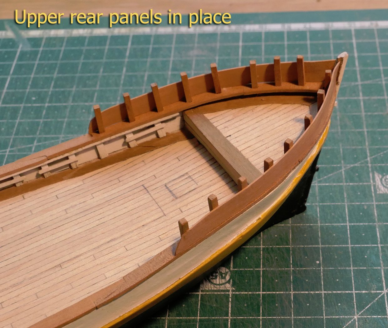
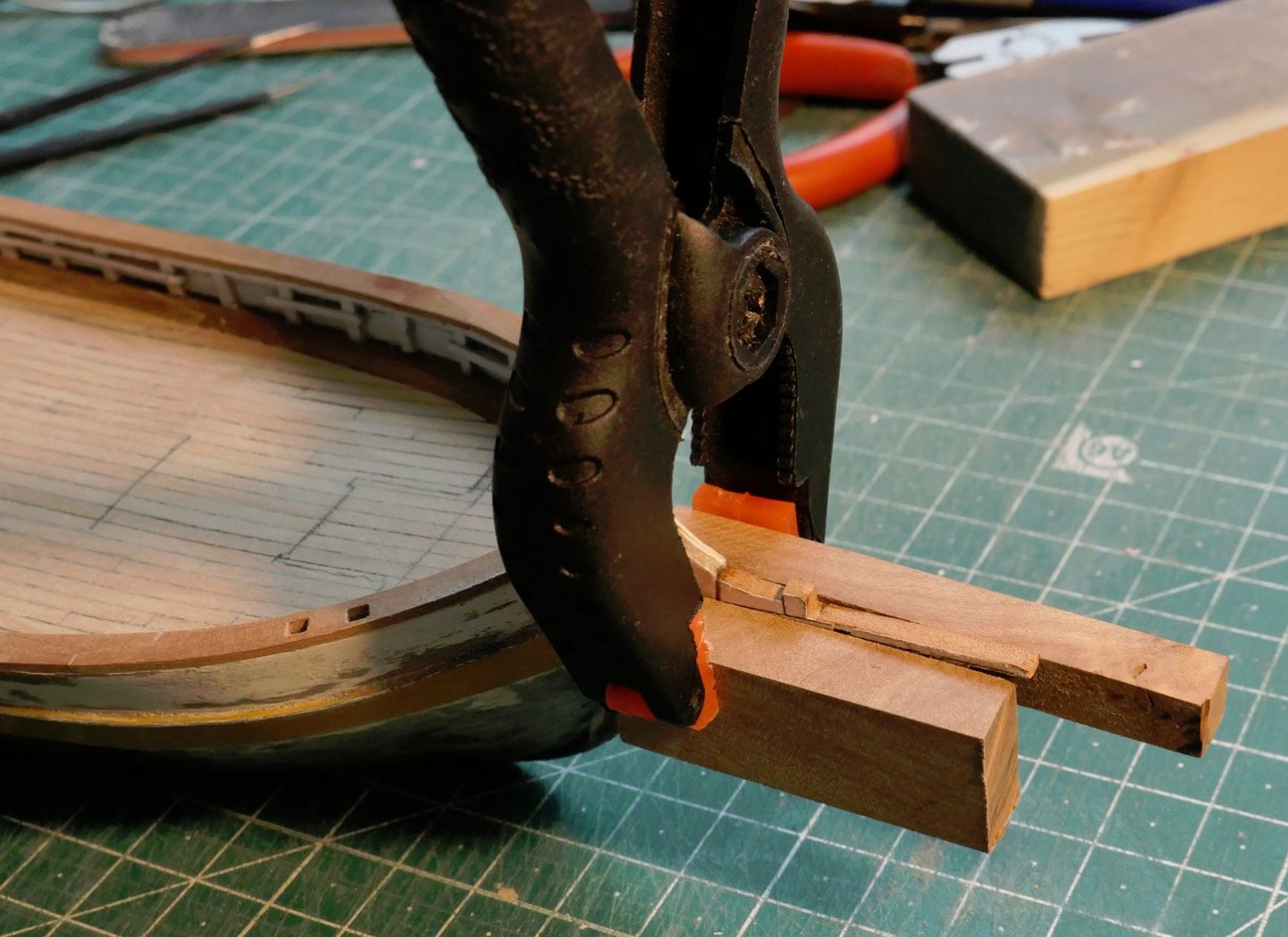
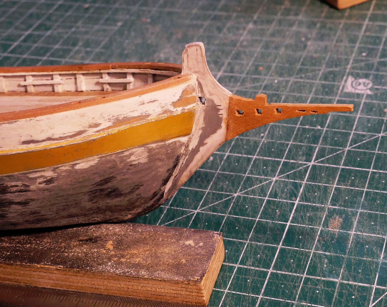
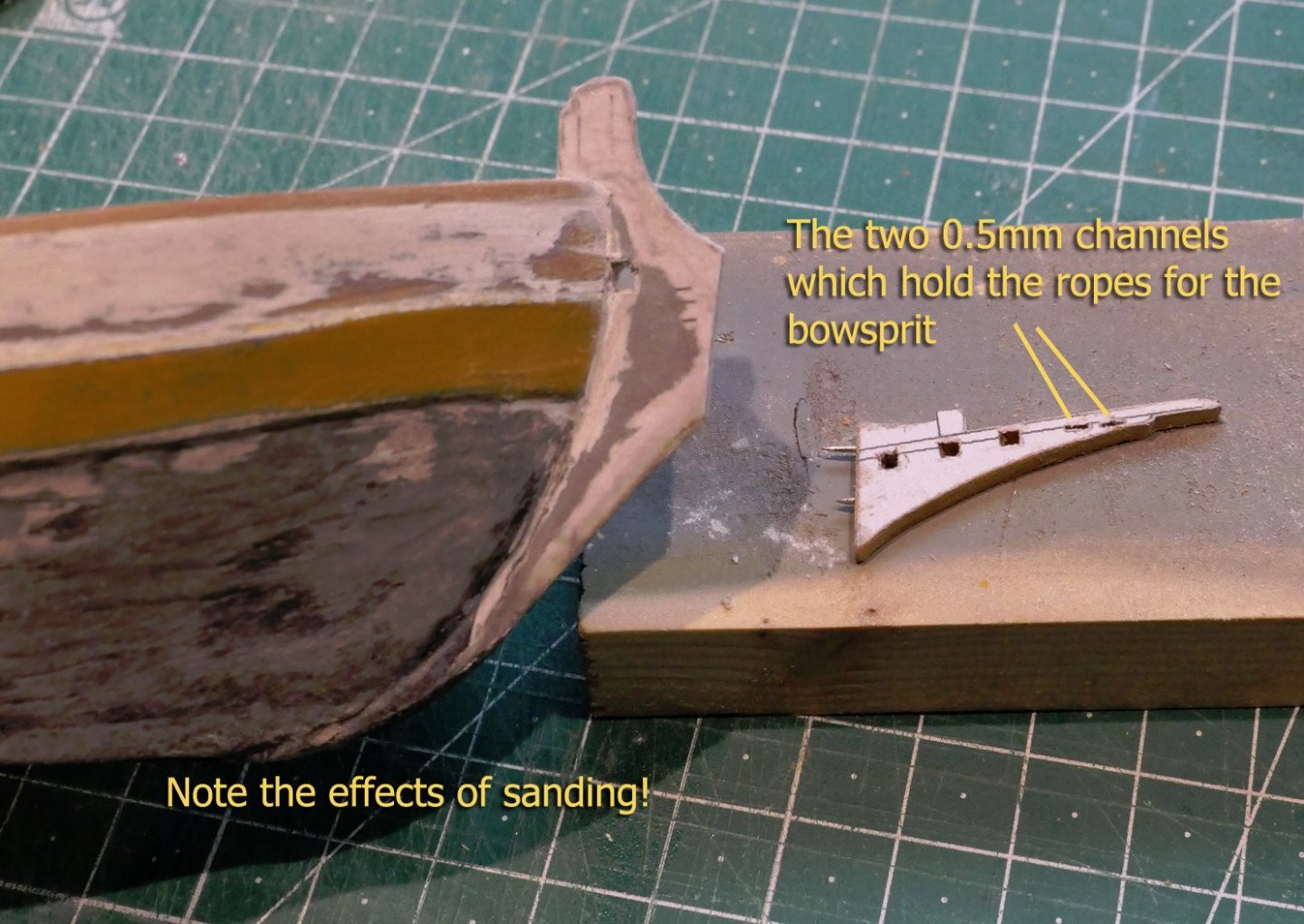
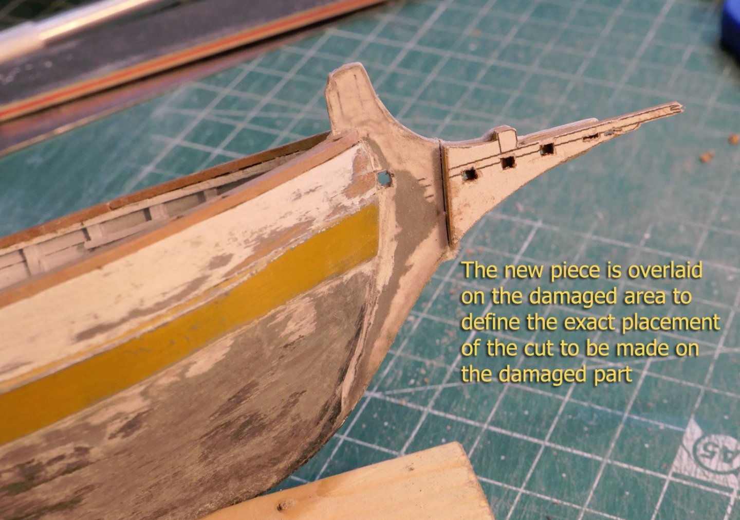
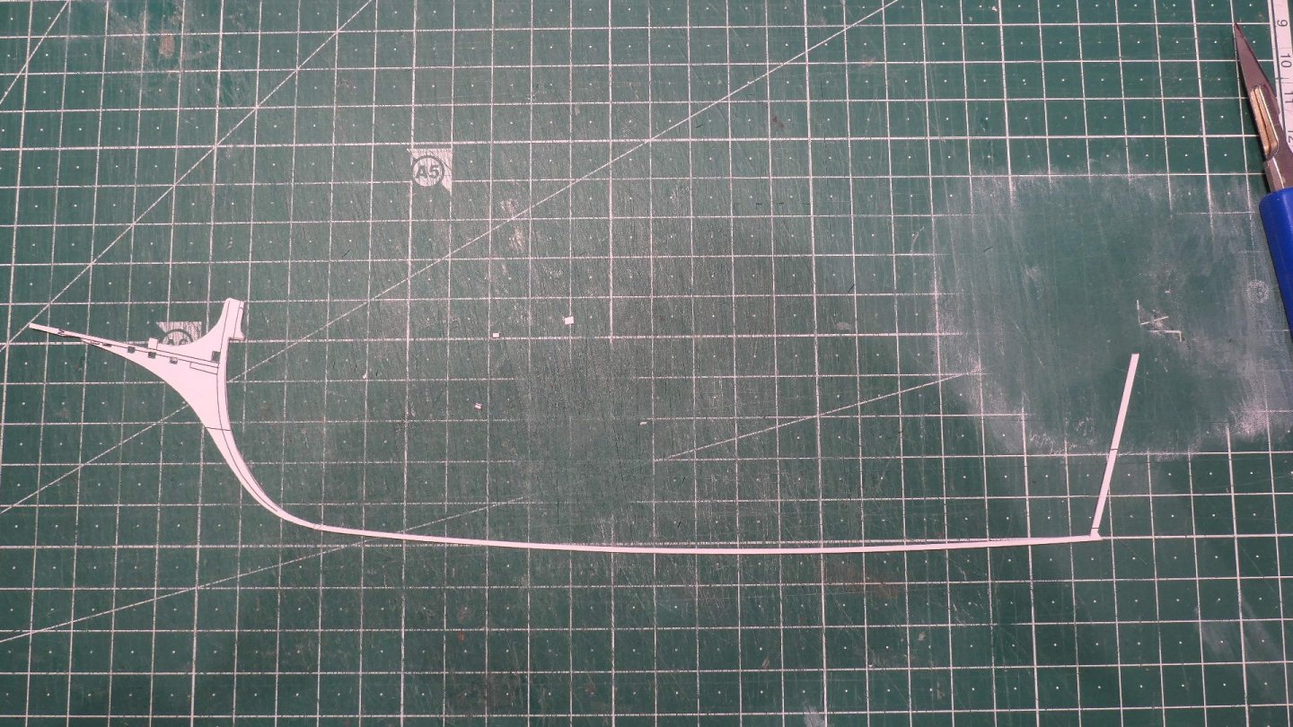
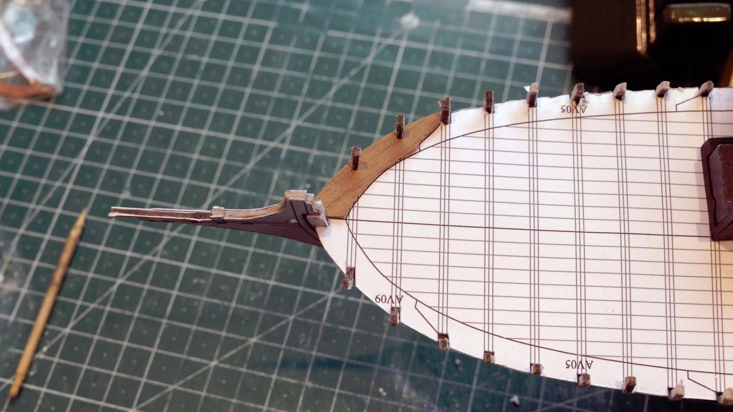
Rear top panels After placing the main rail and the false top timbers, together with the rigging bars along the sides, I made the top rear panels. For these I used low-tack tape to define their shapes (especially the bottom edges which have to fit the curve of the rail). I cut 2mm square holes in the sheer rail to take the top timbers for support of the panels. The pencil marks on the deck in the pictures below are there to show the positions of the capstan and the main hatch. You'll note I've already painted the hull sides. This was because there are two large side panels to be placed over the rear part of the hull. These have a supportive wooden framework which would make it very difficult to paint the hull sides completely after their placement. Problems with the stem and bow The front part of the stem was really delicate. With all the turning around of the body during fitting of the planking and panels, the card structure became seriously deformed, even after putting CA glue on it. This was a potential problem well-noted by Kondzik in his card build. There was nothing for it but to replace it. This became the first of three (AAAARGH!) further reconstructions after similar breaks. I finally overcame the limitations by using a wooden piece to replace the front, leaving the card stem base. You'll note the problems with having first painted the hull. The first clearly was the problems of sanding which I had to do because of the poor finish on the card, which may have been made worse by the water-based acrylics. Part of this problem was the fact that this was also my first attempt at using an airbrush, which took me some time to get used to. This resulted in a slightly patchy finish. The second part of the problem was that of course by cutting off a part and replacing it, the new part would itself need to be painted and the joint filled to match. If I had sanded the base of the stem any further, its surface would have become even rougher. You'll see the effect after the following pictures which show the fitting of the wood replacement after the previous two card replacements. Pretty rough, eh? However, after a lot of time and several thin layers of paint the result was almost acceptable – though you'll only see the results of this painting later in the log. Another thing to note is the very small rectilinear holes at the front of the bow to hold the bowsprit. These are only 0.5mm wide, so required very careful drilling together with the use of a 1mm chisel that I made from a Swann Morton blade. The operation required that I cut a precise line in the stem, and use two strips of dressing pin (0.6mm diameter) to hold the wooden piece to the stem. I used epoxy glue and two strips of wood to clamp the parts together. I'll continue with the completion of the rear sides and the deck fittings in the next posts. Tony

- 41 replies
-
- 10
-
-
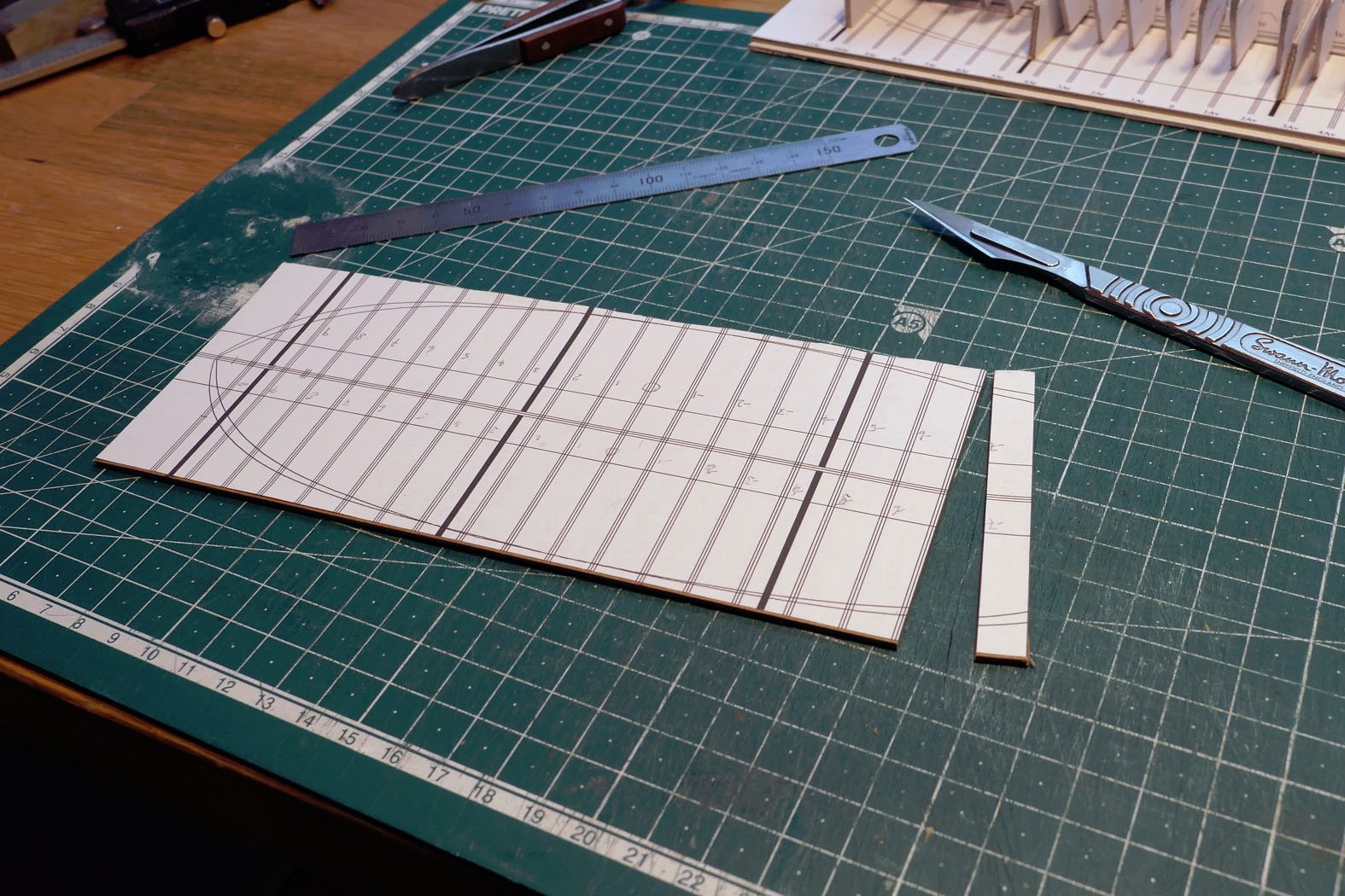
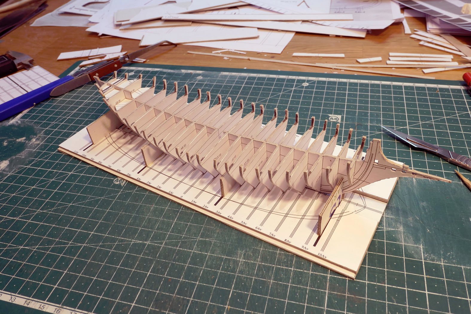
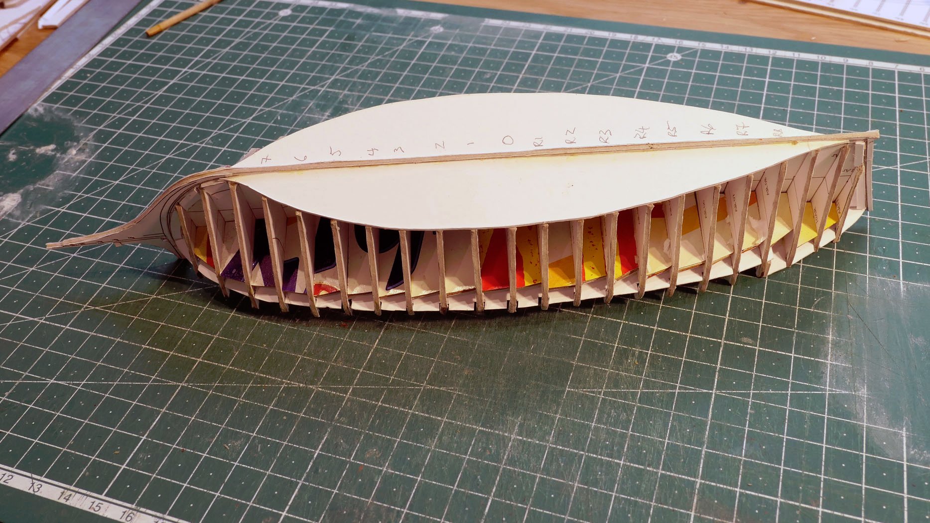
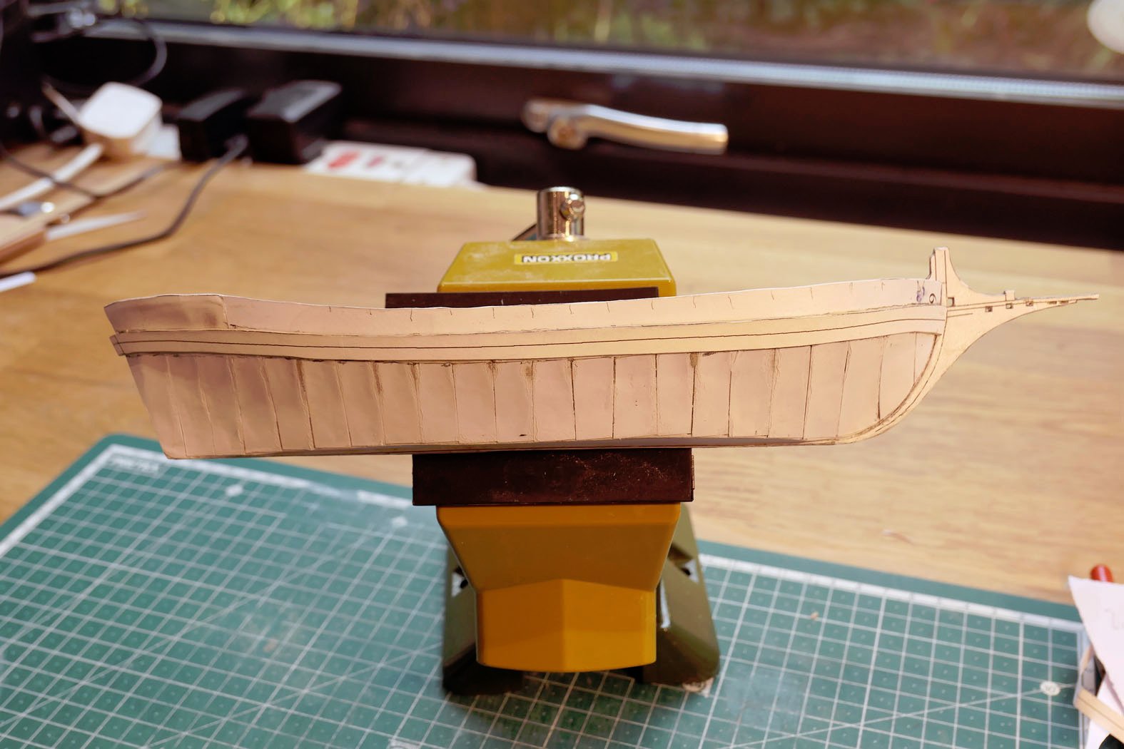
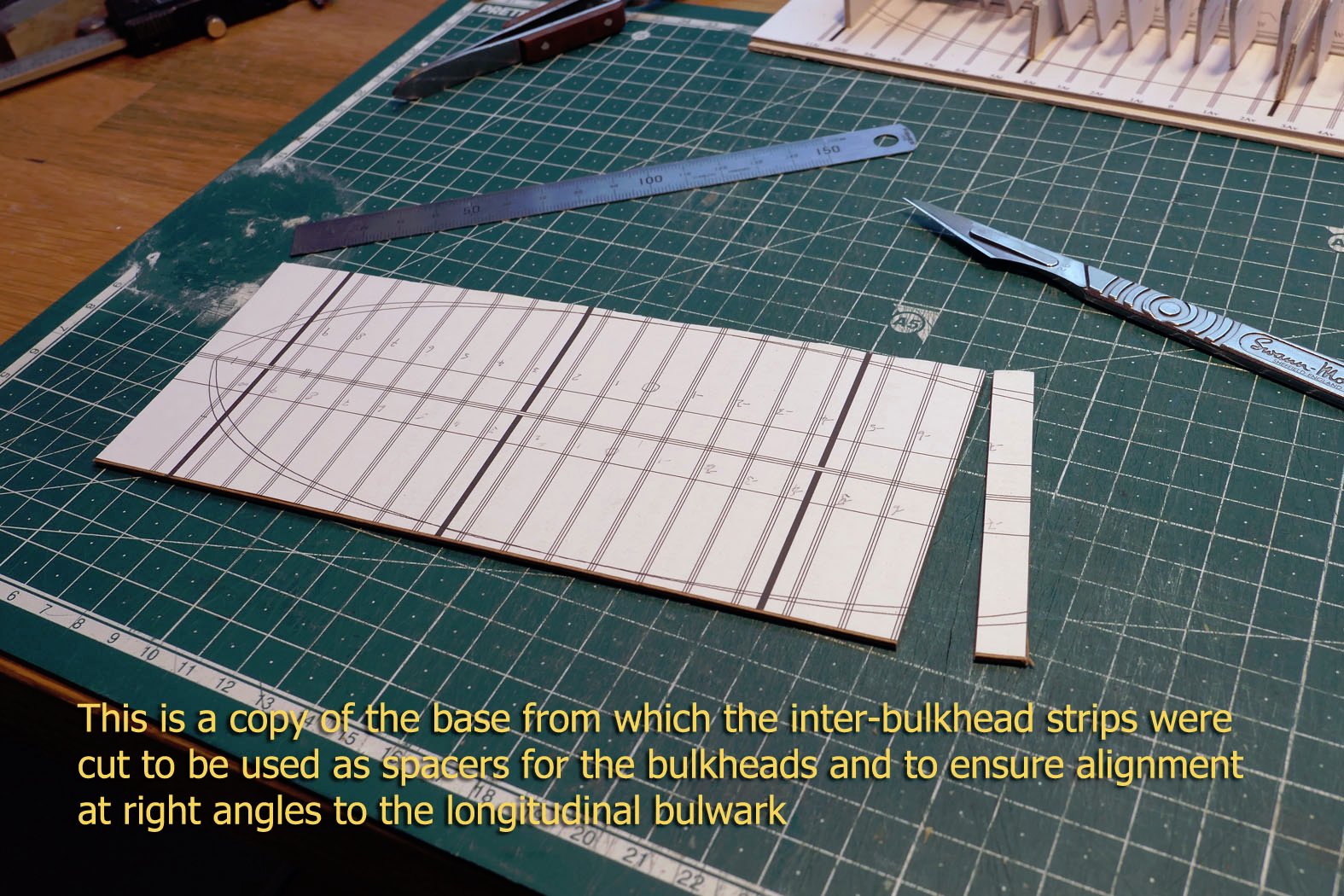
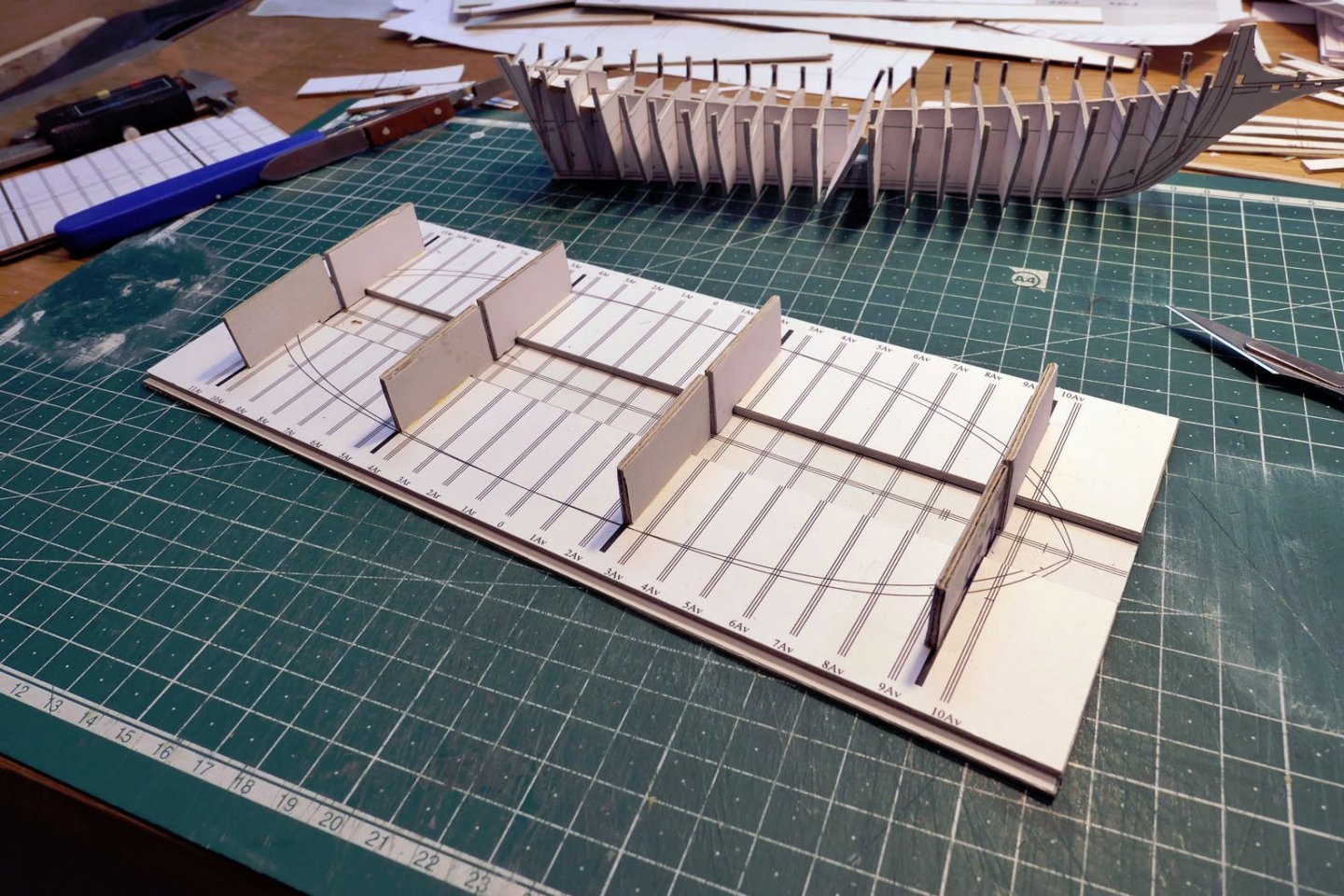
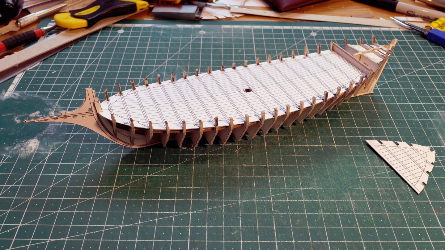
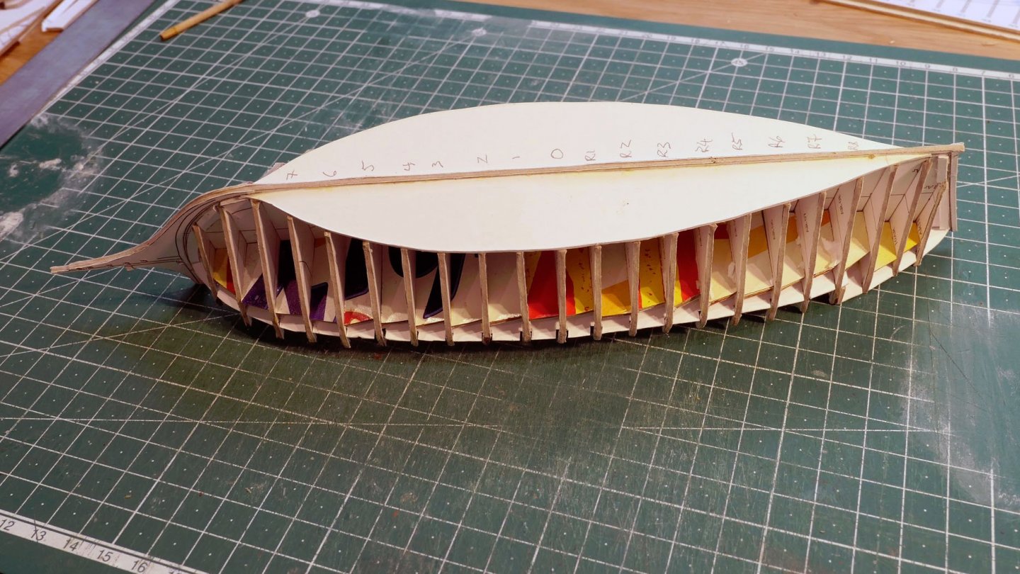
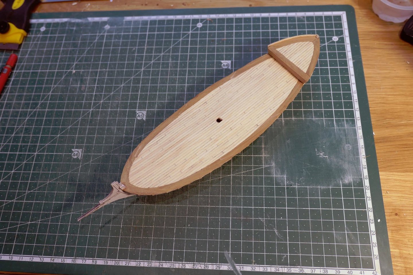
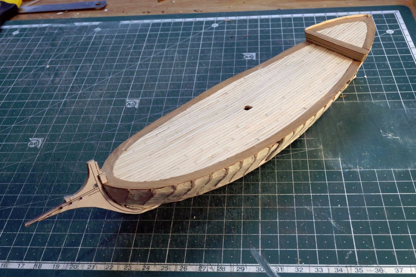
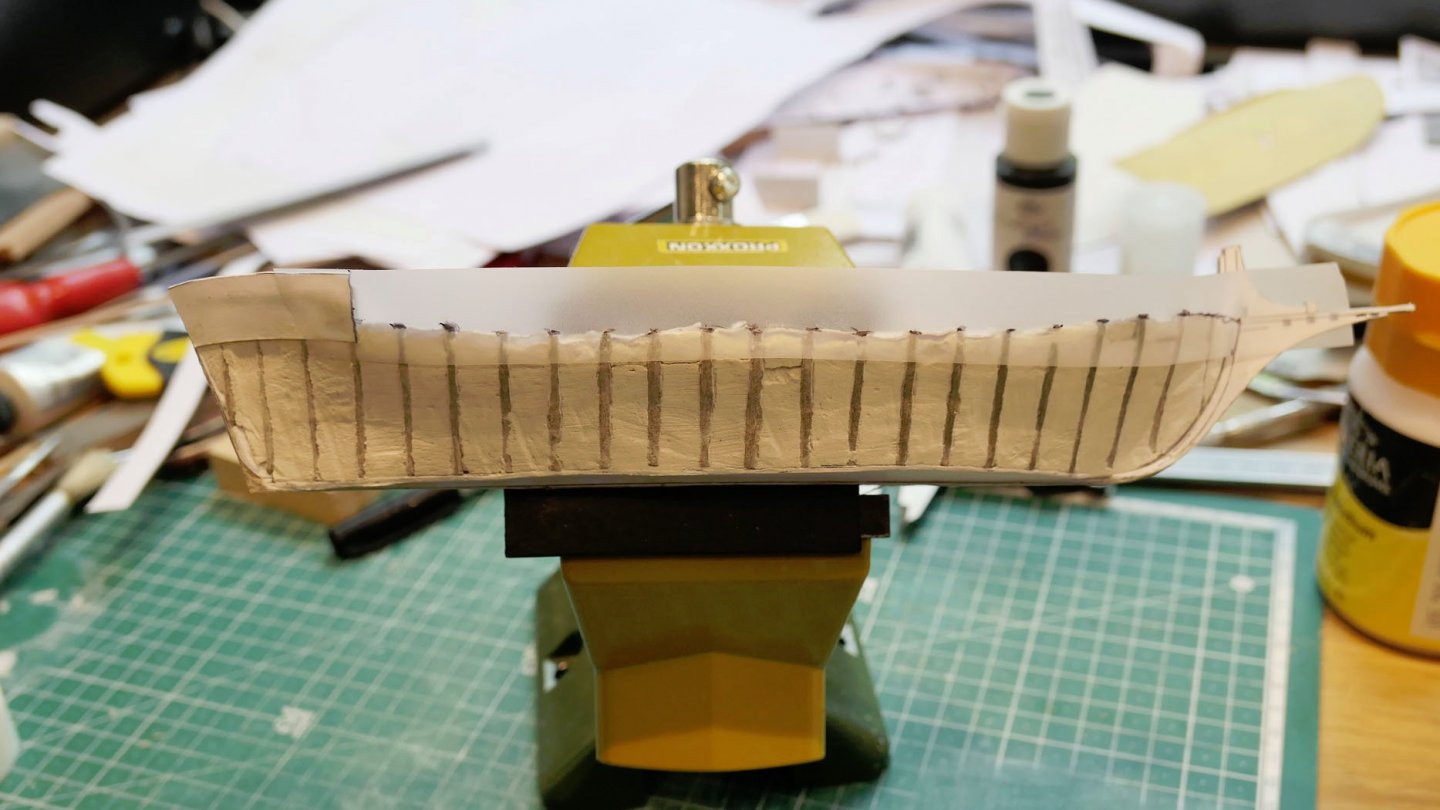
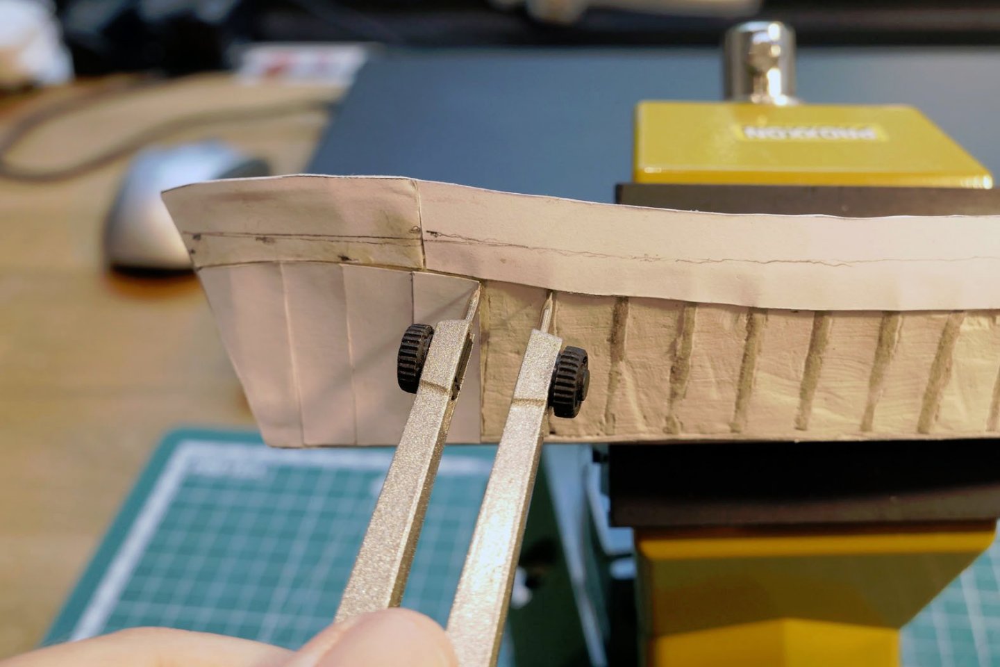
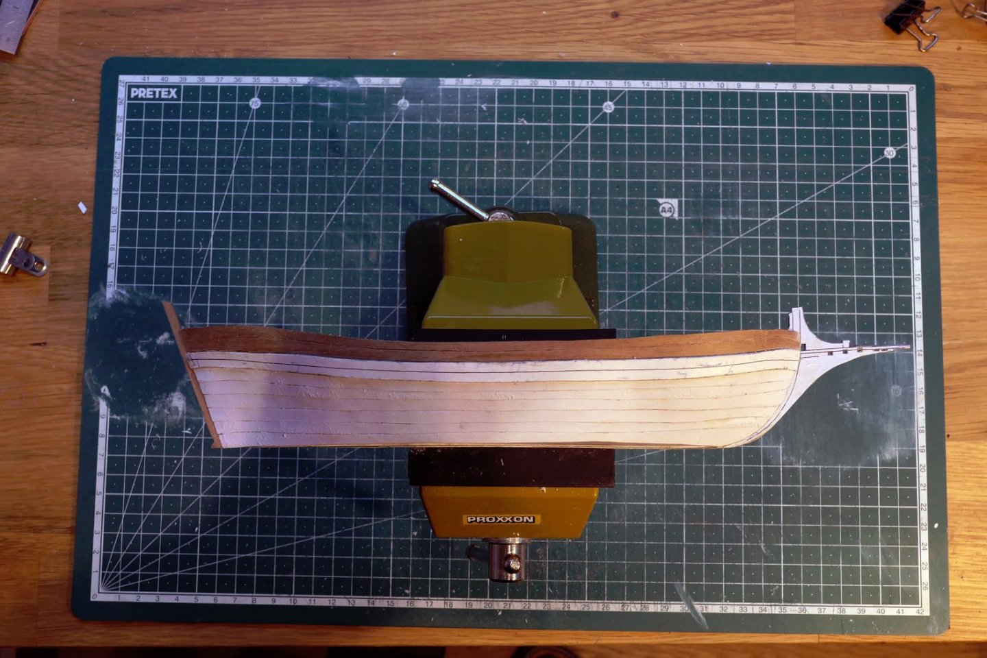
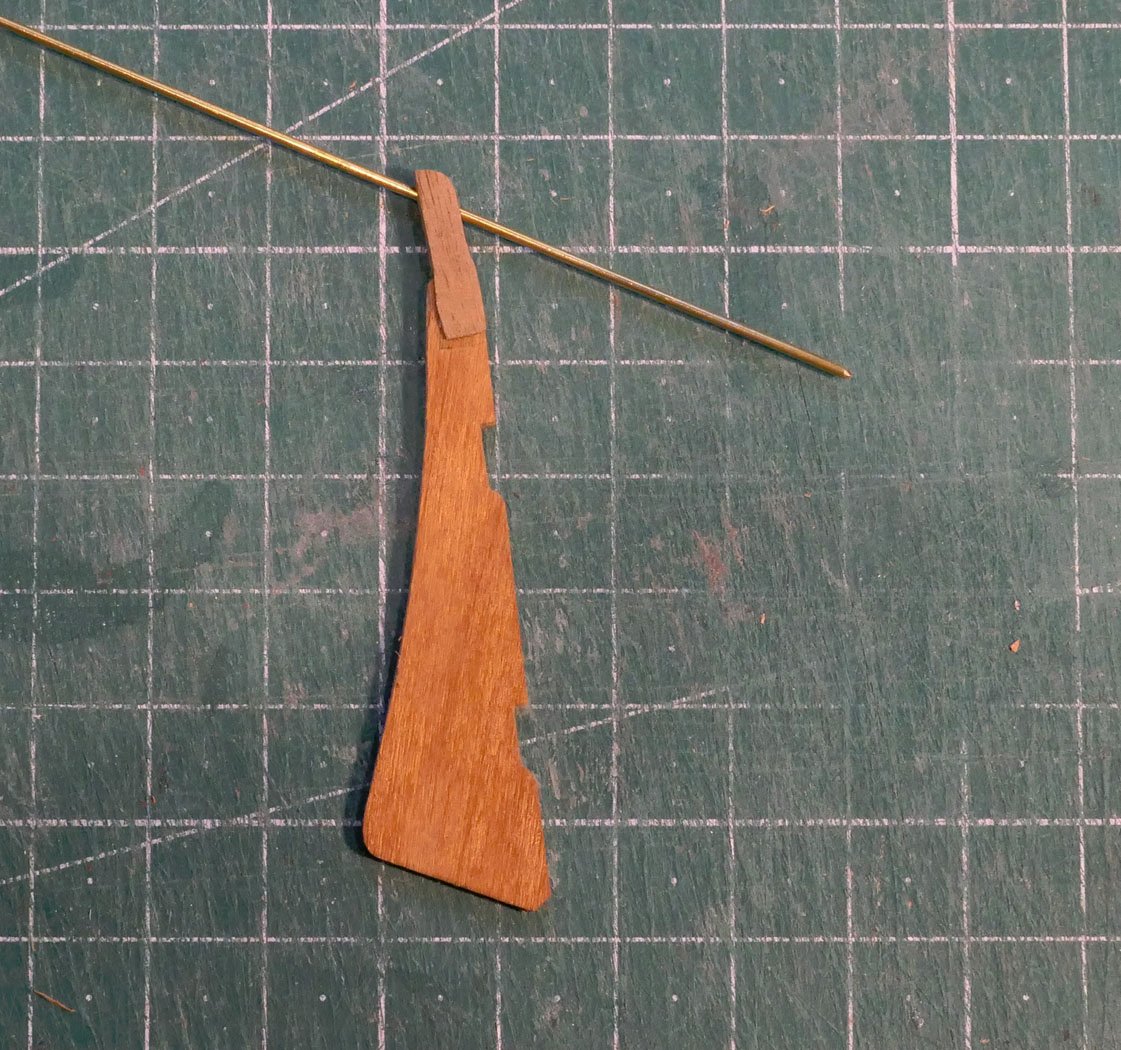
Thanks for all the likes, which I'm very grateful for as good wishes for the future outcome! I just hope you won't end up a little let down as for me it's been like starting all over again with scale and card. Both these require new skills and techniques which I'm still learning. PLANK ON BULKHEAD As the next stage of my apprenticeship, I wanted to try my hand at making a POB version of a ship based on the plans. In particular I wanted to see the possibilities of building the frame in card but finishing the planking and the rest of the model in wood. This definitely is a plus for a scale of 1:100, since the frames have very small sided and moulded dimensions: the frame sided measurement being only 1.2mm (moulded 3mm). I could have used the method of Javier Baron by making a mould, as done for longboats, but preferred the opportunity to do something new. There are advantages and disadvantages of making a model at a scale of 1:100, as opposed to the 1:48 at which the plans are drawn. The main disadvantage, of course, is the level of detail that can be provided. A quick look at the photos of M Fissore’s build at 1:48 provides amazement at the detail, finish and skills in making such a model. But bigger models require more wood and space. Smaller models are the reverse. One question is that of rope. The sizes at this scale should be 0.2-0.6mm. My smallest thread is 0.3mm, which means I have to drill 0.4mm holes for the sheaves. This is probably ok visually, but the problems for me come with making the smallest blocks while still retaining the shape of blocks. At 1:100, the smallest blocks would have to be 1.49 x 1.19 x 0.76. The smallest block I found I could make comfortably was 2.27mm long, which certainly looks a bit large for the blocks holding the tiller. I could try to buy manufactured blocks (e.g. photo-etched), but I like the challenge of making things myself whenever possible. I suppose I will just have to try harder in future, but for the moment I’m sticking to 2.27mm blocks. On the subject of detail, as usual I discarded the idea of treenailing as they would be next to invisible at this scale, and only displayed larger bolts, as for the bitts. THE FRAMEWORK I prepared a suitable holding frame from card and used the frame stations as sites for the bulkheads. So far, so ordinary. I used a copy of the base from which to cut the spacers between the bulkheads so they remained at right angles to the longitudinal spine. The stem, keel and stern were cut in card as one single piece, and fitted into corresponding grooves in the frames. I much regretted not making them from wood. Although I had strengthened all the parts with gesso, this proved inadequate to resist the problems of chafing, distortion and sanding during the handling of the model. CA glue might have been more effective, but I found even that not enough when I tried to use it on the tops of the bulkheads and the stem. The base for the deck was then installed. Followed by card plates for the flat bottom. My problems started when I tried to emulate those card modellers who fill between the bulkheads. It feels like I’m starting modelling all over again as I clearly botched it this time! But I put it all down to the necessary learning experience. I used a water-based filler made up from powder to fill the spaces between the bulkheads. This was supposed to avoid the problem of an irregular surface when I came to applying the sheets of card over the bulkheads to serve as a surface for the planking. I made the paste as thick as possible in order to avoid much shrinkage, but there were some essential problems which I failed to overcome. First was the contraction of the filler as it dried, making it difficult to have an absolutely flush surface to the hull. Second was the difficulty of providing an accurate base for the deck as it curved in both directions. Third was the discovery that the water from the filler distorted the card both of the deck base and the bulkheads themselves – making it difficult to keep them square to each other. This also resulted in making the timberheads distorted and expanded. This problem might have been avoided if I had covered the bulkheads with CA glue in advance. The gesso only absorbed the water. I think in future I'll go for filling with wood blocks as these can be shaped so much more easily. Finally, I came to realise that I had to leave a space for the mast, and this made filling of that area rather tricky, again rising to distortion in the framework. This is where the wooden parts of the build began. I started on the waterway, which I cut from 0.5mm thick pear wood. This would stand in contrast to the deck planking which would be from lime wood. This was followed by the deck planking, using 2mm strips of lime 0.5mm thick, so as to be close to scale as possible. After completing the waterways and the deck planking I moved on to pasting strips of card to act as the base for the hull planking. A strip of low-tack transparent tape was laid on which the outline of the top sides could be traced, and then cut out on some pear wood. The wales were made from card, again something I later regretted when it came to sanding as they proved very easy to fray at the edges. The hull planking was also made from card. This was ok until I tried sanding it. I found that my sanding produced a really dreadful surface for painting. It led me to understand why so many card modellers then use a plasticised laminate for the planking. More experienced card modellers have somehow cracked the problem, producing beautiful surfaces, but I have still to learn and practice much! I thus decided I would complete the upper planking in wood to make my life easier. In addition, because the sternpost was by then quite distorted, I replaced the card version with a wooden one for strength as well as appearance, since it would have to hold the pintles for the rudder. The rudder I completed the initial basic structure with the rudder, using a 0.5mm hole for the tiller. The photo shows the brass rod I used to check the angle of the tiller. I ended by making up the ironwork for the rudder in the usual ways. Till next time! Tony


- 41 replies
-
- 10
-
-
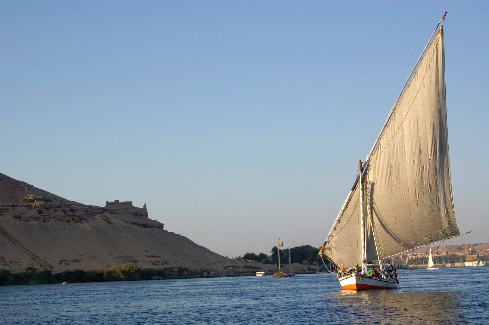
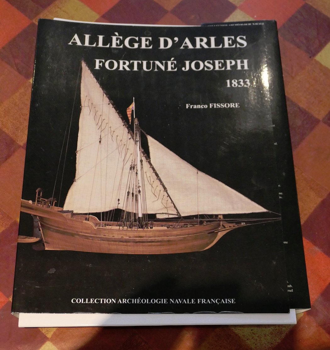
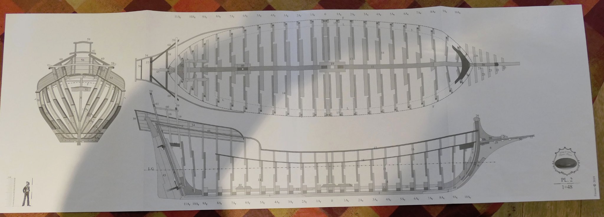
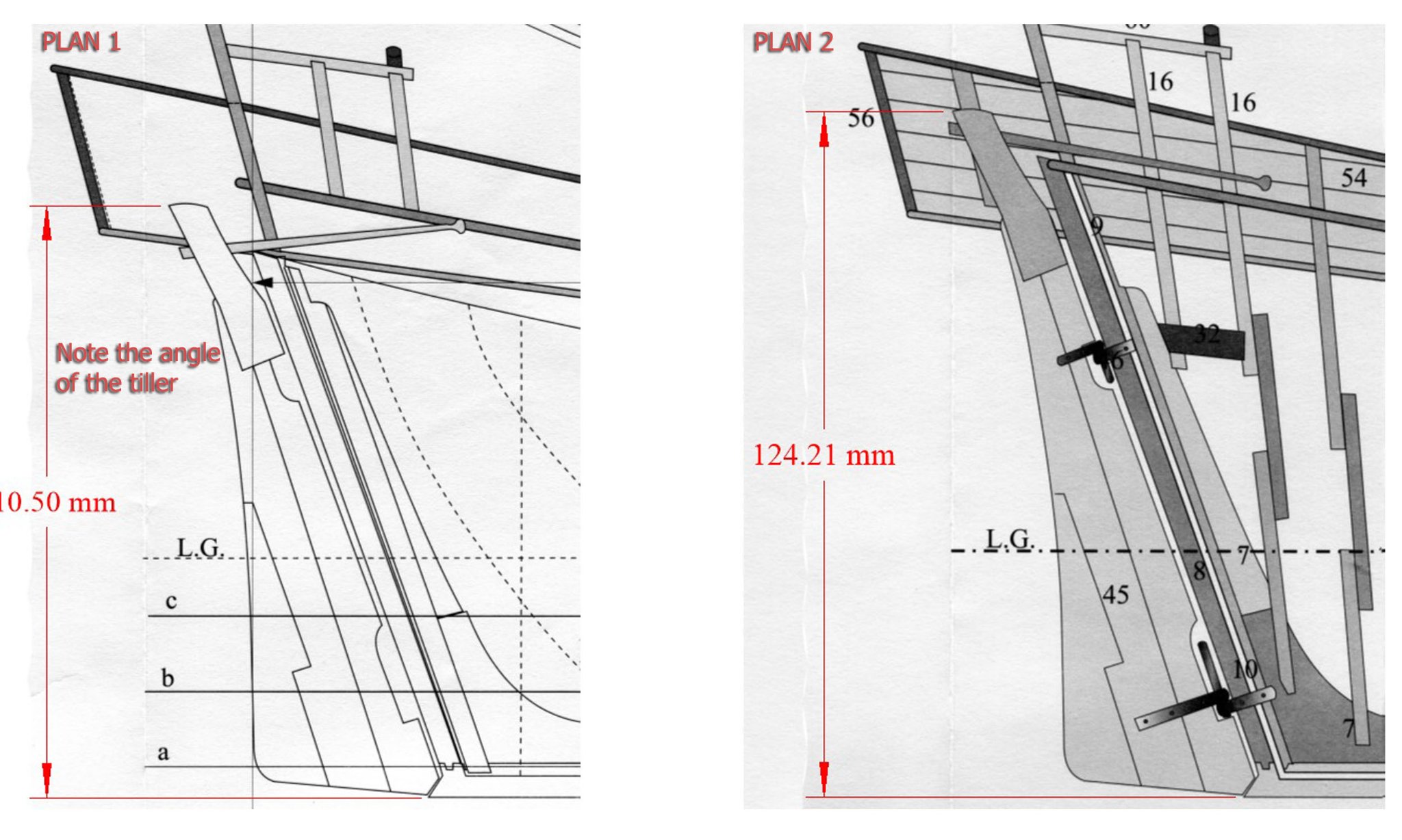
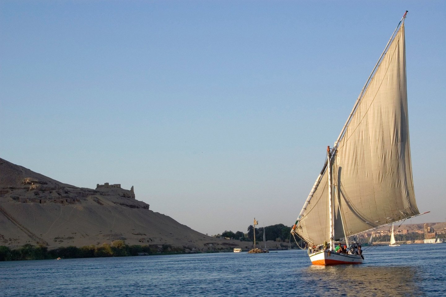
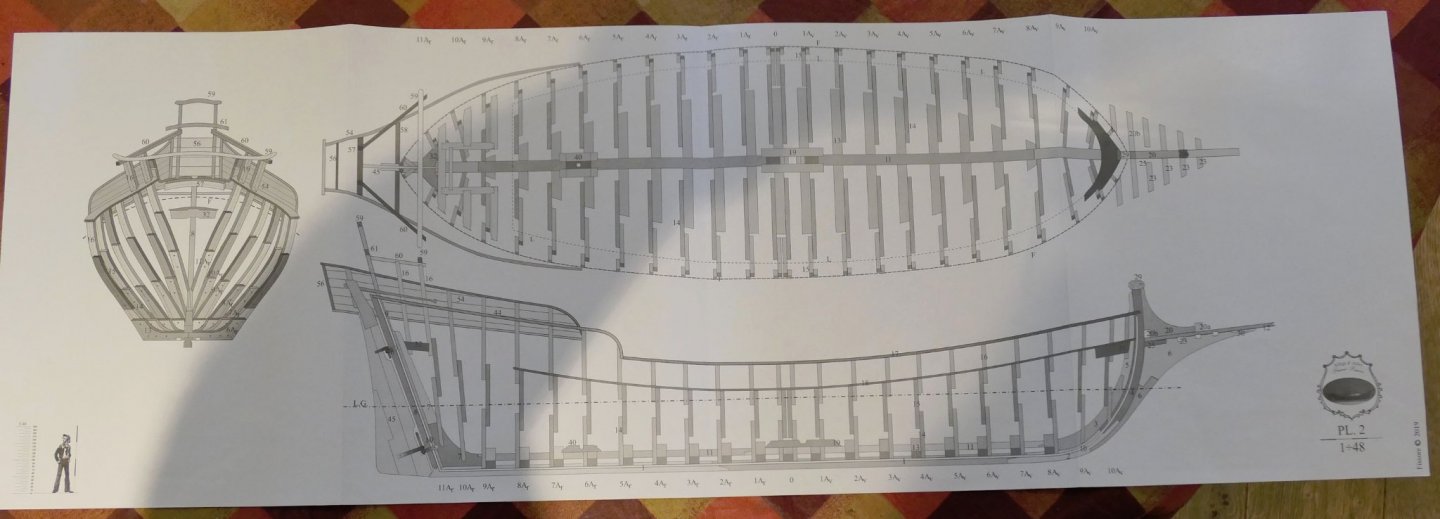
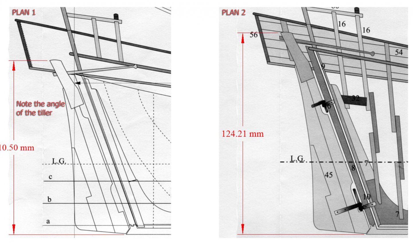
INTRODUCTION & RATIONALE I was given the Ancre monograph of the Fortuné Joseph, an Allège d’Arles (the English translation), and, as I was wondering what next to build, this looked like a good possibility. There were lots of variation to these allèges, or lighters, in the 19th Century, but all had in common their lateen rig and general shape. Ever since being taken on an Arab felucca on the Nile (the one in my picture below), I have been intrigued by the lateen rig. I haven’t been able to find any plans or construction details of a Nile felucca (if anyone knows of any, please do advise me), but this Mediterranean version seemed near enough and I liked the lines – so I decided to jump in and try my hand at a build. I have treated my previous builds as a kind of enjoyable apprenticeship, learning the different ways of approaching builds, experimenting with wood and card, understanding the various types of tool that can be used, and getting to grips with plans and CAD. In particular, I have tried to figure out what aspect of model-making interested me most: the type of model, the historical research, the level of detail, the level of skill, the level of accuracy, the general image, the balance between thinking and practical building, the presentation of the model when finished. My first realisation was two-fold: I am far more interested in working or merchant craft than in warships, and completion of the model holds very little interest for me. I simply don’t know what to do with the completed models, other than give them away. The second realisation was that, partly because of my lack of interest in the completed model, and partly because I have nowhere to place them when finished, I would like to explore the creation of small-scale models. I had seen Javier Baron’s 1:200 build of the Allège, and thought that that scale would be an ultimate aim for me, but for the moment I thought I’d focus on a similarly large scale. After seeing kondzik’s build of the card kit of the Allège d’Arles published by WAK, I bought the card kit and built it just as far as the completion of the hull and its planking. This kit seems to be very similar to the allège in the Ancre monograph (although there are lots of differences – such as the dimensions of the quarterdeck) so this would give me not only a good idea of the overall lines and problems that might have to be overcome, but also an insight into the use of card to scratch build a hull. I had had the idea of building hull bulwarks just with card and finishing the rest of a model with wood, as I’d seen someone do that with a Shipyard card kit of the Alert. At first I wasn’t going to make this into a log for a model forum since it really was an experiment just to explore the possibilities as I will explain further on. However, I decided in the end that there may be enough interest in reflections on the Ancre publication to justify a log of my build that is definitely full of mistakes, and a rather ramshackle construction and finish. For these I apologise. The build of the card kit also gave me a little experience with using filler on a card model to provide a good surface for the planking, as so many card modellers have said that without filler it is quite difficult to avoid depressions in the curve of the hull. I followed Ab Hoving’s suggestion of a standard water-based filler. THE PLANS Unfortunately, the monograph and plans drawn by F. Fissore of the allège (as others have noted with builds of the Gemma and S.Caterina) do not match the excellence and comprehensive nature of the monographs from other authors published by Ancre such as Jean Boudriot and Gérard Delacroix. Thus this monograph has a very different approach: the usual detailed analysis of the plans in the monograph is instead merely a list of the parts shown in each plan, there are no scantlings provided for any parts or rigging (we are not even given the dimensions of the keel), and the guide to the building of the boat is almost entirely in photographs of the author’s build (most of which are very small, of poor resolution and thus hard to demonstrate detail). This approach might not be so worrisome to those used to working from plans. It should also be pointed out that the section on rigging is good, especially given the fact that each aspect of the rigging is given its own illustration in the manner of Lennarth Petersson, and this will be discussed later. Another big plus is that the plans are laid out on long pages whose height is that of an A4 page in portrait mode – making it easy to photocopy and then stitch the pages together. [The dimensions of this photo have been modified to avoid replication.] However these positive aspects are offset by lots of errors in both monograph and plans which need correction. My first realisation of problems with the plans came when I compared Plan 1 with Plan 2. They showed the rudder and tiller entirely differently as follows: In this instance, Ancre immediately responded to my request for clarification and they sent me a pdf of a revised Plan 1 which corrected this anomaly – Plan 2 showing the correct dimensions. The anomaly made me study the monograph more intensely in case there were further problems which I needed to bring to the attention of Ancre. I soon found lots. There are four main types of problem: 1. The plans are inconsistent with the method of building shown in the photos of the monograph. (a) There are many details in the photos of the actual build which are not shown in the plans. This led to my having to undo some of the work I had done when I finally spotted the often important detail. One of the many examples is that there are inconsistencies about the number of beams running under the bowsprit fore timbers. (b) Less importantly, the plans show the frame top timbers extending to the top rails throughout, but the pictures of the build showing the method of construction show the frames ending beneath the lower waterway with the timberheads being constructed separately and fitted into square holes in the waterways and rails. The confusion is worsened by the fact that the plans of the frames themselves do not show the position of the ends of the top timbers at all accurately. Of course, once this is understood, the experienced modeller will be able to adapt their thinking and modify the plans accordingly, but it is at first very confusing when comparing photographs with the plans. 2. The second type of problem is that the plans of the frames are incorrectly drawn, especially in Plan 4 of the frames which shows the floors of each frame extending only to the top of the keel rather than to the top edge of the rabbet. Once this has been spotted by the modeller who has been careful to examine the measurements this again will not be a problem. The base of the floors has simply to be extended by a few millimetres (depending on the scale that will be used). 3. The third type of problem is that of inconsistency between the plans. Thus in some the waterways are shown correctly, and in others they are simply not there. There are many other similar discrepancies. 4. A fourth, more irritating problem, is that the numbers on several of the plans do not match the text of the monograph, nor are they consistent on different pages of the monograph. On some of the plans the numbers are duplicated, with different parts having the same number, on some the parts are given the incorrect names (e.g. a rudder blade is given the same number as a top rail; the keel and the sternpost are both referred to as the sternpost); and some parts are given no reference at all. Some of these difficulties may possibly be due to the very poor translation into English (some pages are not translated at all from French, which is itself a translation of the original Italian) but obviously the experienced modeller will be able to manage once aware of the difficulties. All of these are a great pity as excellent models of the Gemma and S.Caterina (both plans by Fissore) have been built (although they do mention but do not detail the difficulties they faced with the plans), and the ships themselves have great attraction. M.Fissore himself shows photos of the builds of his various models including his own of the allège (at Archeologia e Modellismo d'Arsenal) and it is well worth the visit as the photos there are far, far clearer than in the book). I have written a fairly detailed list of these various problems and submitted them to Ancre for consideration by M. Fissore, so it may be that future editions of these plans and monograph will be made more amenable for a wider range of modellers. A very similar boat, La Diligente, which was a lateen Navy messenger boat of the 1750s, whose monograph is published by Ancre and written by Gérard Delacroix & Hubert Berti, has the same level of complexity but is not only incredibly detailed and thorough together with complete scantlings: it also provides a set of plans that will allow the less experienced modeller to make it POB rather than POF. In the interim, as long as one is aware of the problems with plans and monograph, the experienced modeller will be able to use the correct body, sheer and breadth plans on a corrected Plan 1 as the basis for their model. I'll be adding stages of the build over the next few weeks, so I hope it will be of interest. As usual, don't hold your breath! Tony

- 41 replies
-
- 13
-


.jpg.4bb065512253696d3a6d5bb5f7b4a17f.jpg)


annot.jpg.0f3eb59df5135818065e39c7dde13829.jpg)
annot.jpg.c934e4e80954b6bd7e5ad783dca6b943.jpg)