tkay11
-
Posts
1,829 -
Joined
-
Last visited
Content Type
Profiles
Forums
Gallery
Events
Everything posted by tkay11
-
 What fun, Sarah! This one really brought a smile. I much look forward to the rest. We'll have to keep a watch on Sjors' translations though - he might have the temptation to slip in a joke or two! Tony
 -
I've used Liberon wax filler sticks used in furniture repair. It's really easy to apply and wipe off. These wax fillers come in a lot of shades so it's easy to achieve the right level of difference from the wood of the planks, and provides a subtle effect. I had this tip from Daniel when he was on MSW 1.0 but I've seen a few others do this as well. I did try melting it into the holes but it turned out to be just as easy to scrape a few fragments off and wipe them into the holes. Tony
-
It used to be owned and given free by Google. It was then sold to Trimble who have a two-tier system. There is a free version and a version you have to pay for which has more features. You can find it by searching for 'SketchUp'. Wikipedia has an entry for the programme. If you want a direct link to the download site, click here. I believe most CAD programmes will do the same. Tony
-
Of course you are right, Carl. There will be a market for printed books for a long time. I myself like reading from a printed page last thing at night in bed. However I am trying to make the case that the market for ship modelling books also needs to include the need for stuff that can be seen on screen and only the relevant pages printed if needed. Part of that is the need for lower cost material, but to my mind there are also other factors. You correctly point to the fact that it is something habitual to read a book. However people are now coming into ship modelling whose main experience has been use of computers, video games and screen-base phones. A very interesting example of this is the complete build of the Cutter Alert only with SketchUp (a CAD-type programme). If you go to the CAD forum you'll see the skills of 'SketchUpModeller' whose only build is in SketchUp. WIth this new, exciting and highly skilled generation (and SketchUpModeller has expressed an interest at some time in the future in wooden modelling) it surely would make sense to have low cost screen-based materials to use. Apart from that, I am very happy to read material onscreen even if only for short periods. As I said, I can then print off what I need for constant reference. I certainly wouldn't take away from the sheer pleasure of a beautifully printed book. The question is how much that is of generational and cultural conditioning? I don't know the answer to that. Tony
-
We still haven't had a reply about the possibility of pdf versions of books (or even e-books) whether or not they are published in Europe or America. The world is changing in the way we use books. A huge amount of my reading, research and study (even for my mainline job and for medical research) is online now. I don't think we'll get over high costs of shipping of heavy books (in fact I'll be waiting for an American friend or colleague to bring me books I may want from the USA). Printed medical textbooks are now in decline, but of course there is still a large market for them in countries with low internet access. I should imagine a high proportion of people involved in ship modelling are in countries where internet access is very high. More important is whether or not people who publish books about model ship building can focus now on a more economic format online. The quality of the pictures would in fact be better on line than in a printed book (screens have a higher dynamic and colour range than is possible with printing). This site has itself shown the redundancy of a lot of printed books. The books I am really interested in in relation to ship modelling are the 'how to' books. Not expensive paperweights that will essentially remain on the shelf once looked at. The SeaWatch books fall into the category of 'how to' books. Why they should not be in a cheaper online format defeats me. The costs of publishing would be lower, the number of people who purchase potentially greater, the profit margins left substantially the same or even greater since there are never any publishing re-runs to fund. I do understand I may be naive about the costs of online publishing, but then the point of my post is to understand why it may be difficult to switch to this form of publishing. Tony
-
It's certainly not out of print. I just bought a copy from Ancre which was delivered in very quick time. Note: no shipping charges in the EU. However, having studied it, I would think it is more valuable to the advanced modeller who already has some experience in using the techniques and tools portrayed since these are very much in shorthand in the book. In terms of practical suggestions on individual steps in the process of building a model at my stage of the game, I think my main sources, in order, have been (1) this site with its enormous reservoir of help and demonstration from people who are both generous and selfless, (2) 'Historic Ship Models' by zu Mondfeld, (3) Underhill's two volumes on Plank on Frame models (definitely only second-hand now). The other books I have found useful at my stage of learning have been the Anatomy of the Ship series on the Cutter 'Alert', and George Bandurek's book on Super-Detailing the Cutter Sherbourne (which used to be a log on this site). I also wasted money on about three other books which gave almost no detail or instruction and were pretty much just pretty pictures -- or the level of instruction was so basic as to make me sigh with frustration. All the same, I am happy I bought Frolich's book and I do use some of the suggestions he makes already (e.g. the building of a ship's boat -- although I am supplementing that with much better detail from this site). But the fact is that when I want to look at some of the detail of each step of the construction I have found the resources on this site by far the most valuable. Please bear in mind these comments are only those made by a novice builder. It may well be that I come to appreciate the value of Frolich's book much more as I progress. Also others will have their own priority list of resources -- especially as they may be coming to the subject with a great deal more practical experience than I have. If you can get a second-hand copy of Frolich and are at the same stage of the game as I am, then it truly is worth having -- if only to gawk at the amazing workmanship he displays. On the other hand, I can say I am equally stupefied by some of the builds I have seen on this and other fora for free. To my mind, achieving such craftmanship is not only finding others to show you some of the tricks (which you can do almost entirely using the posts and resources of this forum), it is also the sheer painful slog of trying it all out for yourself. That is what I am finding, and equally enjoying. I suppose my bottom line is that if you are hard-pressed for cash, then think carefully and try and see a copy before buying books. They are very expensive! Tony
- 48 replies
-
- 4
-

-
- Bernard Frolich
- The art of ship modeling
- (and 1 more)
-
That was a real pleasure, Ray, to see the complete build. A lot of useful pointers for my Sherbourne which is a very similar ship. A beautiful model. I'm looking forward to the Diana. Tony
- 20 replies
-
- 1
-
-
- lady nelson
- victory models
- (and 2 more)
-
Just adding to the chorus. I'm delighted you could re-post as yours is a build I was following avidly. Tony
-
Thanks a lot for re-posting this, Jamie. I've just been dabbling in building my ship's boat, and as that meant doing a solid hull I've been interested in any solid hull work. Your work is really beautiful. I look forward to the rest and the tutorials as they come in. Tony
-
Hello Kester! I was wondering if you're going to post pictures of your Sherbourne. You've been so helpful on a lot of builds, I definitely would like to see yours. I think you used to have the title 'Sherbourne - So far so good'. But of course that link has gone with MSW 1.0. Tony
- 57 replies
-
- 1
-
-
- caldercraft
- cutter
- (and 4 more)
-
I am in total agreement with Klaus. There are bookshops in the UK that would handle this )for example, the Model Dockyard, or Pen & Sword). I am fairly sure model shops such as Cornwall Model Boats would also sell them. I would have bought books from Seawatch, but have been put off by the huge expense of the posting. Tony
-
It's wonderful that you have decided to re-post your log, Alexandru. I am just trying to build a ship's boat and I'd taken quite a few tips from your own build -- apart from the fact that your whole build is magnificent and inspiring. Thank you Tony
-
It's great that you decided to repost, Sumner. I was missing that log. It's been such a great help with my own build. Looking forward to the rest. At the moment I'm trying to build a ship's boat for it -- which has been another fun learning experience. Oh, I forgot to add. I saw after I posted this message that you've got much better tags than I. Very good idea to have the different spellings of Sherborn in light of the different names for the plans. Tony
-
It seems to have taken him from Dec 27 2010 to Feb 25 2011. I find it just as amazing that he can do it in such a short space of time. Tony
-
Thanks, Jay and Garward. Very helpful! Tony
-
Thanks a lot, Garward, for the tips. I've been thinking about how to use the Proxxon cutting discs to make such pieces, but the fact is I don't have a lathe and I can see how useful it is. Is your lathe one of the Chinese made ones? If so, which one, and have you been happy with it? I might buy one next year when I can afford it! Tony
-
That's an excellent explanation, Dave. Thanks very much for taking the time to enlighten me! It also explains why, when I searched Google for rope servers, the answers seemed to be entirely for archery. Tony
-
Sorry for my ignorance, but I'd be grateful if you could explain what a serving jig does and how it differs from a ropewalk. I'd then know if I would need to make one in addition to the ropewalk! Tony
-
Thanks a lot for reposting this, Caroline. I'm thinking about making the ship's boat, and your build has been very useful. Tony
-
I don't know if this is the right place to post it, but while researching builds of the Cutter Alert, I came across this very interesting build which really is a scratch build, but not quite in the usual way. It's based on the use of Sketch Up and is really just a CAD build, but it is done as though on site and stage by stage. You can see it at http://sketchucation.com/forums/viewtopic.php?f=333&t=33757&sid=f942299afdf93114ad1c504acb5c6417. Or, if you want to click, click here. Sorry if the topic needs to be moved! Tony
-
Another Rope Walk
tkay11 replied to michael mott's topic in Rope Making/Ropewalks's Rope Materials and parts resources
Very nice to see such detailed instructions. Thanks very much Tony -
Haha, Carl! That's now as far as I posted previously. Coming up at some time in the future: Cannon rigging Shot racks Deck fittings continued ...and... perhaps (if I am at all successful) building a longboat for the cutter. The trouble with this particular scheme is that I was following the build of a 1:48 Victory by someone from South America. In it there were some really nice ideas about building a small longboat using layers of MDF (Medium Density Fiberboard). The trouble is that build seems now lost for the moment and I am hoping the person manages to re-post it all. Nevertheless, I have drawn up plans for the longboat and have cut out the first overall shape. If you don't see any more posts in this build about a longboat you'll know I've not managed it! I also seem to have spent ages learning about cutting more accurately, making lots and lots of small parts, learning from other people's builds, etc. It's going to be quite a relief to get back to what is beginning to look like a boat! Thanks for looking in, Tony
- 269 replies
-
- 1
-
-
- Caldercraft
- First build
- (and 3 more)
-
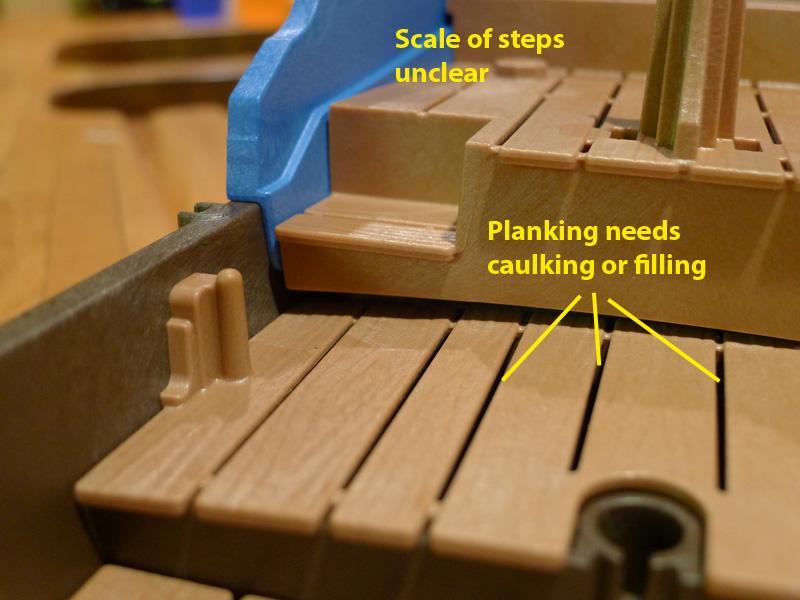
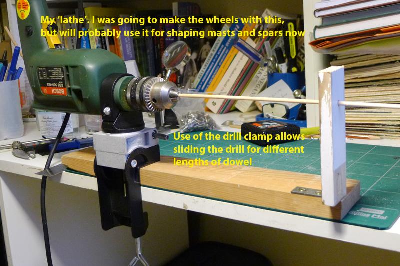
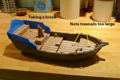
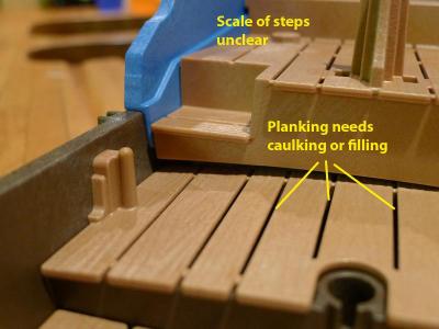
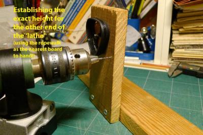
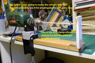
After the torment of trying to get the carriages right, I decided I’d start another build whilst thinking of how I might approach the building of the blocks and tackle for the guns. I settled on a rather rare pirate ship, whose plans have only recently been found. I decided I’d pretty much scratch build it from some plastic pieces I found in a box lying around in my daughter’s home. You’ll get the idea from the following pictures. At the moment I’m still struggling with the size of the treenails on the decking, and am having trouble scaling the stairway. Then there’s the vexed question of the planking. I decided that the lower decks would benefit from a lot more ventilation, and so left the planks separated along their length. However, I could be persuaded to fill them with some black paper or other caulking. You’ll probably notice the colour scheme, too. This is entirely in keeping with the fearless Captain Tony’s wishes to be noticed and recognised at once. The main thing, though, that I’d like help with from others on this forum, is to find out the name of the ship. I have the captain’s name, but unfortunately no mention is made (in any reference I can find) to the name. As part of my recuperation, I also made myself a pseudo-lathe using my electric drill in the same manner others have used on this forum. I had been intending to use it to make wheels, but in the end decided just to stay with the kit wheels. I am sure it’ll be useful for the masts and yards. Tony
- 269 replies
-
- 1
-
-
- Caldercraft
- First build
- (and 3 more)
-
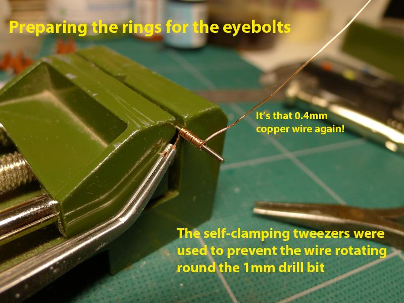
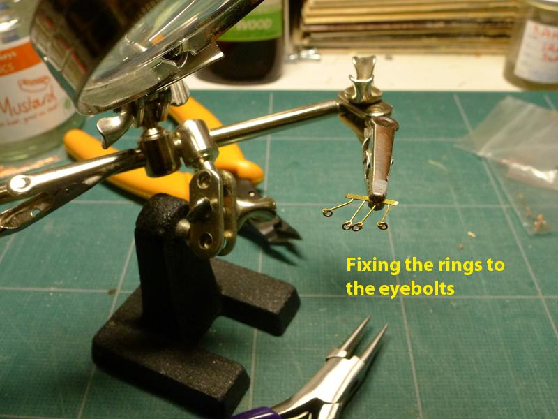
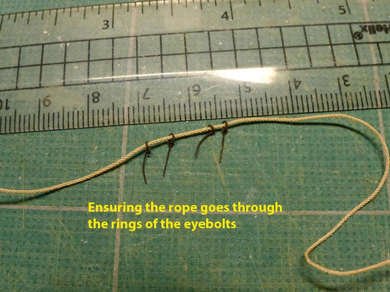
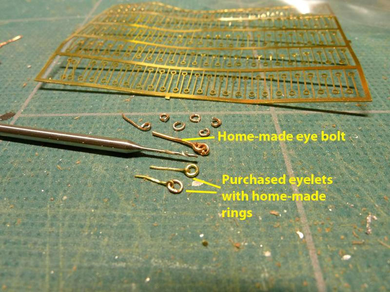
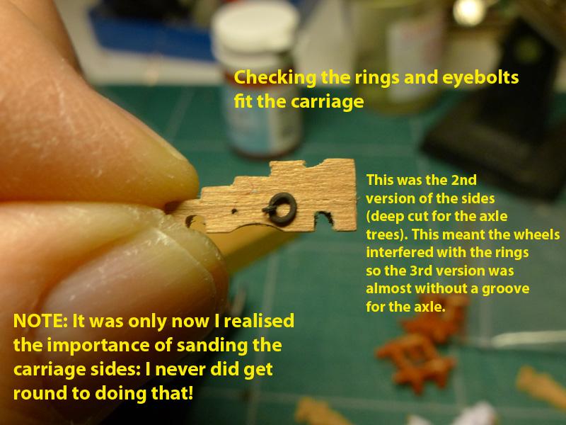
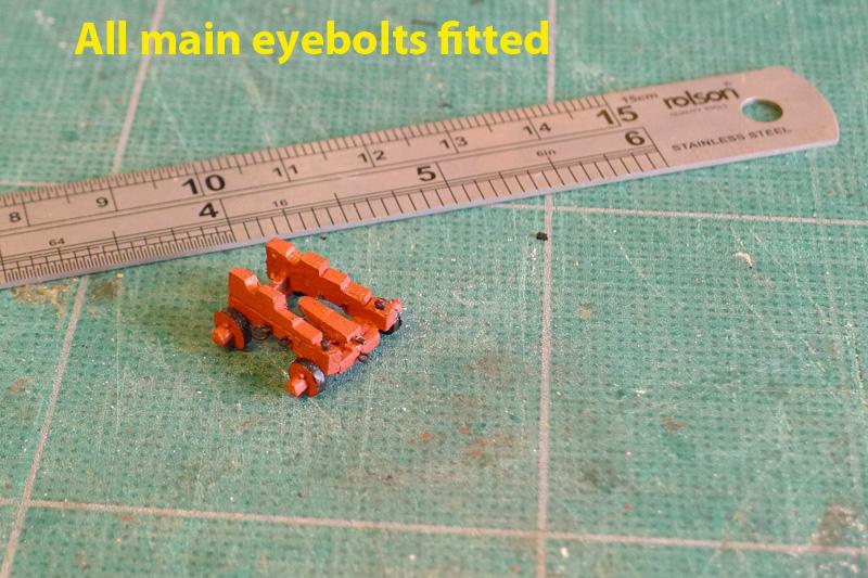
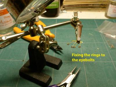
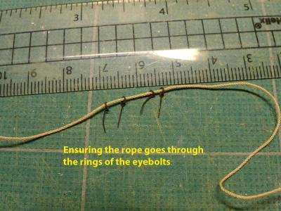
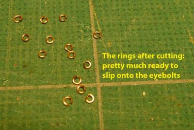
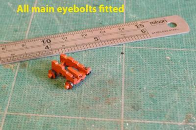
The carriages then had their eyebolts put in. At first I tried to make the eyebolts myself, using 0.4mm copper wire, but the results were too big and too rough. So I resorted to buying a pack of 0.3mm brass etched eyelets after a hint from Dirk/Dubz who did the same. These are really great! All I then had to do was to make the rings – which I did as so many have done, by winding 0.4mm copper wire round a 1mm drill bit, then cutting off the rings using the side-cutting pliers. I used brass blackener, as usual, for all the rings and eyebolts. This now leaves me with the rest of the gun tackle to make and the blocks to hold the ropes. That’s going to take me quite some time as new skills are required! Tony


- 269 replies
-
- 1
-
-
- Caldercraft
- First build
- (and 3 more)
-
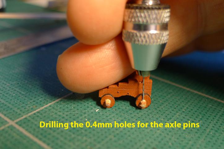
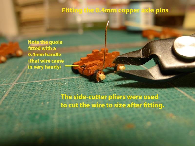
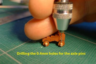
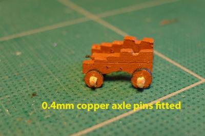
After the wheels were put on, the axle ends were sanded down to 1.3mm from the wheels, and 0.4mm holes were drilled to accommodate the axle pins. The axle pins were made of 0.4mm copper wire, snipped off by some really excellent (but amazingly cheap) side cutting pliers of the type used for printed circuit boards. The axles were then painted. Tony

- 269 replies
-
- 1
-
-
- Caldercraft
- First build
- (and 3 more)