


tkay11
-
Posts
1,822 -
Joined
-
Last visited
Content Type
Profiles
Forums
Gallery
Events
Posts posted by tkay11
-
-
5 minutes ago, drjeckl said:
She's stunning, yet casual.
Gosh, John, that's very nice of you. It's also exactly how I would describe my own view of the build. Well, maybe not quite stunning.
Tony
- Edwardkenway and mtaylor
-
 2
2
-
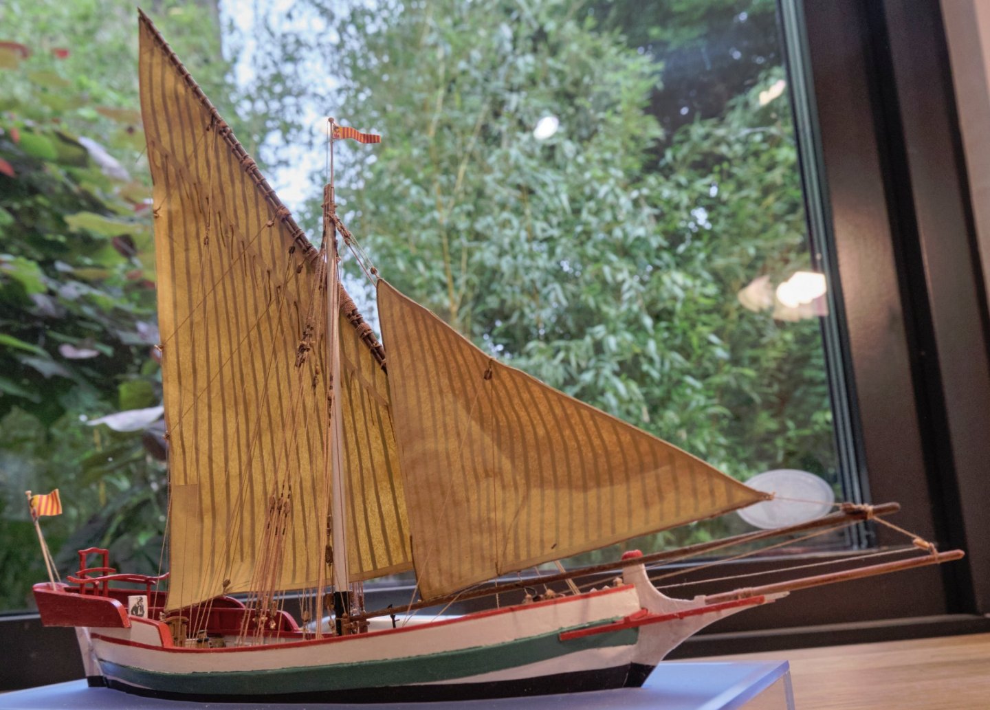
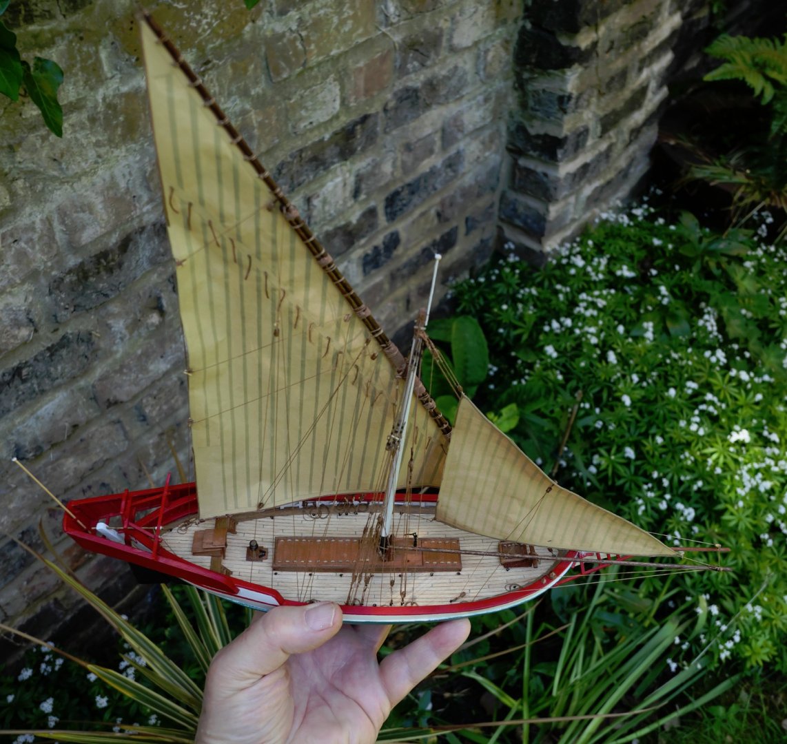
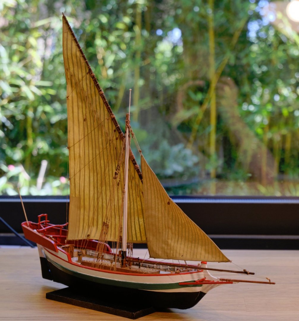
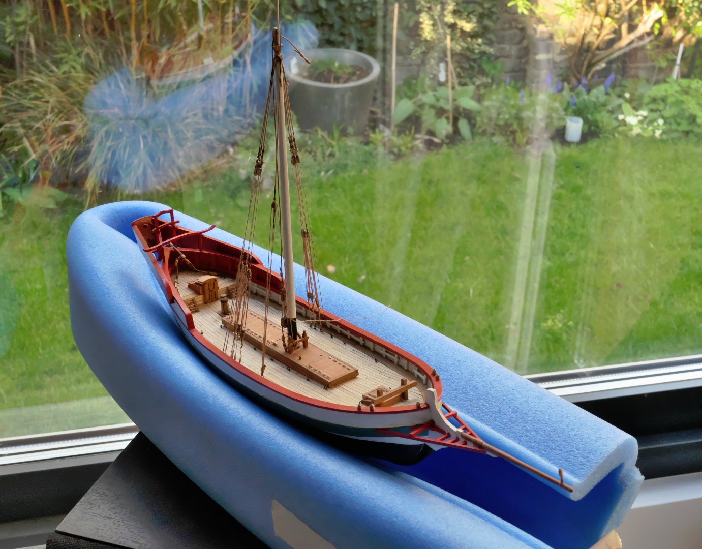
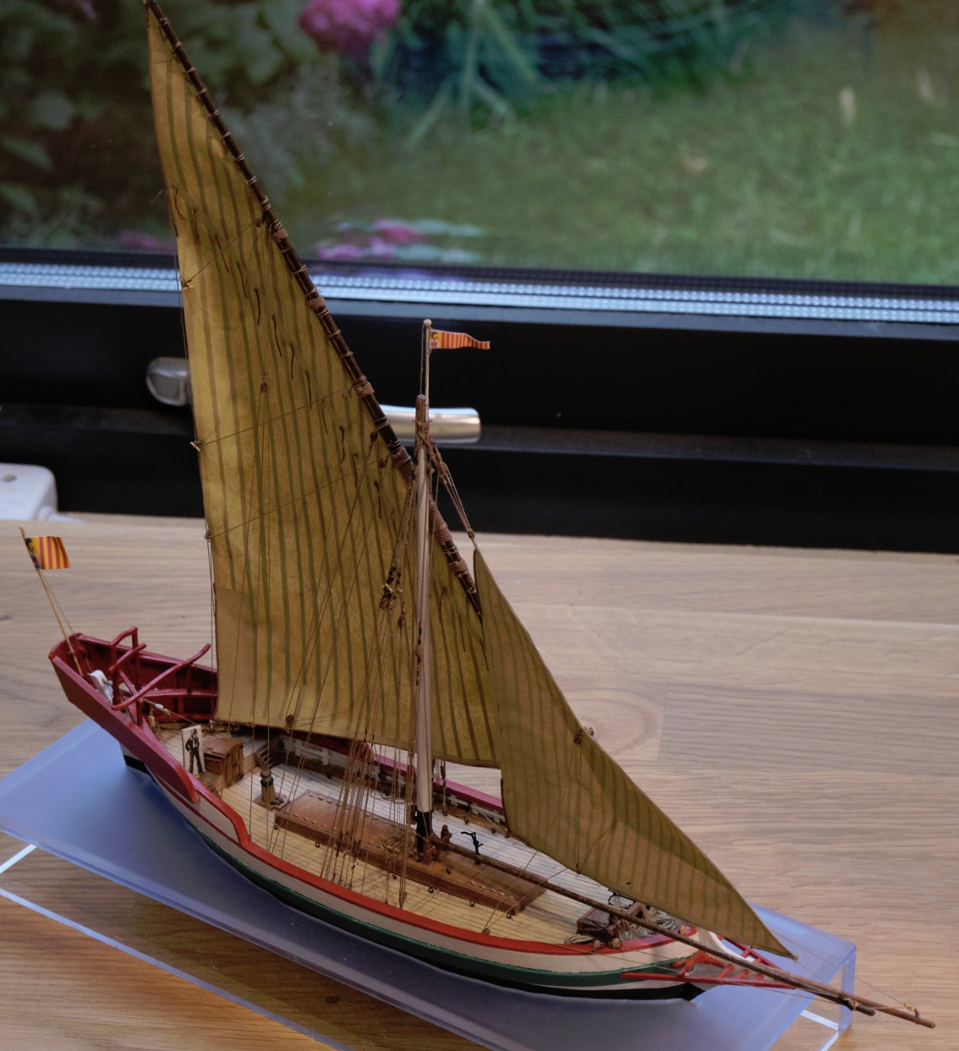
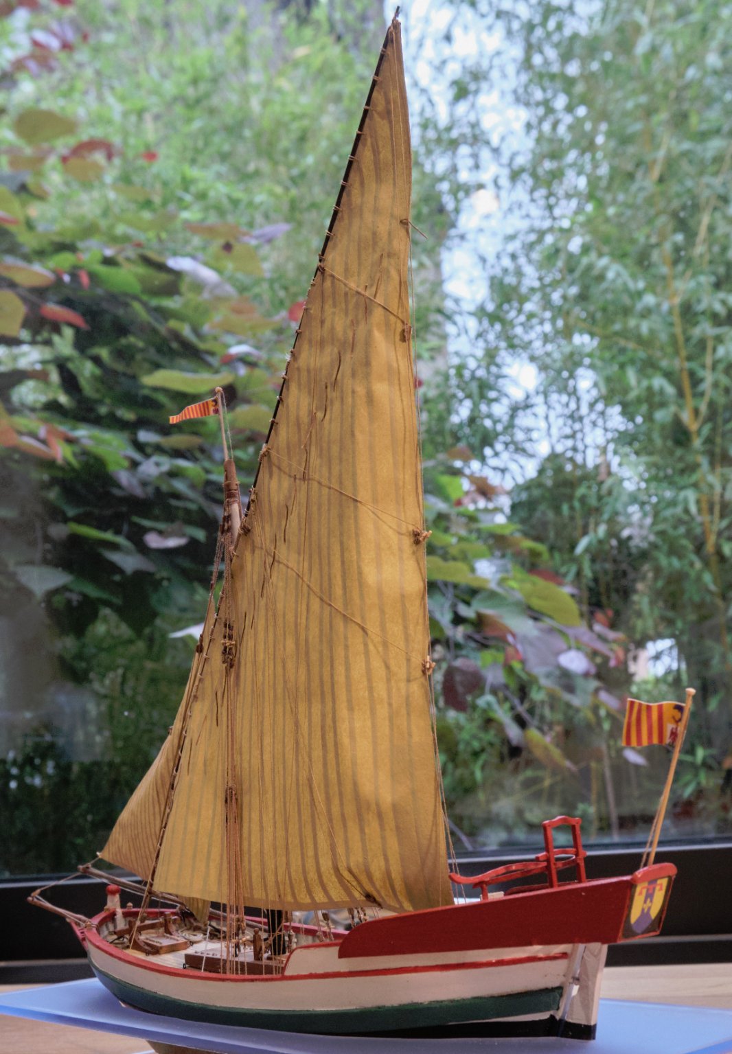
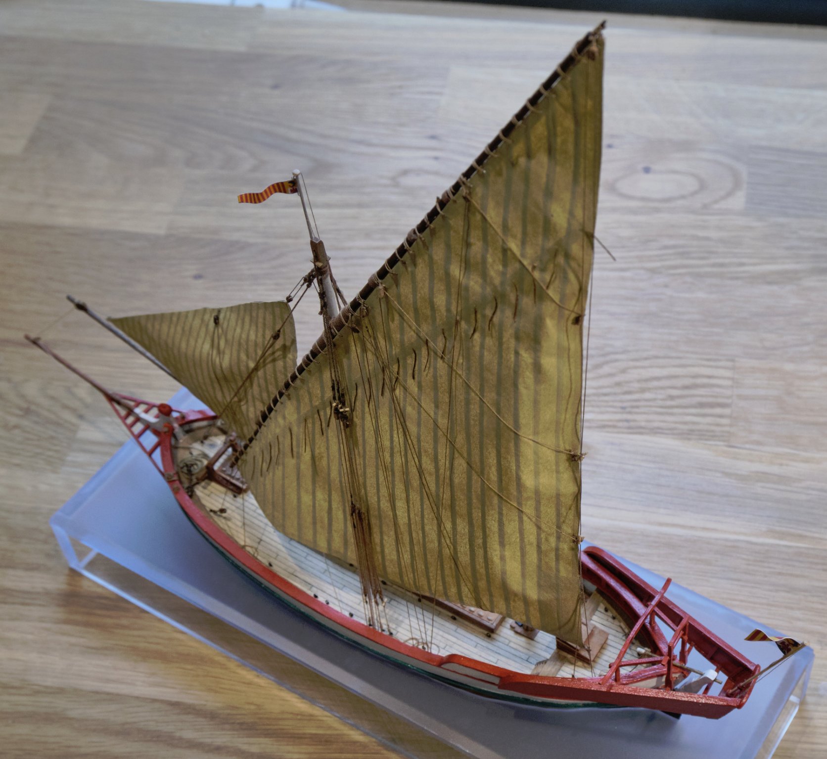
I decided to have another 'waterline' model in a perspex/acrylic stand. The top is acrylic blue, the sides plain so as to see underneath. It's to make me think of a clear blue Mediterranean sea.
I've now completed this model. As with previous models this was more of a learning exercise to look at (1) what it is to work at a smaller scale (not quite the 1:196 some modelers achieve and certainly not nearly as good as those who have worked at 1:96); (2) seeing if I can improve working with card; (3) practising with an airbrush; (4) continuing to try to improve working with a lathe and making blocks.
After completing it, I can see I have a long way to go before I can be satisfactory in any of these areas, although there is some improvement.
(1) My main concern is especially with the sails. I can't seem to make them retain their shape in the wind even though I used dilute PVA to stiffen the paper and a hair dryer. Part of the problem was maintaining the tension in the ropes without a real wind to keep the sails in position (perhaps wire is the answer). Then there is the fact that the left side of the sails is left bare as the bolt rope is fixed to the right. I shall try working with cotton voile next time and sewing on the bolt rope.(2) I don't think I'll ever try mixing card with wood again, and will stick with just wood and metal.
(3) Although I used a satin varnish to mix with linseed oil and white spirit as a finish, it remains too glarey under artificial light.
(4) I found that by making the ropes to the correct diameter, the appearance seemed very meager. I now understand why the advice is sometimes to go with appearance rather than correct dimensions. However, that brings with it the need to make blocks bigger than they should be. Also, using cotton thread without waxing it or singeing the fluff, the ropes have a very ragged appearance.
(5) The paintwork. Ouch! The poor waterline and edging of the card wales. I don't want to repeat that!
(6) Finally, it is clear I need to spend more time sanding the wooden parts.
All the same, I do like the general appearance of this allège, and am pleased to have done it. It would make a great model in more experienced and better hands.
It was also a kind of review of the Ancre monograph. In summary, I'd say that in comparison with other Ancre monographs (1) the explanations and translations were inadequate; (2) the plans needed very careful checking as there were plenty of inconsistencies and some mistakes (so far the plans I have worked with from Ancre or studied have been of a much higher quality); (3) very poor quality of the photos, which often were also poorly taken from the point of view of knowing what was shown. However, the rigging diagrams and notes were very good. Understanding this monograph is certainly helped by looking at the detailed photos on Fissore's own site.
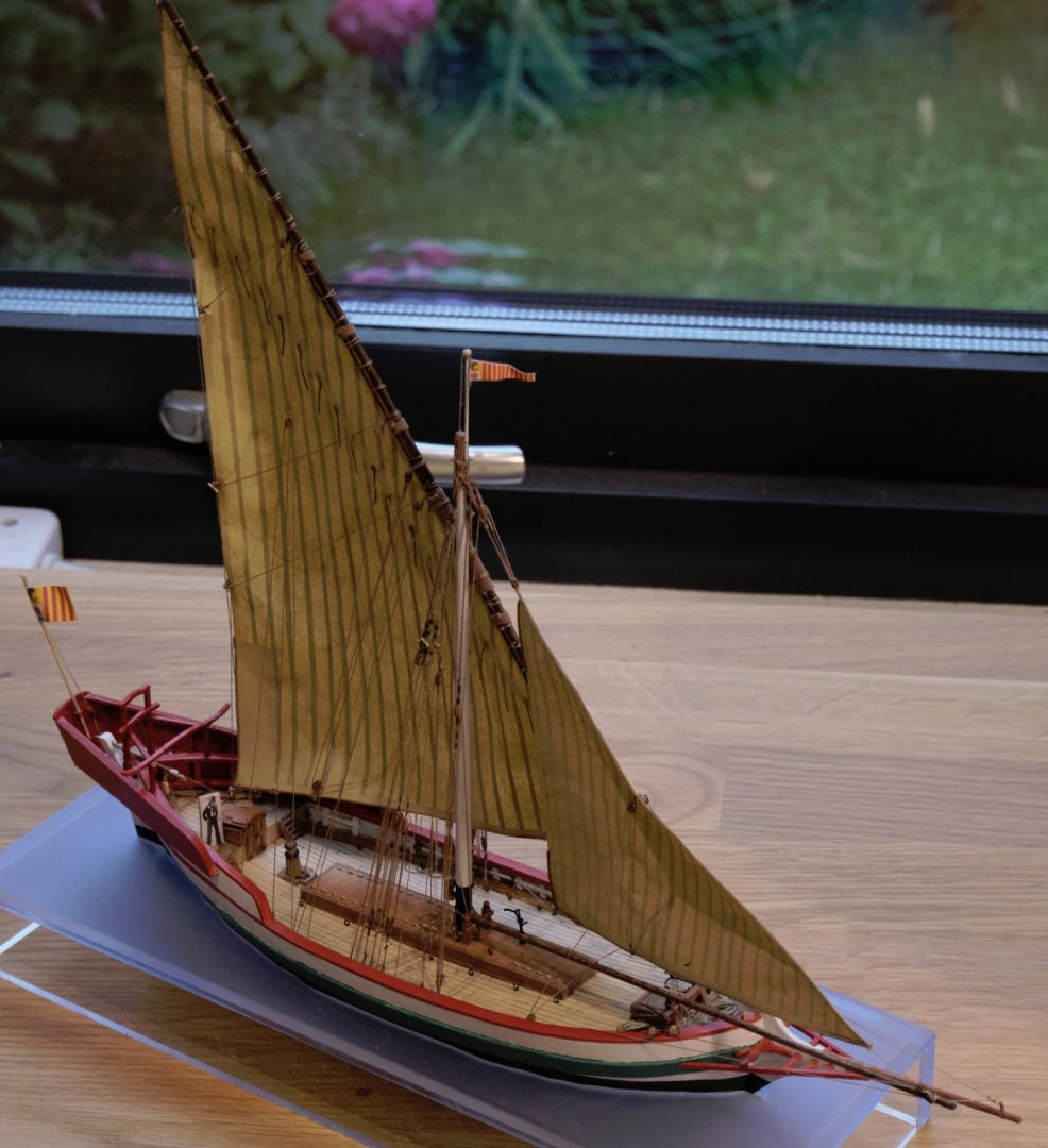
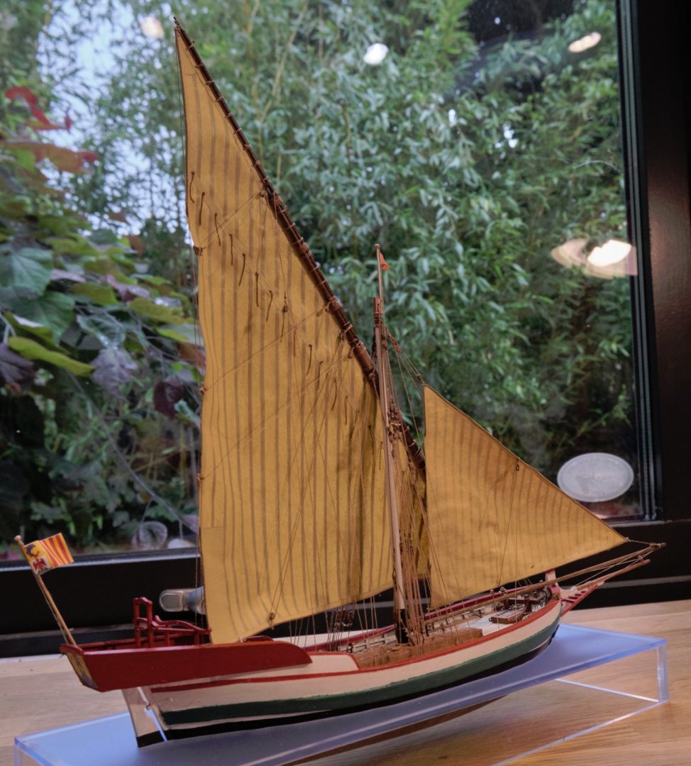
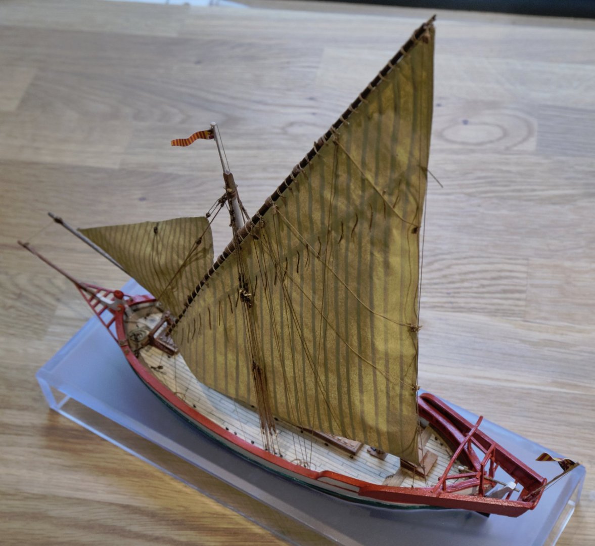
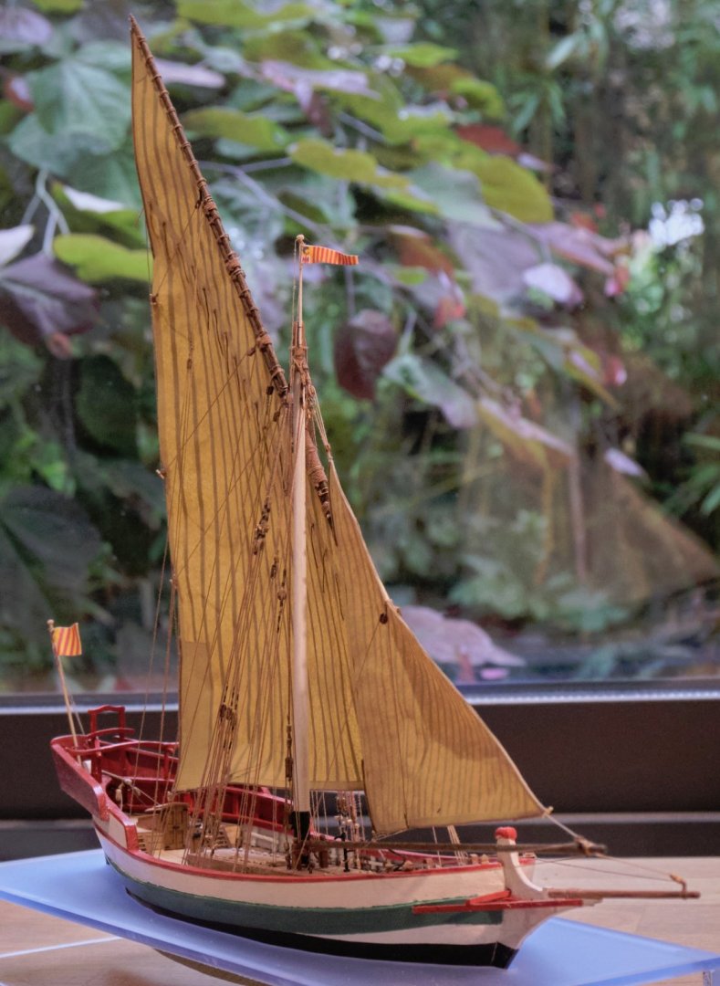
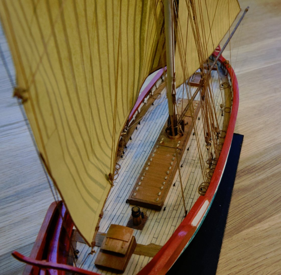
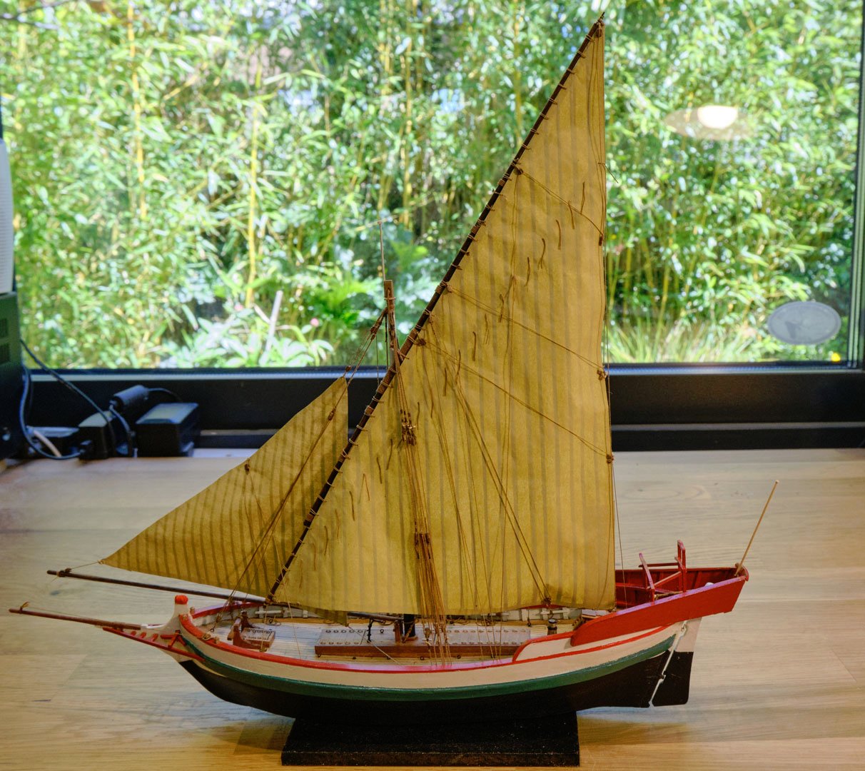
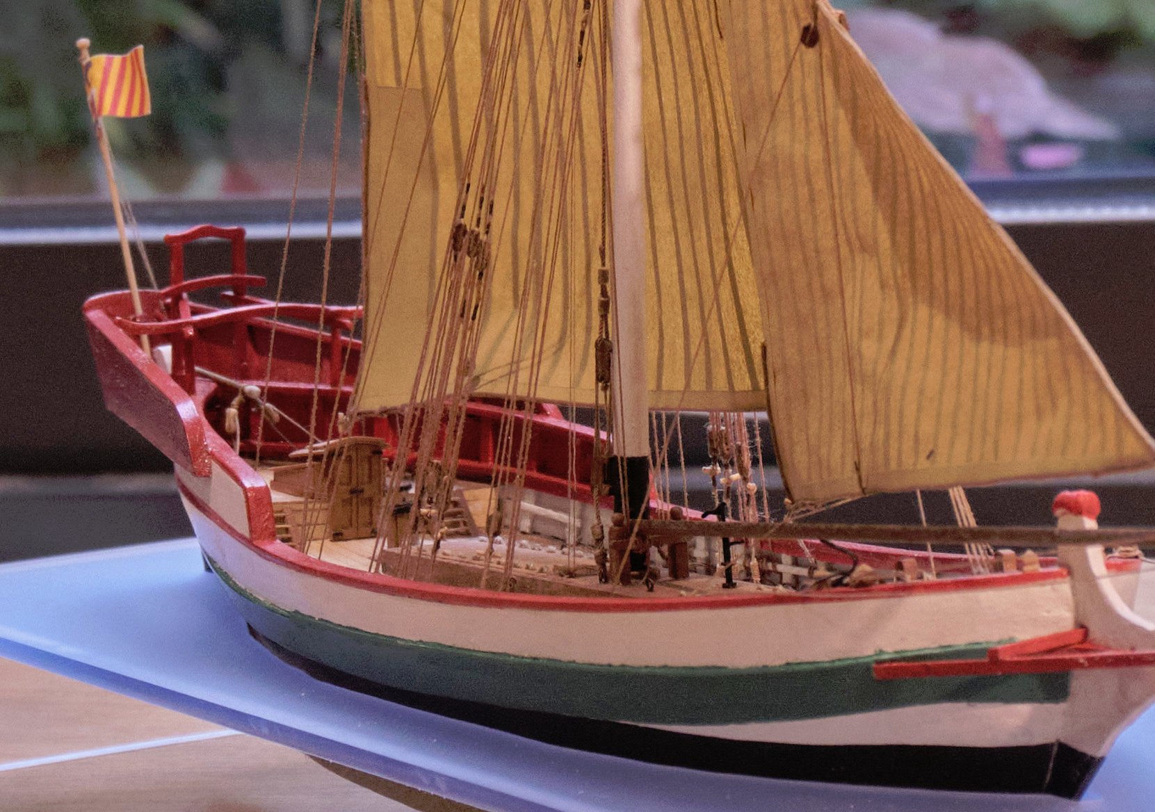
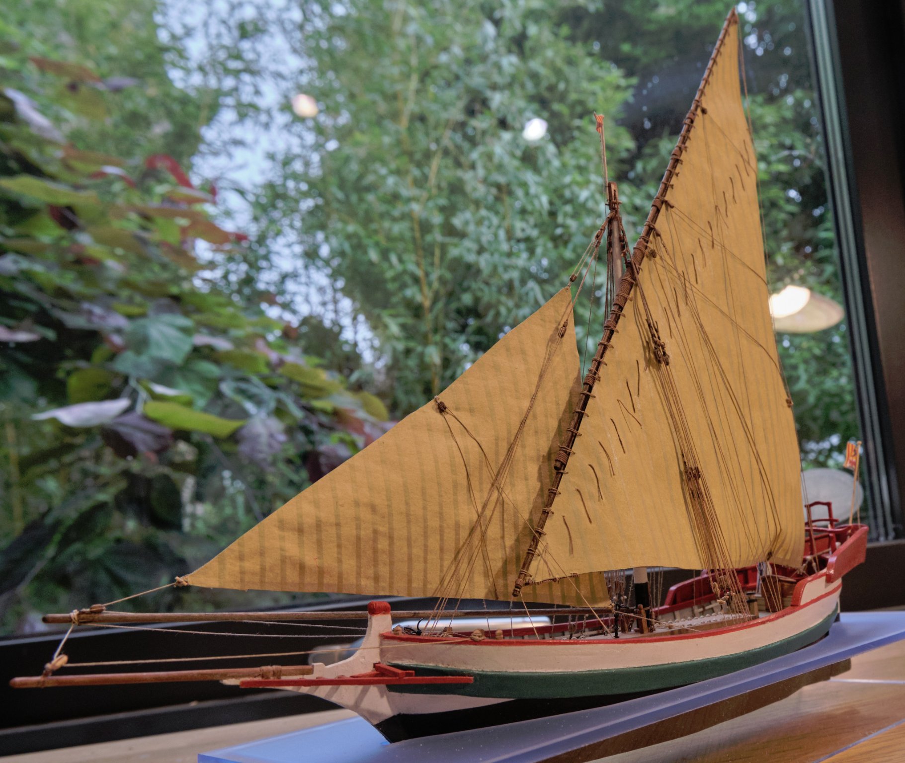
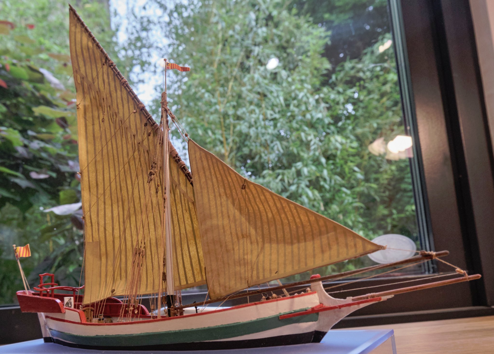
You're welcome to have a look at the overall pictures that follow. If you need detail, they'll enlarge considerably.
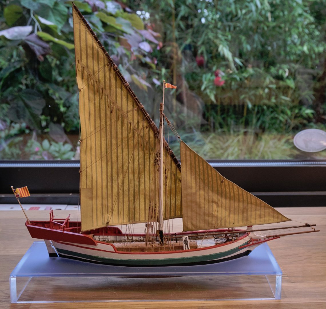
Portfromfrontabove.thumb.jpg.f02f6c91d5c64a078f8bd685f8c5ebf5.jpg)


That's it until next time! I wonder what it will be?
Tony
- egkb, G. Delacroix, bruce d and 9 others
-
12
-
Fittings
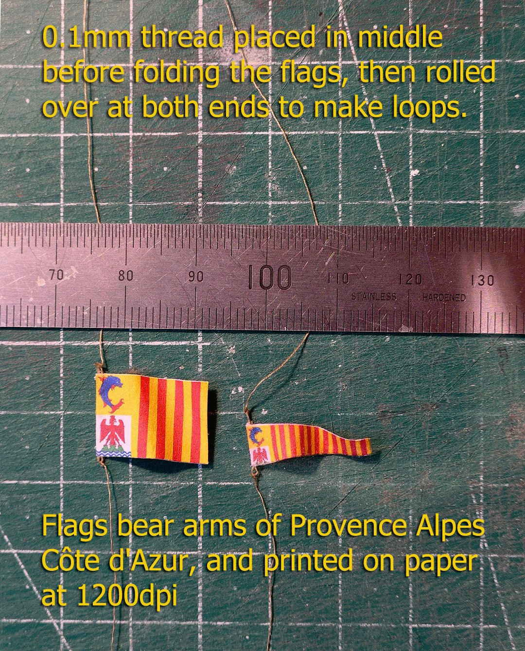
Flags
I eventually gave up trying to make the flags from Modelspan or thin cotton cloth, and instead opted to print them on to ordinary copy paper at a resolution of 2000dpi. At least the definition was ok.
The method was to print the two sides of the flag edge to edge with a 0.2mm gap. I then laid a 0.1mm line down the middle of the inside and folded each end of the line over to form a loop. The two sides were then glued together using a stick glue.
Again the monograph does not reveal the origin of the arms on the flags, but a search revealed them to be of the Provence Alpes Côte d'Azur.
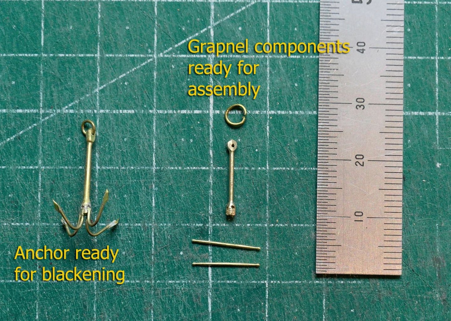
Anchor & Grapnel
I had to make the anchor 3 times before I got the hang of the sequence necessary. The monograph suggests drilling a hole for the arms, but that would still leave the problem of how to solder the remaining two arms at 900 when using solder that has only one melting point.
I eventually hit on the following sequence:
1. Cut a 4mm brass rod to the maximum diameter (1.63mm) of the shaft (i.e. the diameter of the head and crown.
2. Drill a 0.7mm hole for the ring
3. Drill two 0.5mm holes at right angles to each other for the arms near the crown.
4. Mill 0.5mm grooves for the arms from each of the holes.
5. Cut the arm between the holes to the final diameter (0.9mm).
6. Insert the first bar of two arms through the first hole at the crown, then bend them together until they sit in the grooves. Solder with silver solder.
7. Re-drill the hole in the second hole so that it passes through the paired arm in the first.
8. Insert the second paired arm through the second hole, and repeat the process for the first paired arms.
9. Bend all the arms to right angles at the same spot. This makes it easier to solder on the flukes exactly.
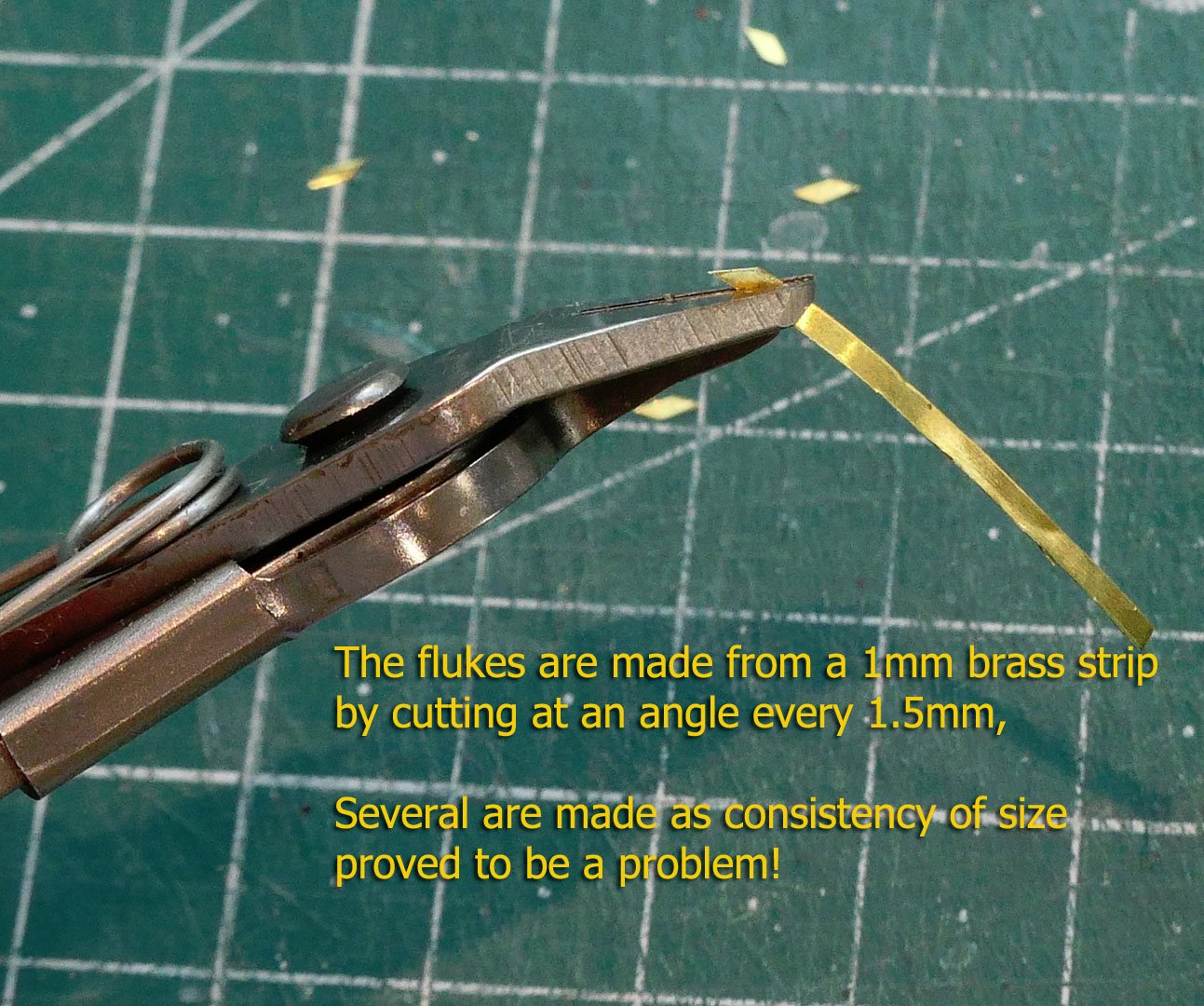
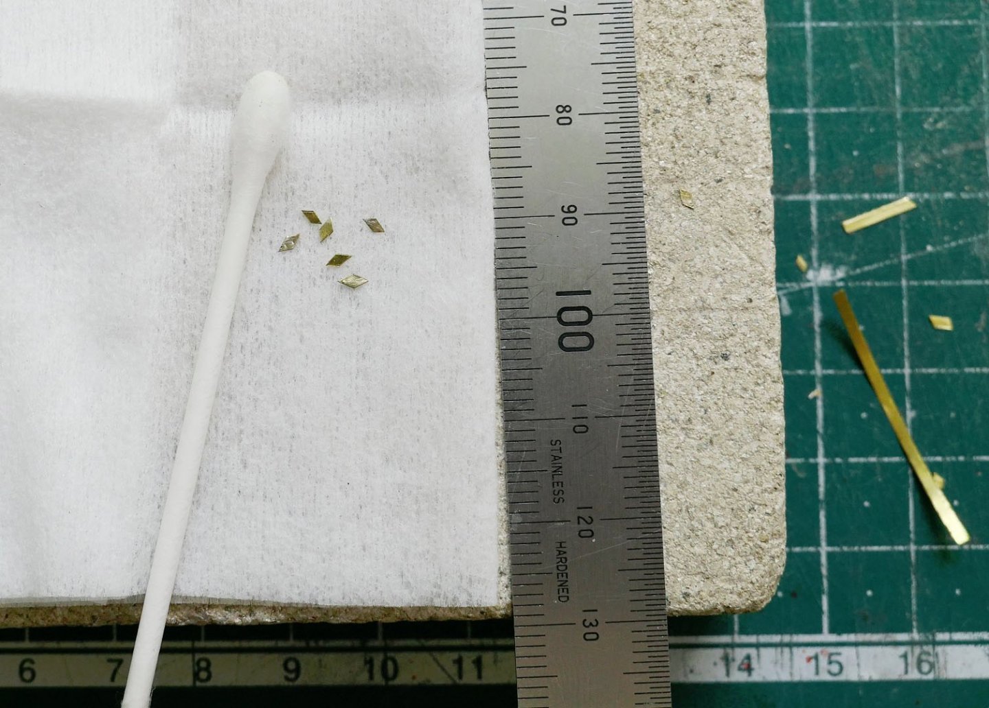
10. Prepare the flukes by cutting a 1mm strip of 0.07mm brass at a sharp angle at 1.5mm intervals.
11. Wipe the flukes with a cloth impregnated with isopropanol then solder to each of the arms.
12. Bend the arms to their final shape.
13. Blacken with Sodium Metabisulphate solution (5%)
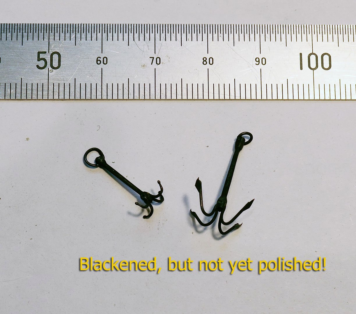
I now just have to put their ropes on, make the stand, and those will be shown in the next post.
Tony
-
I'm sorry I missed this model until now. How wonderful. I love the techniques you use with the simplest of tools. Your work is a real inspiration to me for my next build.
Tony
- Keith Black and mtaylor
-
2
-
Very nice ideas, wefalck. Thanks. I hadn't known that decals could dissolve in that way. Lots to experiment with!
Tony
-
@wefalck: Thanks for the tip, I'll look into it. Decals might attach to painted aluminium. They might even glue to fine cotton voile or silk pongee. There are two problems in addition to lightfastness: (1) the detail of the printout from the inkjet at this scale, especially when the material tends to diffuse the ink, and then (2) material that is thin enough for some realism. I'll also review the ppi of the images I have. I had set them to 600ppi, but that may need to increase.
@Edwardkenway: Thanks for the kind words. I'm appreciating work at this scale as it makes some things simpler and certainly allows for our small storage space. Of course it also makes some things more difficult in terms of achieving correct sizing of parts.
- Edwardkenway and mtaylor
-
2
-
Just thought I'd add a photo to demonstrate scale. Sorry for the slightly dull look to the photos in the last post, I had my screen brightness too low when preparing them.
Tony
- Edwardkenway, egkb, Roger Pellett and 9 others
-
12
-
Rigging completed
I’ve now completed the main rigging. The photos mostly speak for themselves, but I’ll start with some of the detailed ones, and follow with the general views of the model so far.
Lateen halliard
This is not very clearly shown in the monograph, so is worth a look in its final position. The fall is attached to the bitts in front of the mast.

Lateen sheet
The sheets and tacks on both sails are attached using wooden toggles, as was shown for the other parts of the rigging. Note the doubled bolt rope and its lashing to the foot of the sail.
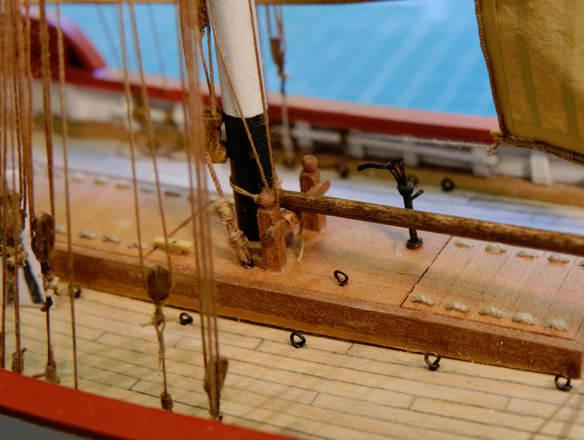
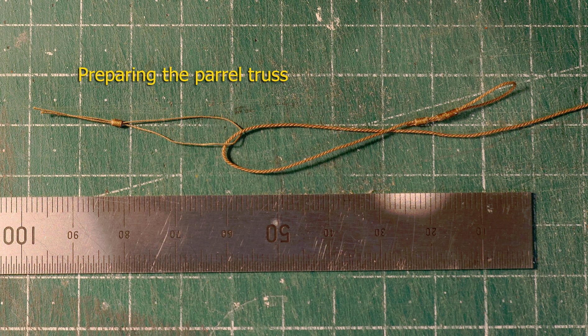
Parrel truss
Here you can see how the parrel truss ended up, complete with its small wooden heart.
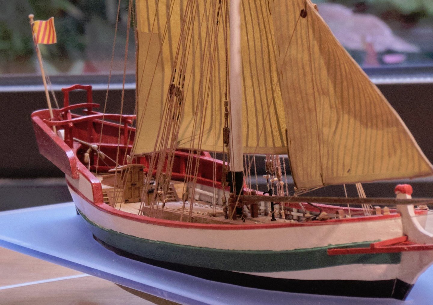
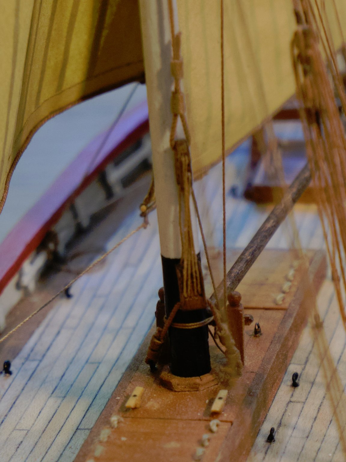
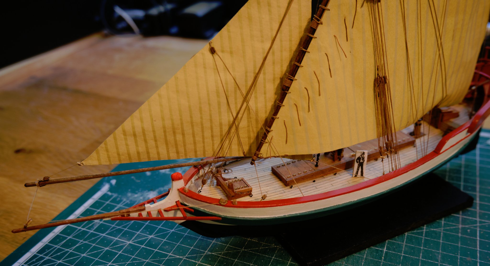
Stemhead
This stemhead (the capioun in French) seems to me to be unique to the Mediterranean lateen-rigged boats. It doesn’t appear in every such boat, but is certainly common. It looks like a roll of spun yarn. I made mine with white epoxy putty.
In the monograph it is shown only in plain wood (the hull is unpainted in the monograph) so I took a guess at the colour and gave it the same red as on the rails. The photo shows it with its first coat, so is much lighter than the colour of the rails. This will be put right with further coats.
.thumb.jpg.37f9e598171e25f375df308ca2f9b43a.jpg)
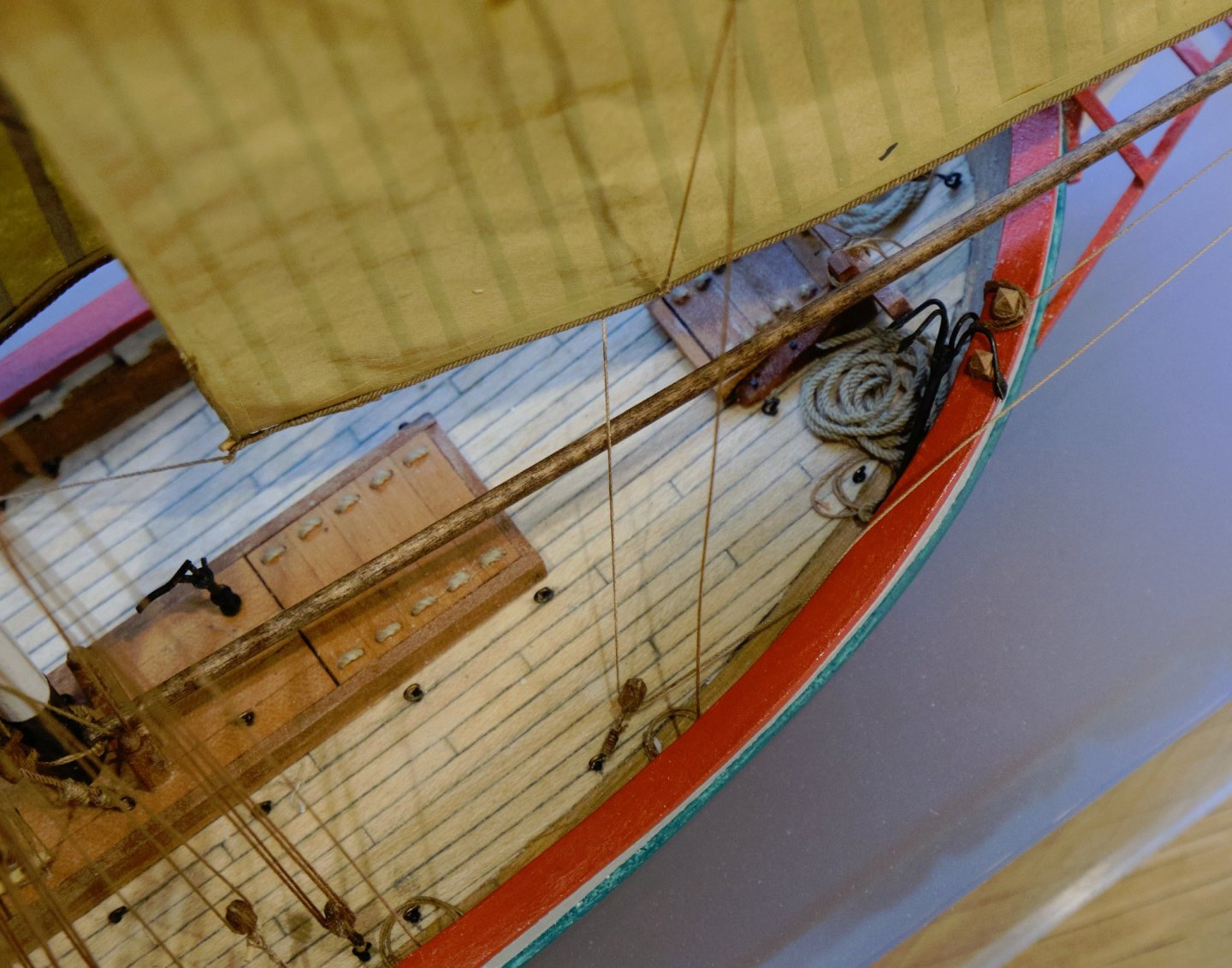
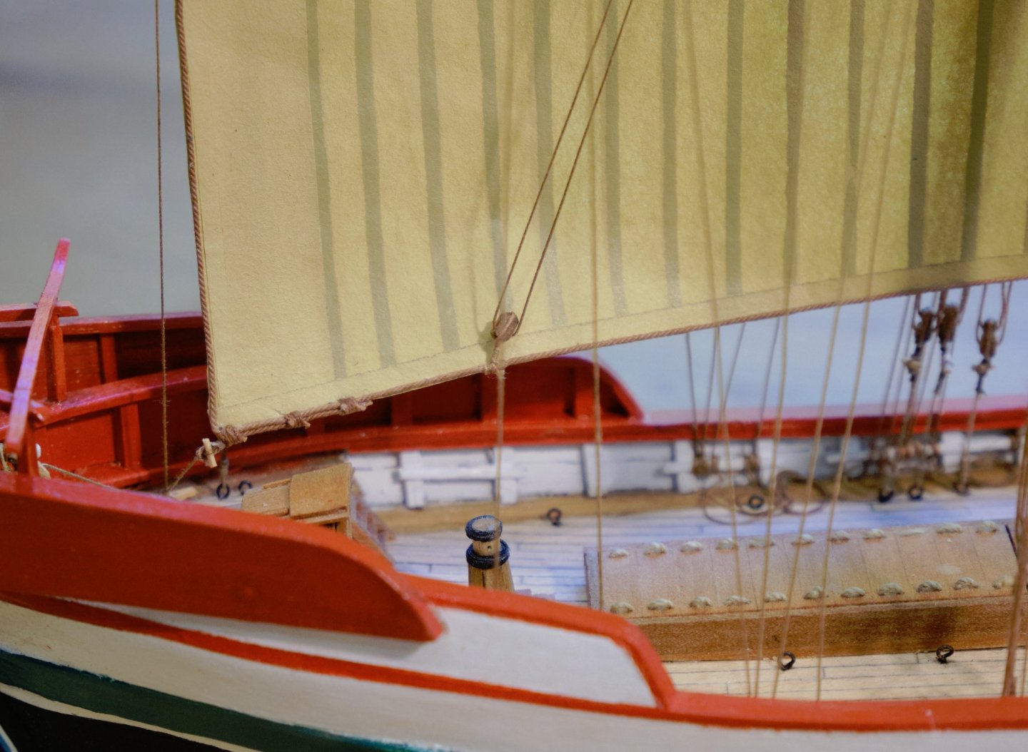
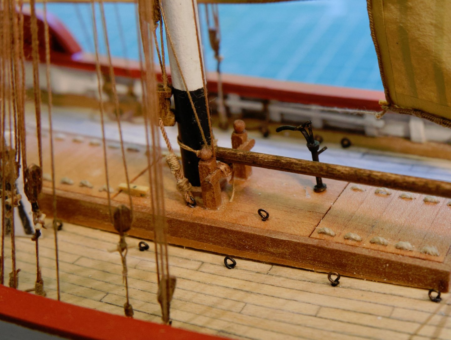
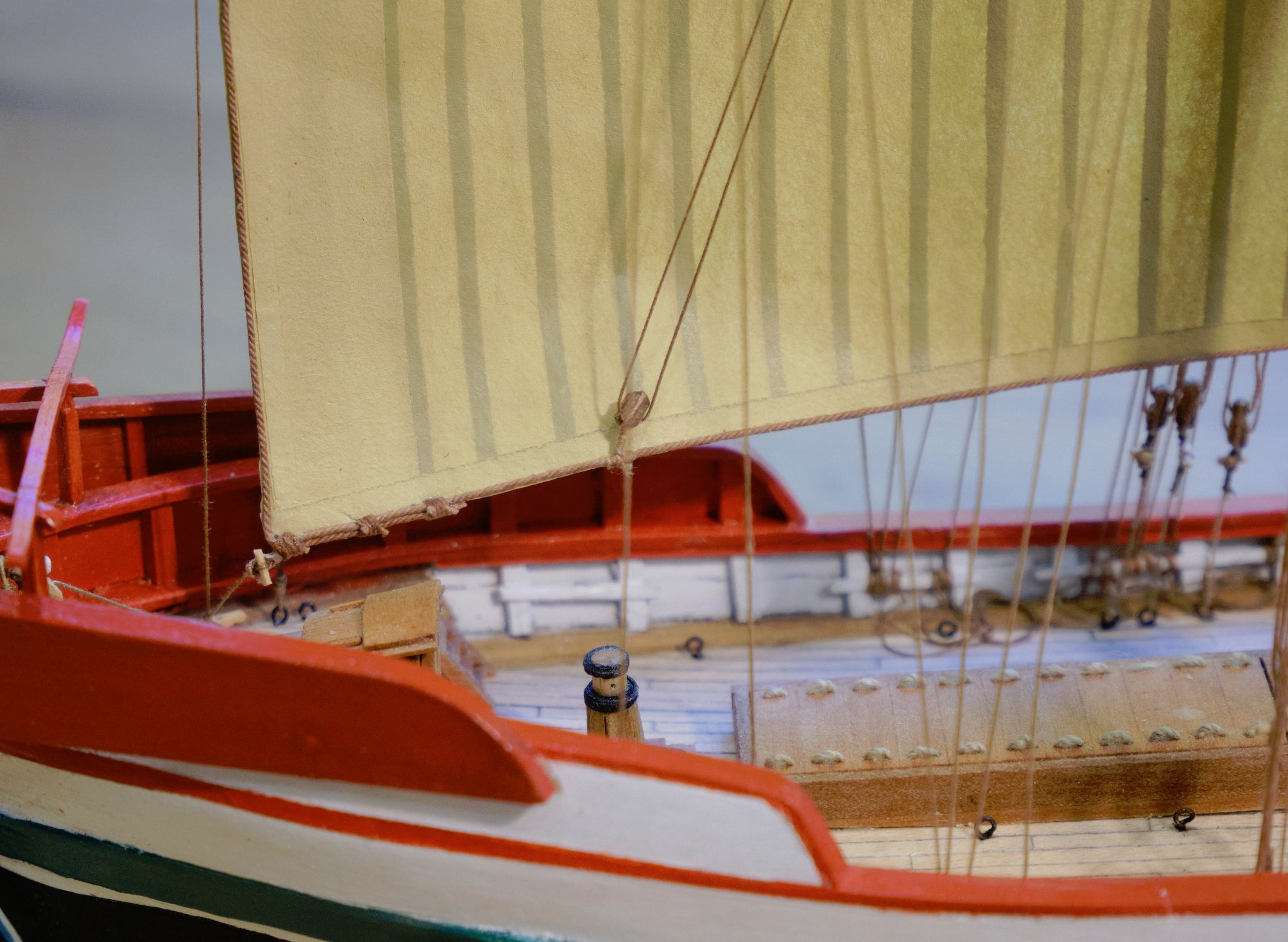
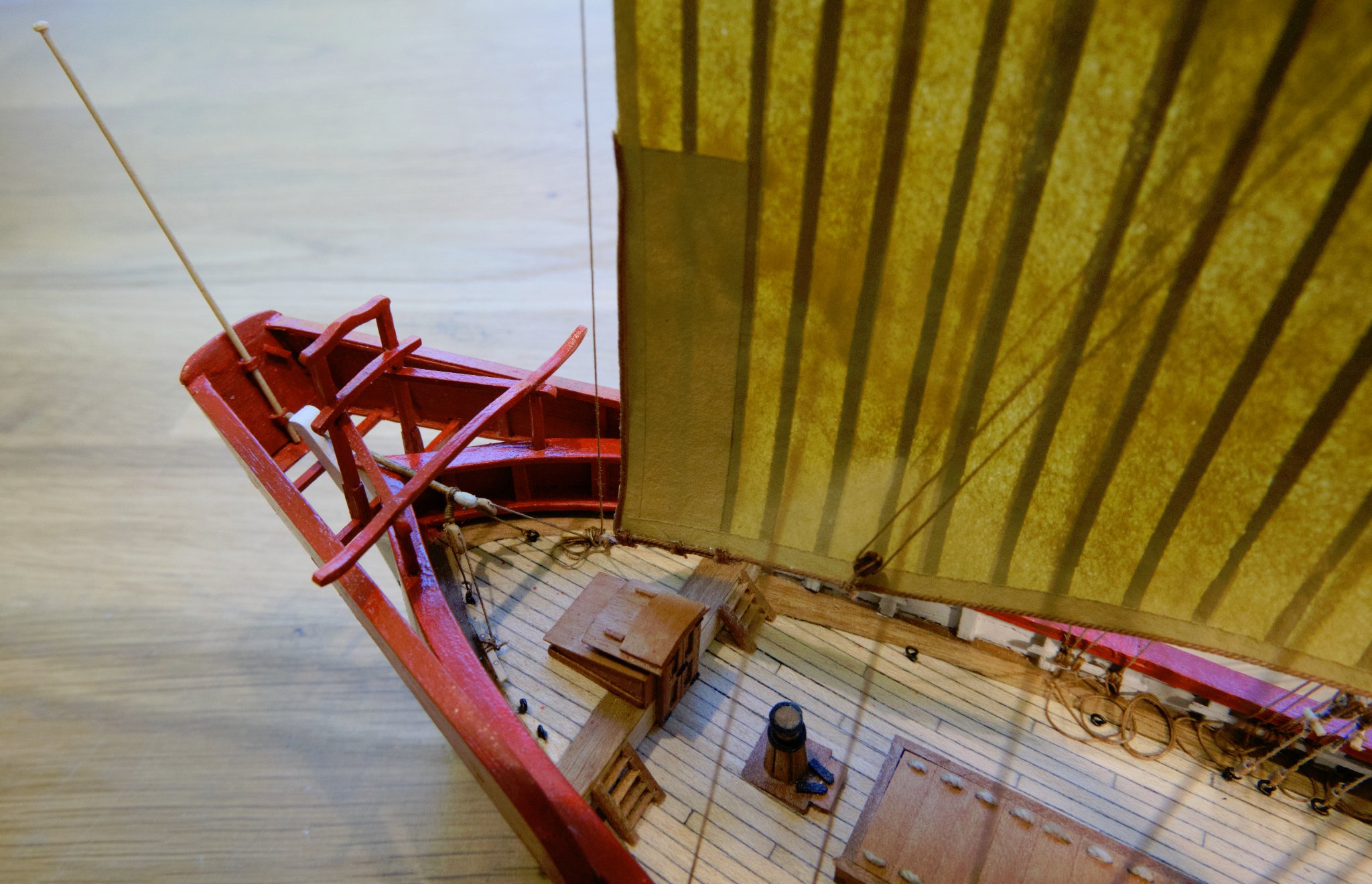
Fore deck bitts
This is just to show the view of the jib boom and the ropes on the bitts.
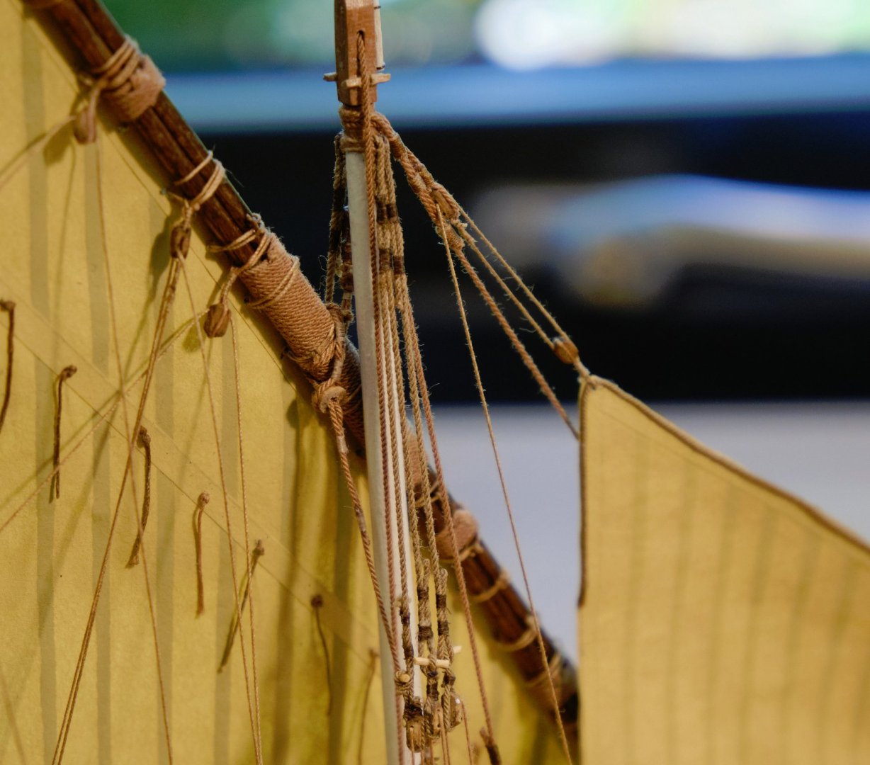
Mast top
This shows the port view of the top, with its parrel truss.
.thumb.jpg.3533f7d6d16a05968a02ab8b20fd5f82.jpg)
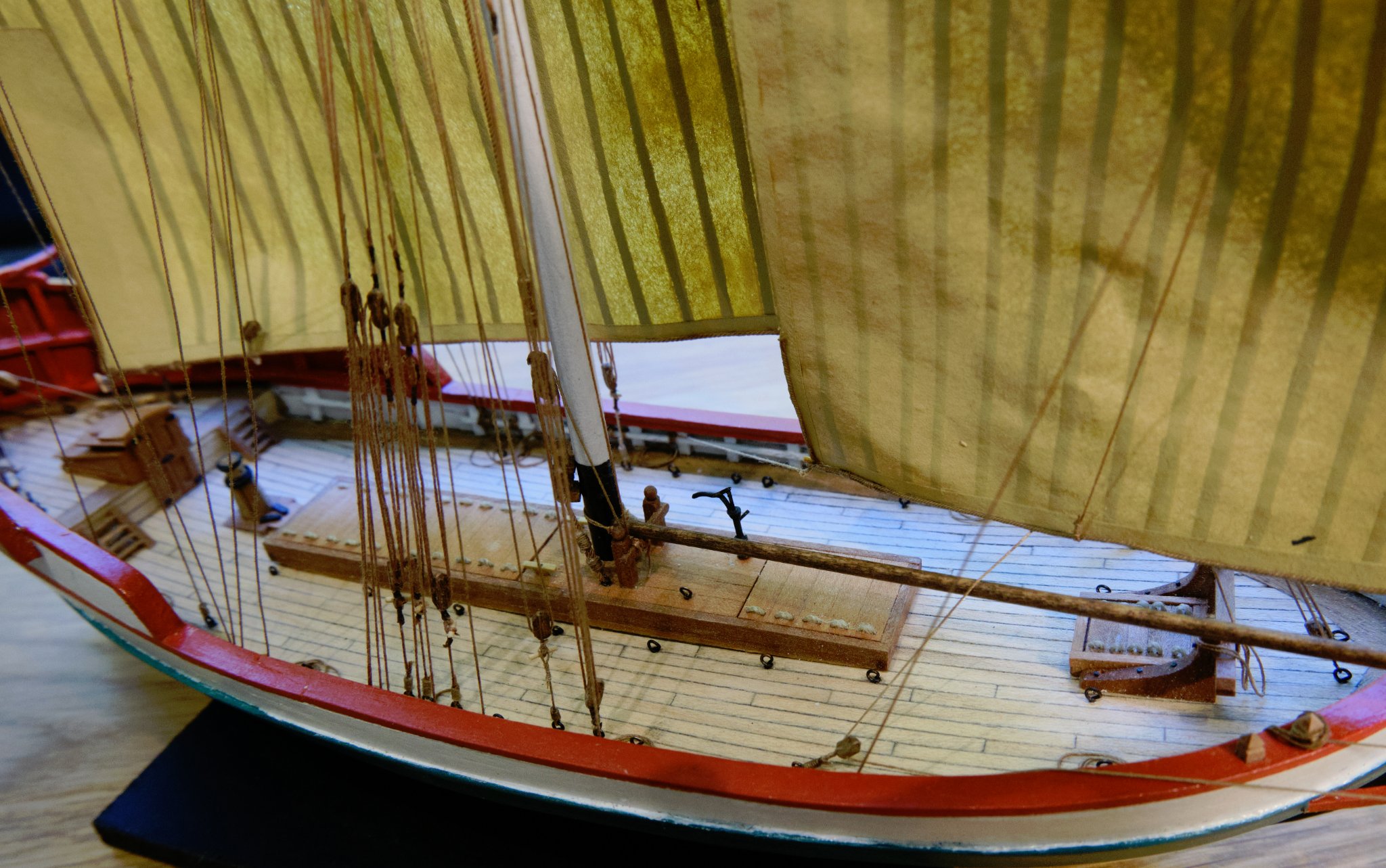
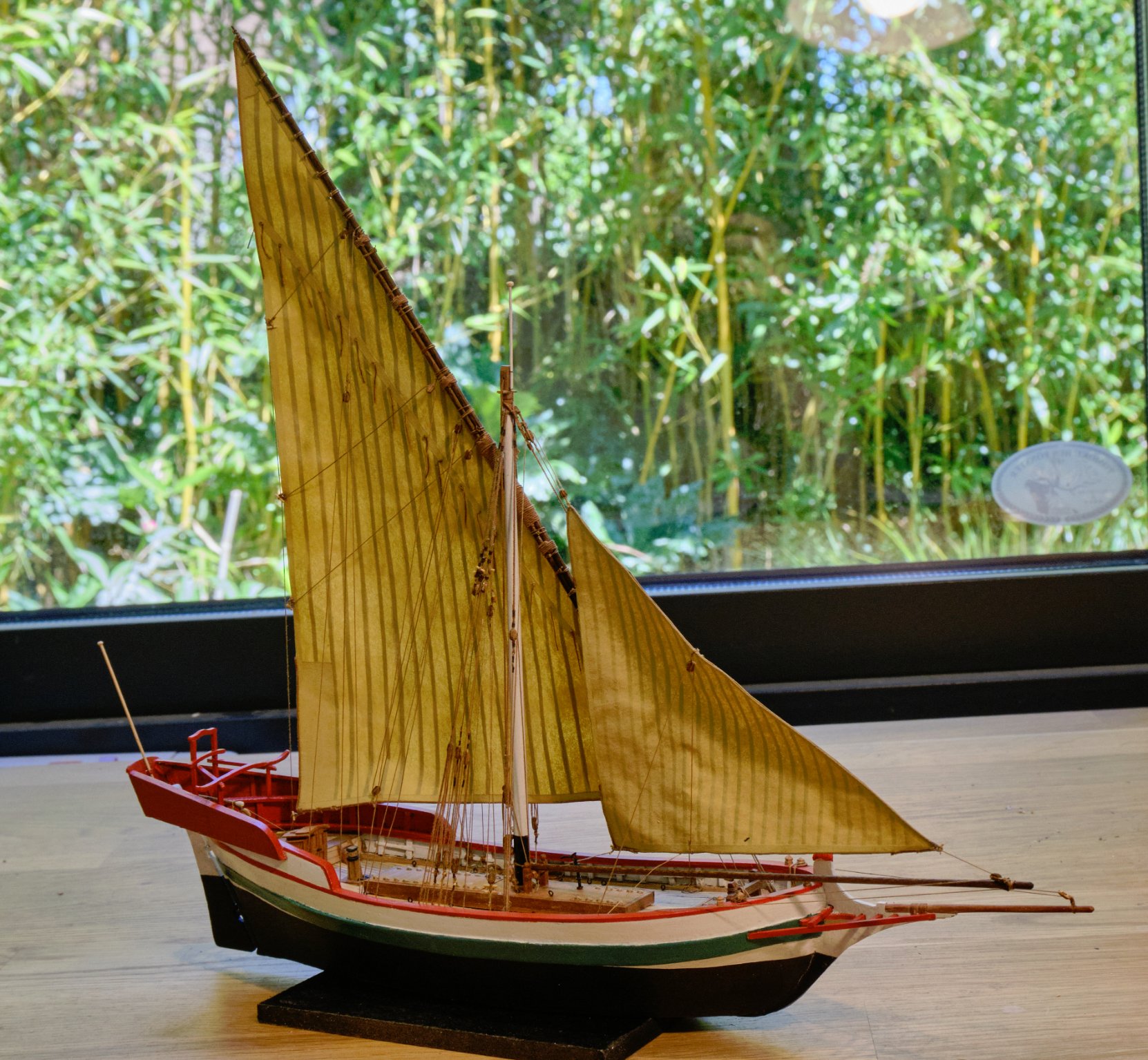
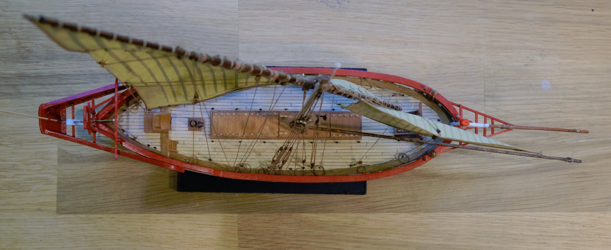
General views

.thumb.jpg.2ab9ce3a7b935deb2825b01a04d795c7.jpg)


.thumb.jpg.f69564899f4744ac1ed411d06f75d794.jpg)


That's it so far. I'm now working on a more sturdy perspex base, and will try other methods of making the sails.
Tony
-
Continued Rigging
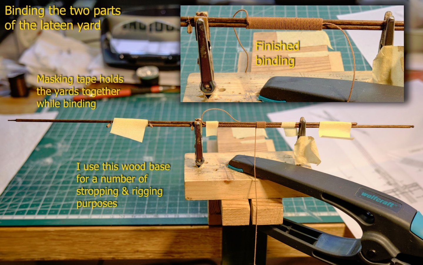
This is not a full description of production of all of the rigging. I’ve left out lots of detail and numerous ropes, blocks and fitting. The following just gives a few of the main points to show some of the significant aspects of the lateen rig.The main visible point is the lateen yard itself. This is made of two overlapping yards lashed together. The picture (and insert) shows the use of 0.5mm rope to do this.
A slightly tricky operation was making the halliard and parrel trusses. The diagram in the monograph shows them as follows. Note that the halliard truss requires a circular rope which is tied to form a loop at one end to accept the toggle holding it to the halliard. I just spliced the ends of a rope together and then formed the loop with fishing line. I don’t have a picture of that, but I do have one for the parrel truss (unfortunately without the small wooden heart I made from 2mm dowel).
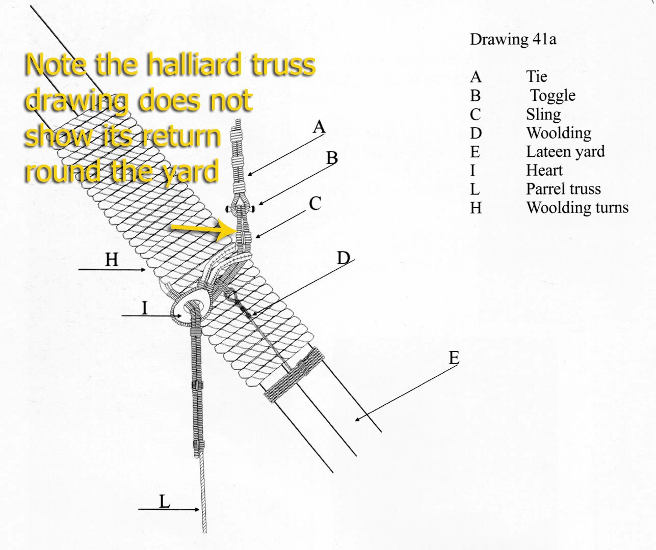

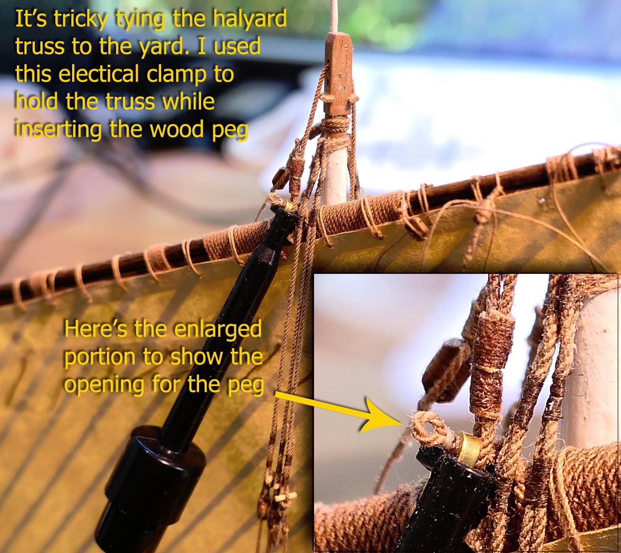
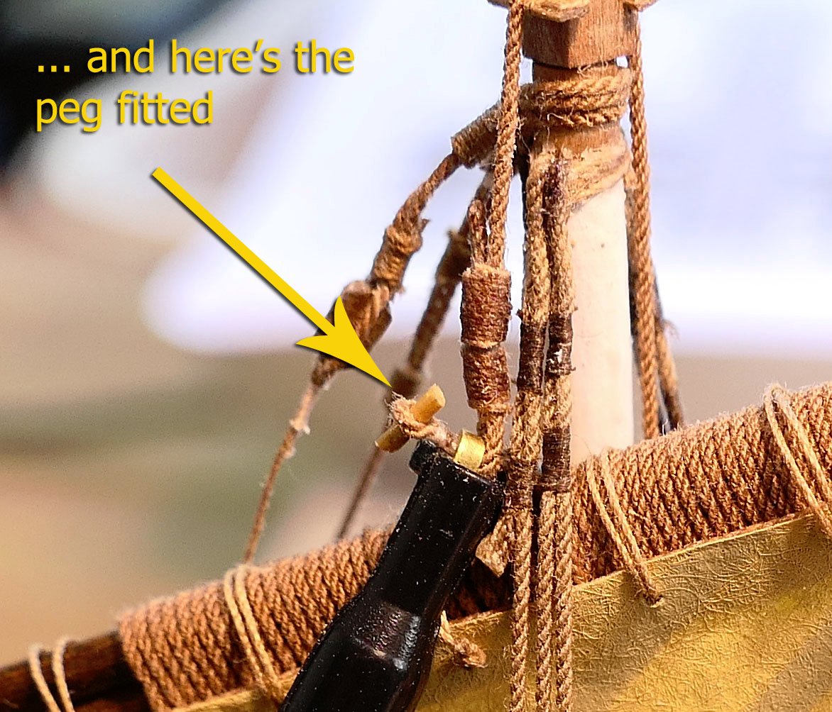
Fitting the yard by its halliard truss was also tricky. I managed this with the use of an electrical clamp. This held the truss with its end open (as shown in the insert) so that the peg could then be placed in it.
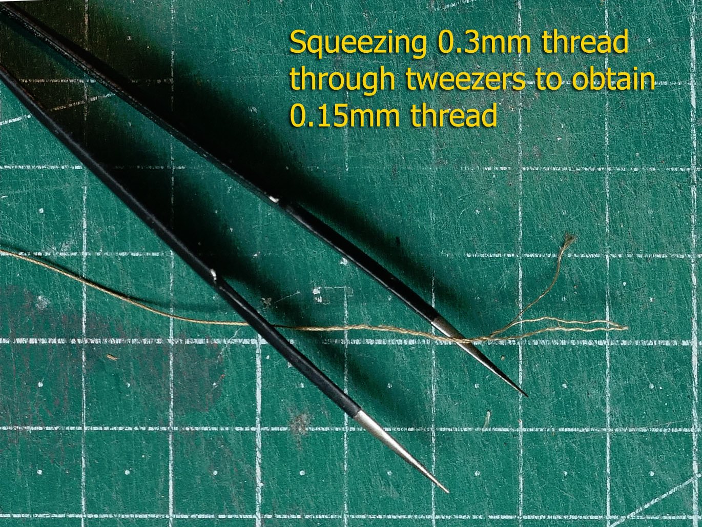
I found after a while that the use of fishing line, although wonderfully fine, was very tricky to use without its disintegration and with the need to seal it with CA glue. Eventually I decided to unravel the 0.3mm DMC Cordonnet 100 thread which I like very much for its strength. I used a pair of fine tweezers to do this. It was far simpler and quicker than I thought it would be. (I also tried this on ordinary cotton sewing thread, but this was a failure as it just disintegrated).
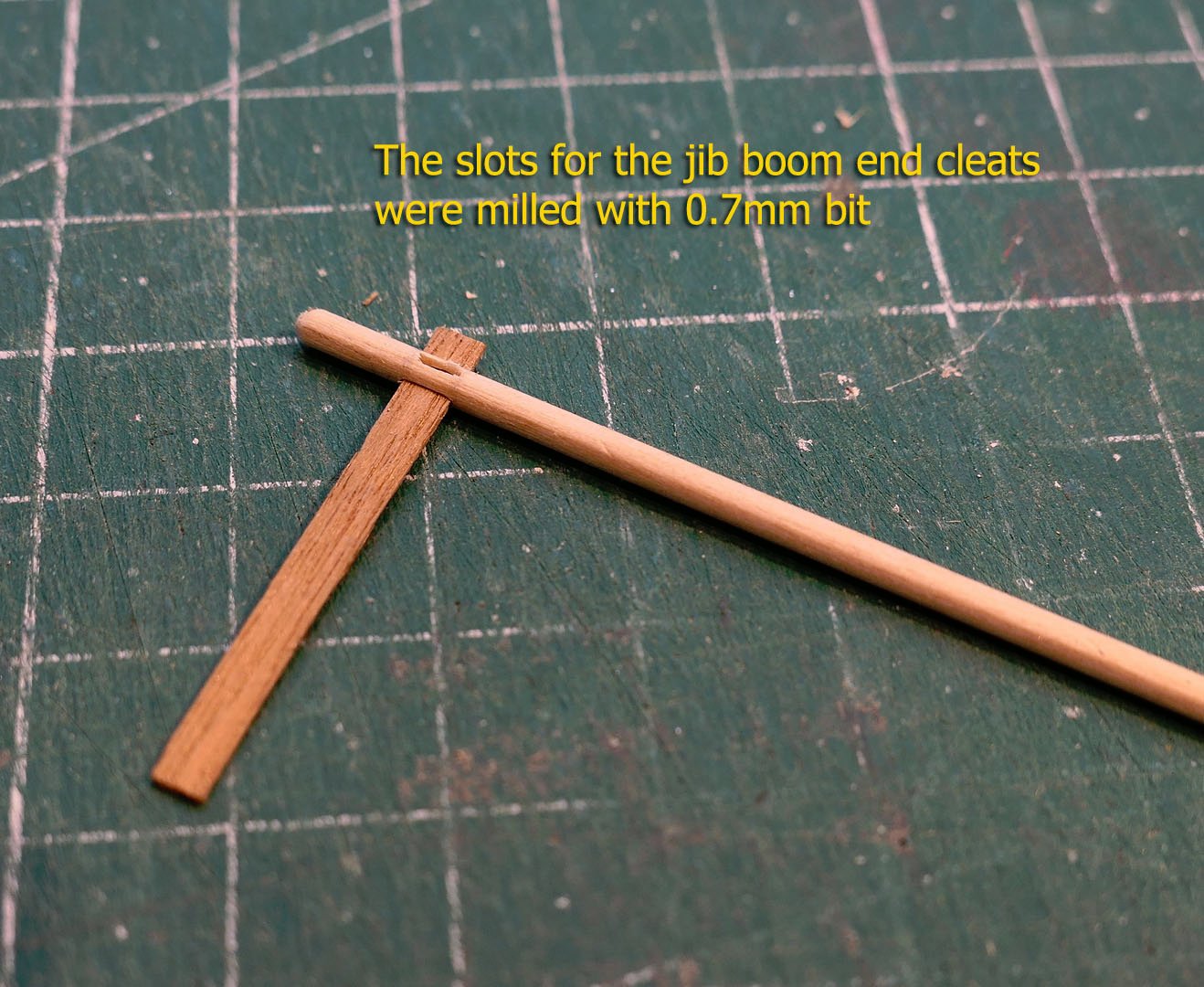
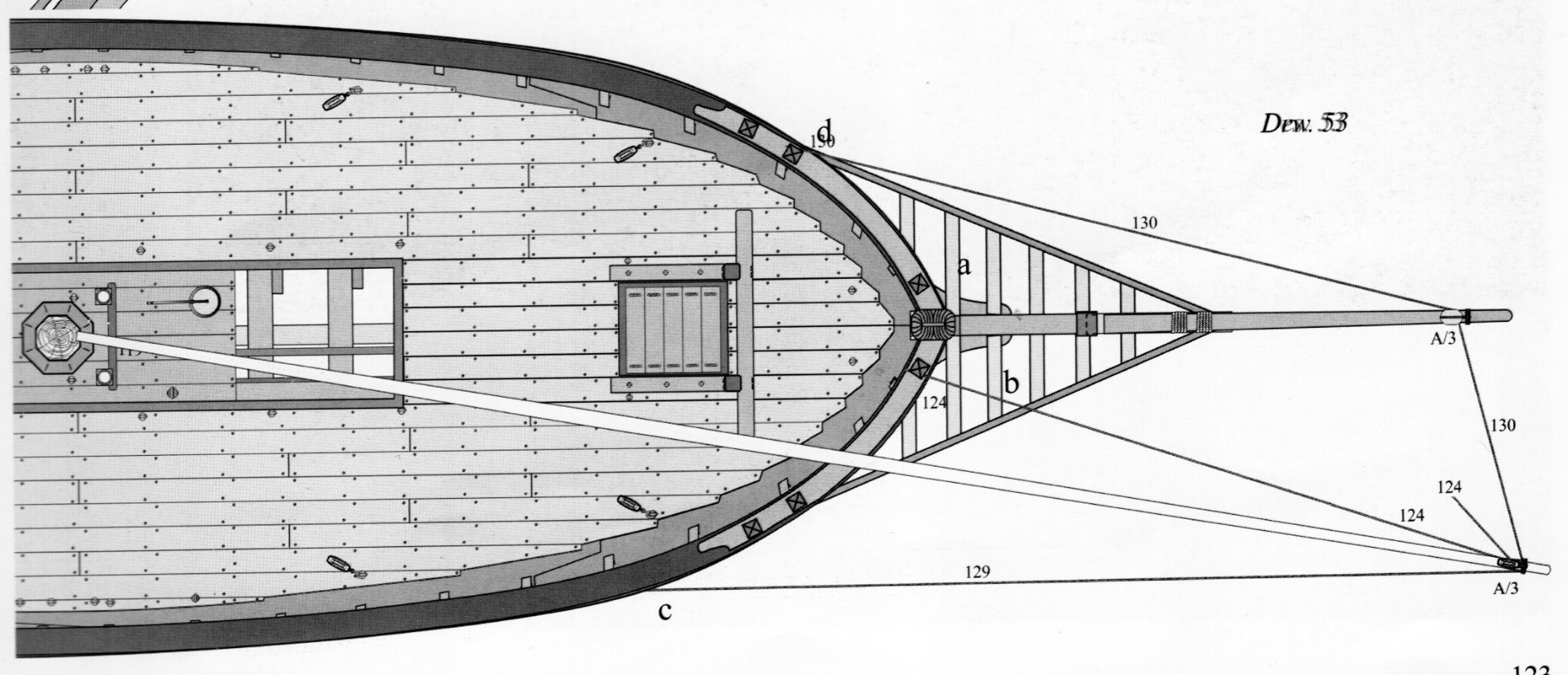
The jib boom
There are two ways of fixing the jib. The simplest is to tie the tack directly to the block at the end of the bowsprit. The other is to use a jib boom. The monograph shows this as follows.
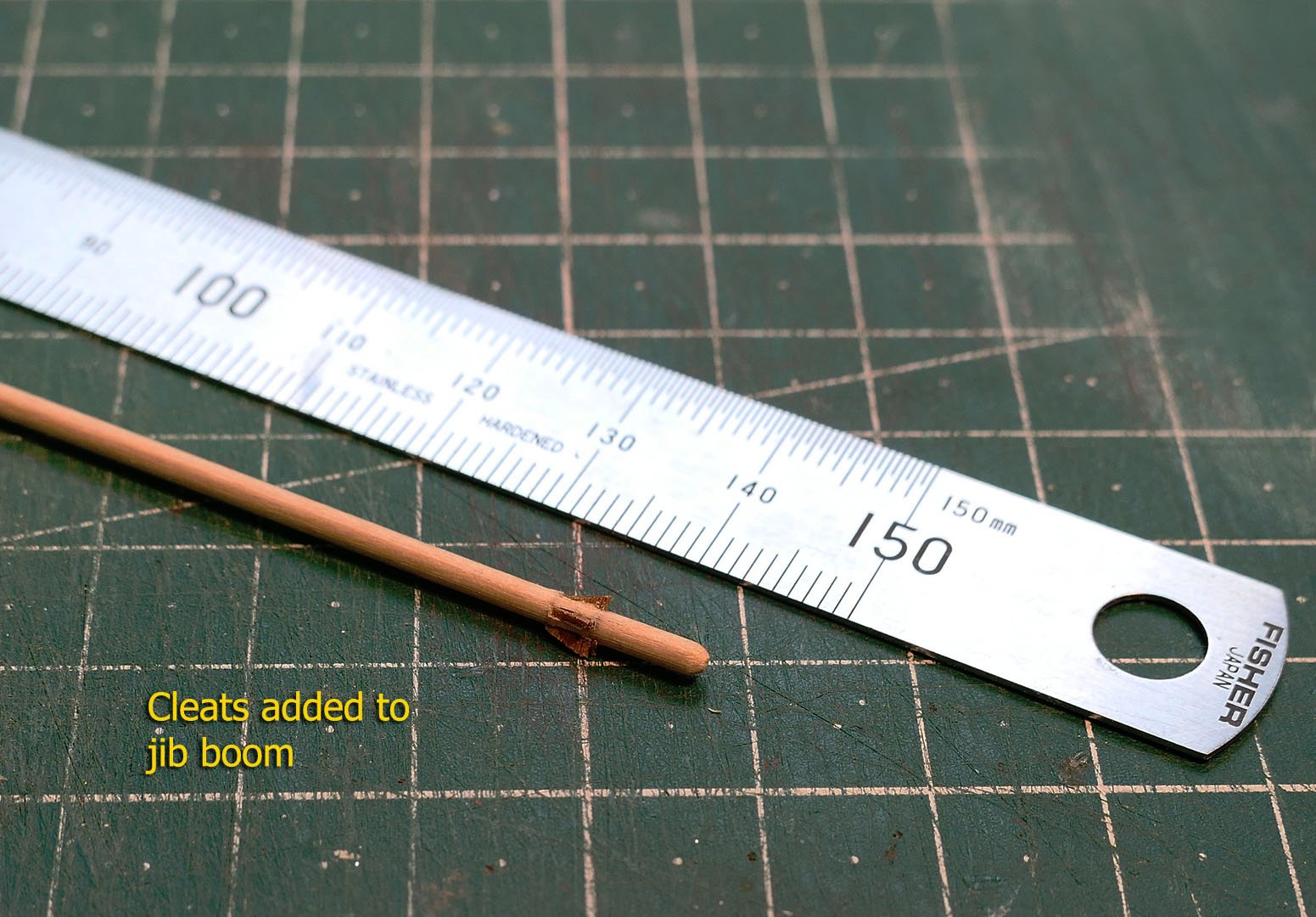
The first step was to mill the holes for the cleats at the end of the boom.
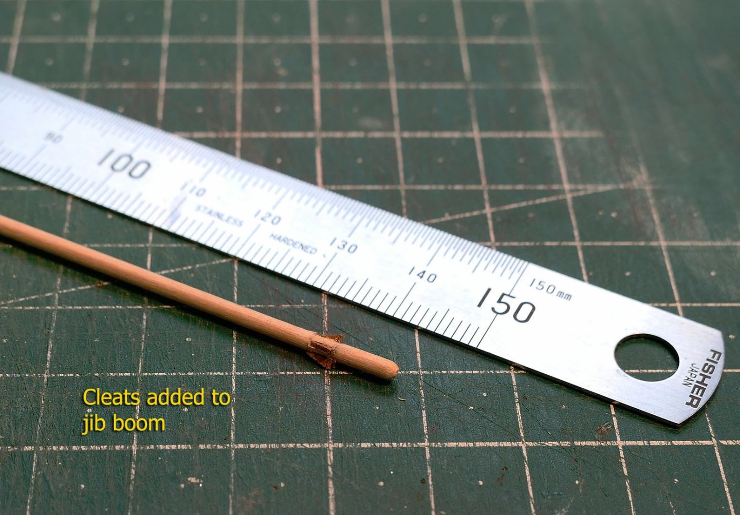
The cleats were then glued and shaped as follows.
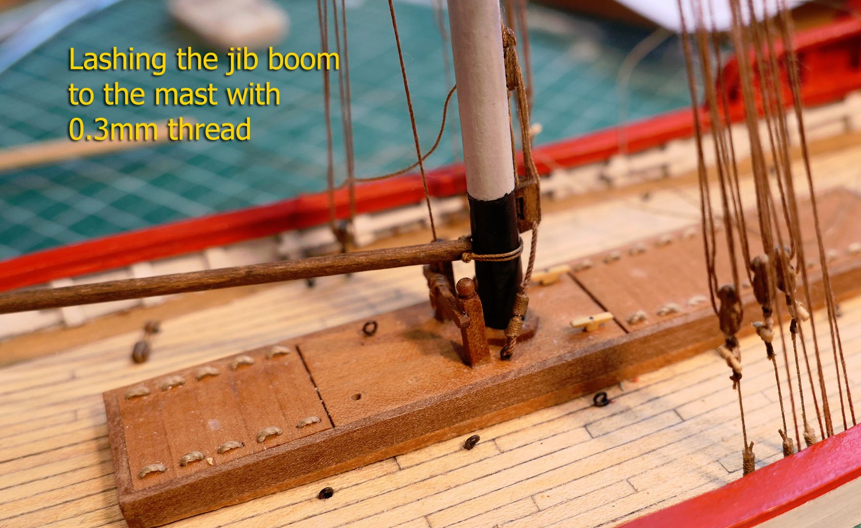
The boom was then lashed to the mast. The monograph does not show this at all clearly, but using the photos from Fissore’s site I was able to see it was a simple lashing with a double turn of the rope.

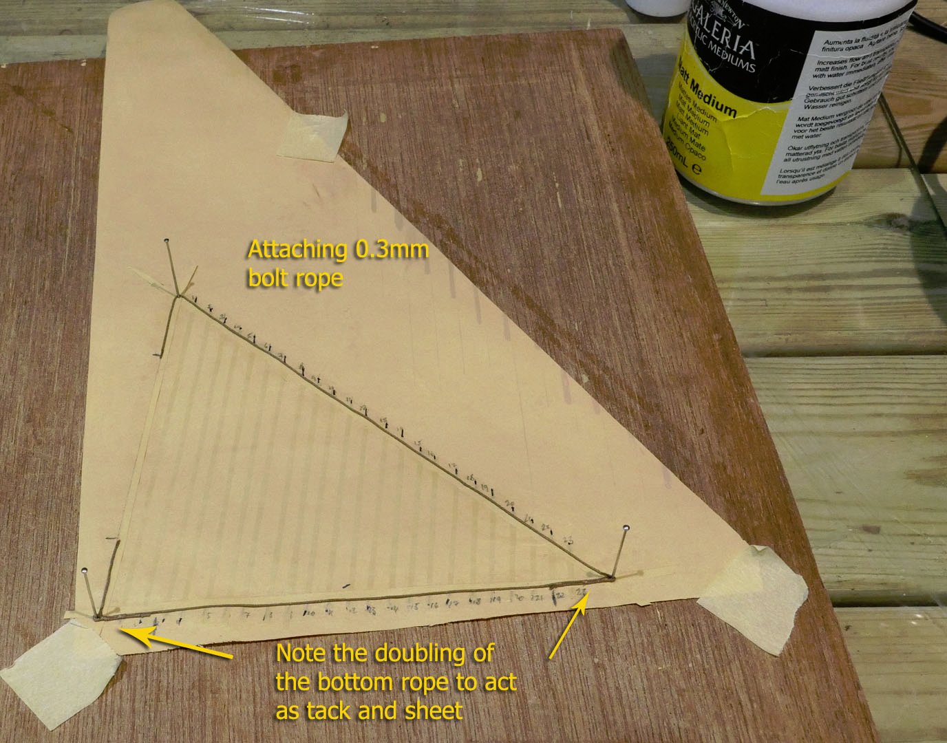
Sails
I made the sails in the usual way with ModeSpan, coloured with a mix of Titanium White, Unbleached Titanium and Yellow Oxide.The seams were done using the same mix using a drawing pen, but with a touch more Unbleached Titanium.
The seams and bolt rope were fixed using matt medium.
Note the foot rope is doubled over to hold the tack and the sheet.
.thumb.jpg.8c001a754e78302b9f81a89066dda615.jpg)
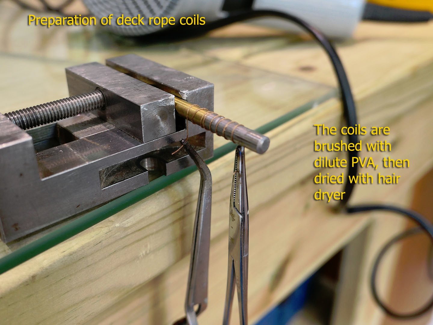
Rope coils
I prepared rope coils for lying on the deck. This was done by winding them loosely round a 5mm drill, then fixing their shape with white PVA. Several coils were thus made in one go and cut into coils of two or three turns.
Flag and pennant
I experimented with the use of ModelSpan to make the flag and pennant. This involved painting the ModelSpan with acrylic varnish on both sides (in an attempt to make it impermeable to printer ink). The paper was then fixed to a sheet of ordinary printing paper and printed with an inkjet printer. The tissue was then removed and covered again with varnish.
My first attempt ended with smearing printer ink over the flags. The second attempt was better, but the result was so transparent that it looked ridiculous.
I then covered the rear surface with white paint to stop the translucency, but that also ended in failure as the white ink still permeated the flag in spots. It also lacked good resolution of detail. So I’ll just have to keep trying.
.thumb.jpg.a1df6daaa09d93dadde449dbe42c6275.jpg)
That’s it for this posting, but I have completed the rigging and I’ll deal with that shortly in the next post.
Tony
-
9 hours ago, allanyed said:
Can't remember other kit builders doing this
Both @Dubz and @Siegfried bought these Sherbourne plans (of which sections were shown) and there was much critical discussion of them, especially from @Stockholm Tar, when I was building mine. For example about the gunport lids, the horse and the windlass. The belaying plan, although obviously not on the original plans, also came in for much discussion, especially round the bowsprit.
Tony
- Edwardkenway, egkb and allanyed
-
3
-
On 5/21/2021 at 11:40 AM, druxey said:
I don't have a suitable tiny milling cutter to do this on my small mill
I am totally out of my depth here, but although the cheap Chinese carbide micro-mills used for cutting PCBs have a reputation for being very brittle and not useful for wood, I have used the 0.4 bits as mills (as well as drills) on pear and boxwood and while I certainly did break some in early experiments, I found that if I go to a depth of about 0.1mm at a time, and travel slowly with my Proxxon MF70 mill, I have no breakages and a clean line. The downside is, of course, that it takes a longer time and patience is needed while watching the bit so that I stop if there's the slightest sign of bending. Unfortunately this still hasn't improved my skills very much!
I apologise for treading where angels would rather not, but I thought I'd throw this in as an example of an amateur's experience.
Tony
-
Well said, George. We all have our own particular motivations. I make models for my own enjoyment, not for others. I enjoy the simple exploration of how to do it and still come out with some kind of a complete model. I also like exploring the different types of look of ships and boats. In any case a true replica would not only involve something at full size, but also detailed photographs of the original, together with detailed explanations of the actual rigging practice and sail plan of each particular captain of the boat in question, together with a choice of the actual time of a particular day that the replica was to be built. Some folks in fact try to do that, but each to their own limits; the level of faithfulness is up to each modeler. I still much enjoyed your Sherbourne, especially as you helped me understand how to interpret plans and instructions. Thanks for the continuing stimulation!
Tony
-
On my plans scarf A and scarf B are exactly the same size. You could trace them to check or use dividers. I note that there is a fold going across the tip of scarf B, so is this where your measurement might be going wrong?
The other thing is that if you have used scans or photocopies to go to 1:24 there may well have been distortions in the scanning process.
Gérard is very precise in his drawings, and when there are errors in Ancre plans the ones I have found are always due to mistakes by the author.
Questions about the Rochefort have been pretty thoroughly examined in the Marine & Modélisme d'Arsenal forum, so you could also have a look there about issues that come up as you build.
Good luck with the answer!
Tony
-
-
-
Sure it can't be straightened out? Under a heavy board for a few days, after wetting perhaps. I don't know as I've never tried such a thing, but there may be a solution. Better to pause before a rebuild, I would think. You've done so beautifully so far.
Tony
- mtaylor, EricWilliamMarshall, G.L. and 2 others
-
5
-
-
Great thought about those cheap collets which can be used as clamps. Thanks a lot!
Tony
- mtaylor and thibaultron
-
2
-
-
-
Whenever I look over at the log of @giampieroricci in his build log of La Venus at a scale of 1:96, I shudder at the thought of presenting my own build of a much simpler vessel at about the same scale. It shows me just how far I have to go in terms of skill and workmanship. However, as I’ve said before, I have to learn before I can do; and this log is definitely aimed at others who like myself are just starting model making, and who may like to follow the detailed steps of my learning.
The main issues for me are the shaping of very small pieces, and, as you will now find out, my need to improve on rope-making and finish at this scale.ROPE
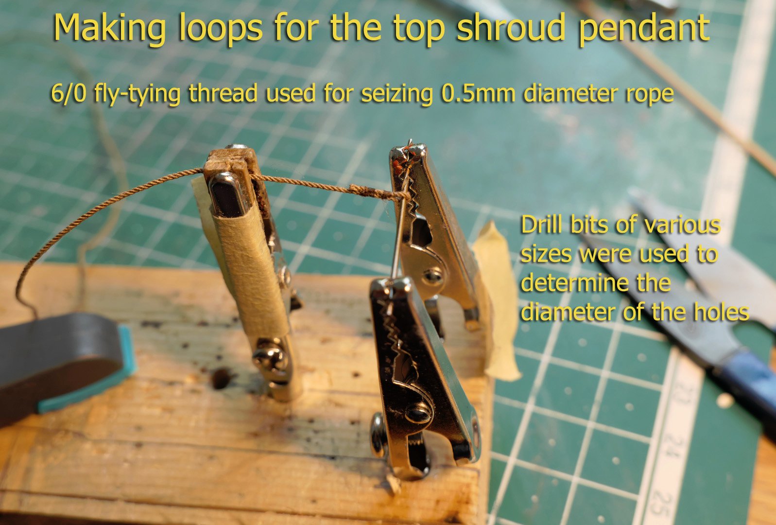
The shrouds, at least, have for most of their construction, a rope diameter of 0.5mm at this scale, making it easy to produce shroud-laid rope with existing threads. However the smaller ropes required rope of 0.2‑0.3mm and so for that I went with ordinary cotton thread for the 0.3 size, and DMC Cordonnet 100 Off‑White thread for the 0.2. For the smaller seizings I used Uni‑Thread 6/0 Waxed Fly Tying Thread. Walnut crystals dissolved in water with a dilution of 1:30 were used to dye the thread.
What I didn’t do, and should have done, was to ensure that the fluff of the cotton thread was removed. I only noticed this too late when photographing the rigging in close-up. I console myself by saying that at standard viewing distance it is not really noticeable, especially when the rest of the build is not exactly perfect. Perhaps I should try polyester threads in future.
SARTIS
I was puzzled by the use of the word ‘sartis’ in the monograph when referring to the shrouds, as may some others when reading the monograph. So, just in case anyone is interested, I did a bit of research. The word derives from the Italian ‘sarte’ or ‘sartia’ which means ‘shrouds’, from the verb sartiare, meaning ‘to rig’. As the monograph is a French translation of the original Italian, this is not surprising.
However according to the Glossaire Nautique Répertoire Polyglotte De Termes De Marine Anciens Et Modernes, by A Jal (1868), it was also a word used in a number of ways to define the rigging of a lateen sail in 19th century France, mostly in Provence. This could refer just to the pendants hanging from the calcet, the pulleys at the base of the pendant, the falls of the pulleys, the strops at the base of the shrouds, or the entire length of the shrouds. The particular usage that applies here is not clear in the monograph, as on the diagrams it is used variously, I’ll just refer to the shrouds.SHROUDS
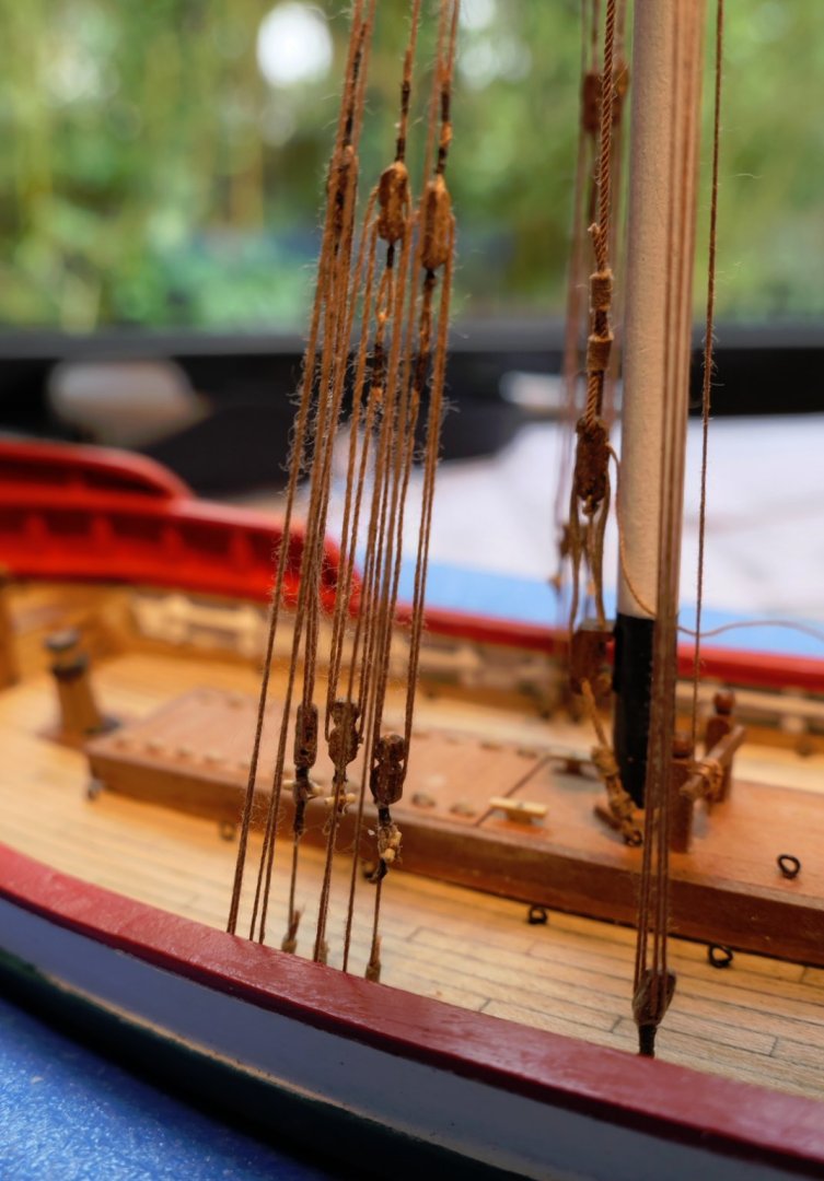
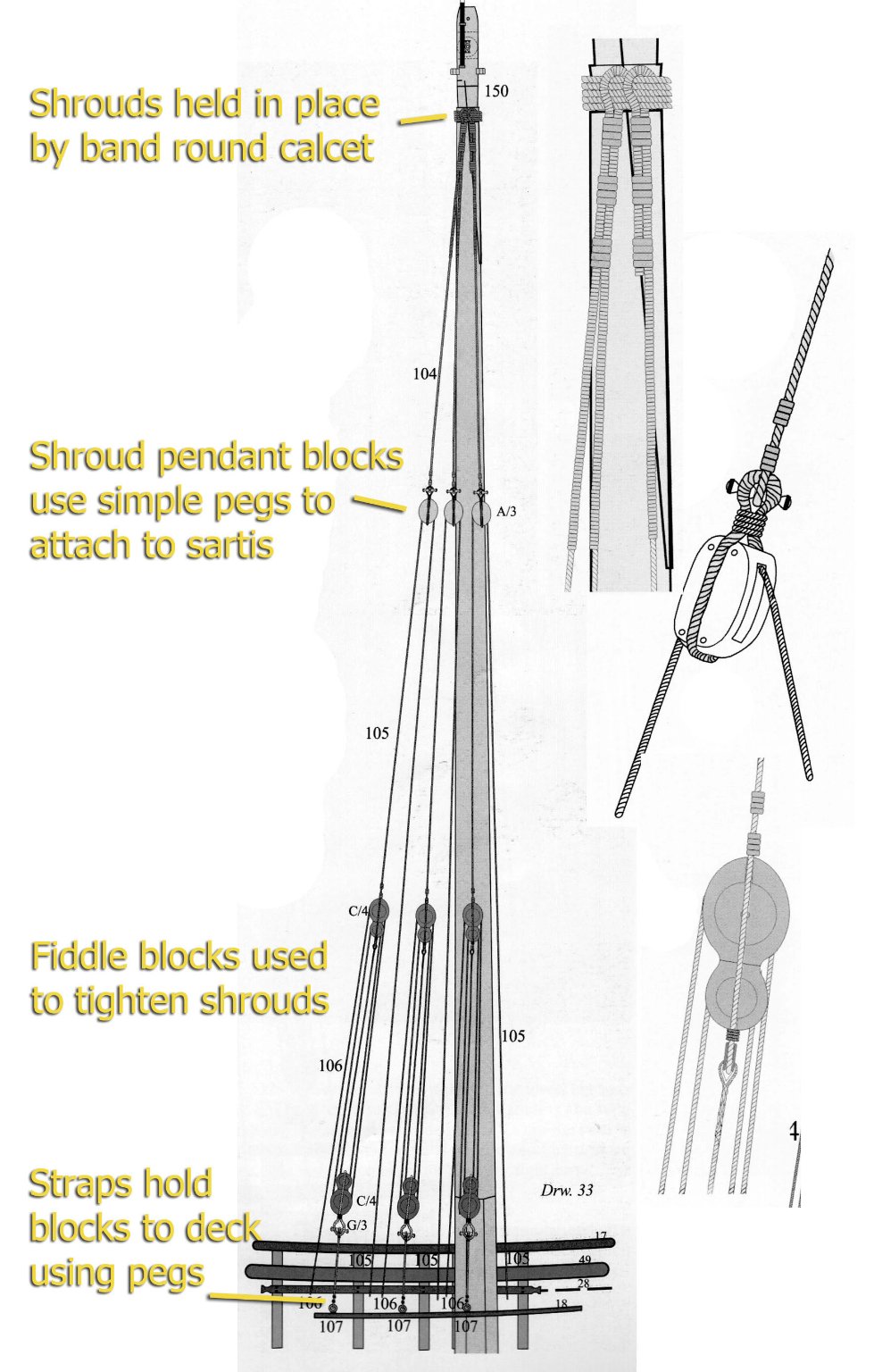
Back to the model. The layout of the shrouds is shown in the monograph as follows:

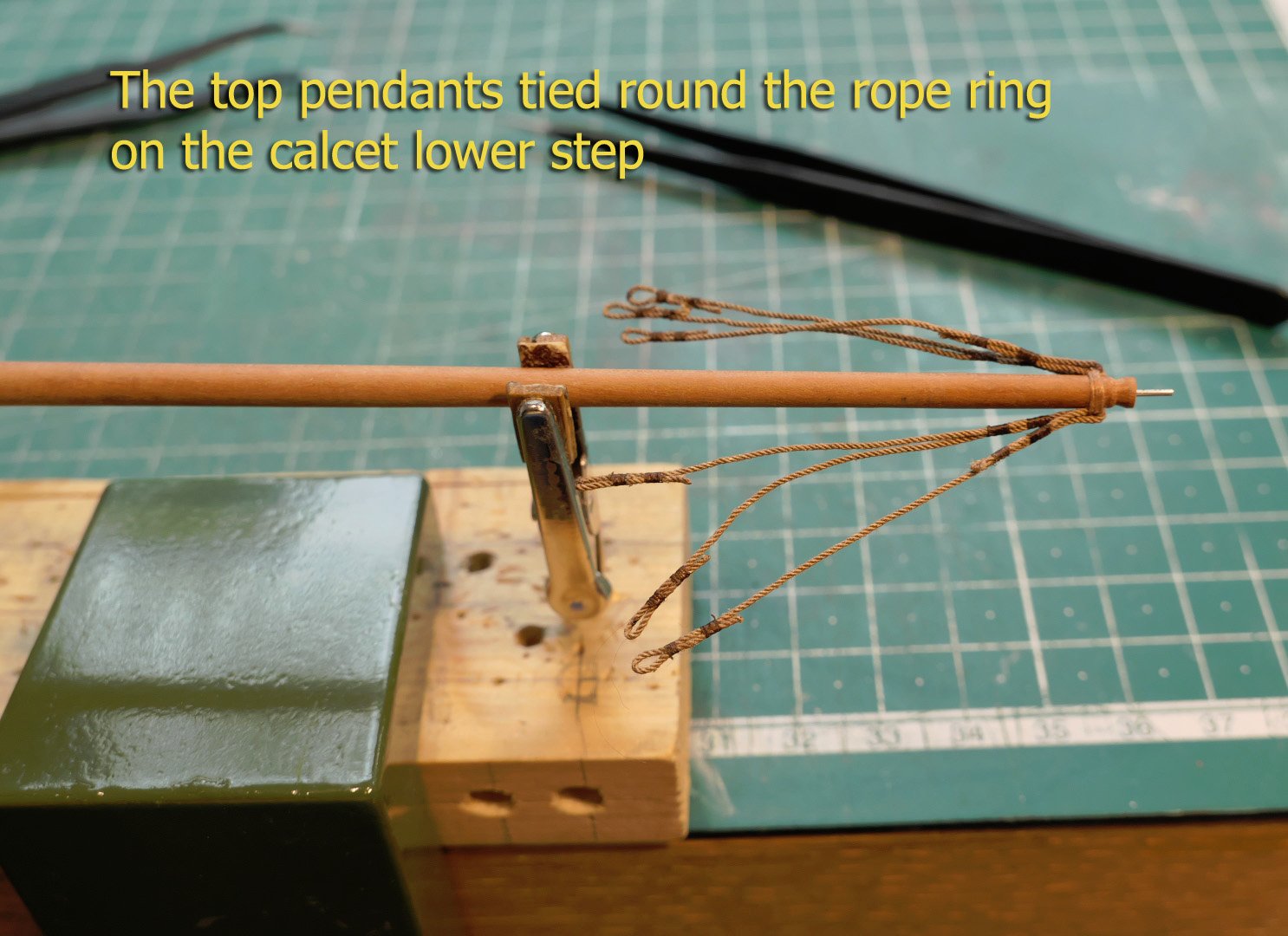
The key thing to notice is that the top pendants hang from a ring of rope on the lower step around the calcet, rather than going round the mast. Fiddle blocks are used to tighten the shrouds, and these are fixed to the deck by straps going through ring hooks in the deck. The fall of the tackle goes to the bars on the inside walls of the bulwarks.
Another thing to note is that the top pendant blocks are attached to the pendants by simple wooden toggles, as are the straps to the bottom fiddle blocks.
I thus spent a lot of time making these different components – the time being taken because I made many mistakes with the order of the rigging and so had to un-do then re-do several times. The sequence I finally made is as shown in the narrative below.
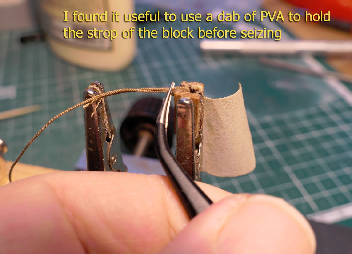
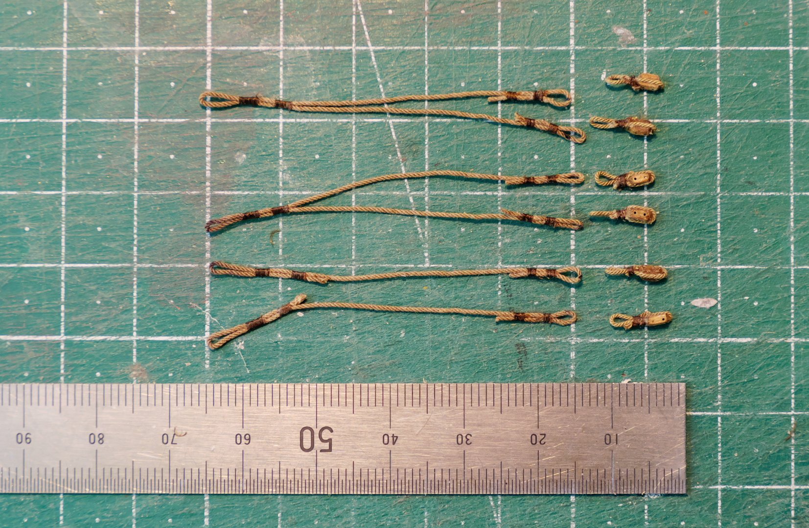
First were the top pendants. These have to have a loop at either end: one for the rope ring round the calcet, the other for the toggle from the pendant block. The top loop has to have a minimum diameter of 5mm, the lower a maximum of 1.2mm (to receive the loop and toggle of the block).


I forgot totally to take pictures of the bottom straps holding the fiddle blocks to the deck, but you’ll see them in the photos at the end of this posting.
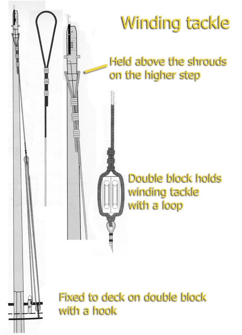
WINDING TACKLE
The winding tackle pendant is fixed round the top step of the calcet, seized, then attached to a double block which then forms a tackle with another block. The fall is attached with a hook to a ring bolt on the deck. The complete setup is shown in the monograph as follows:
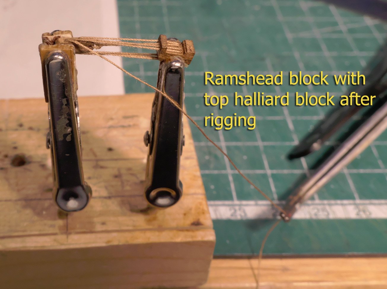
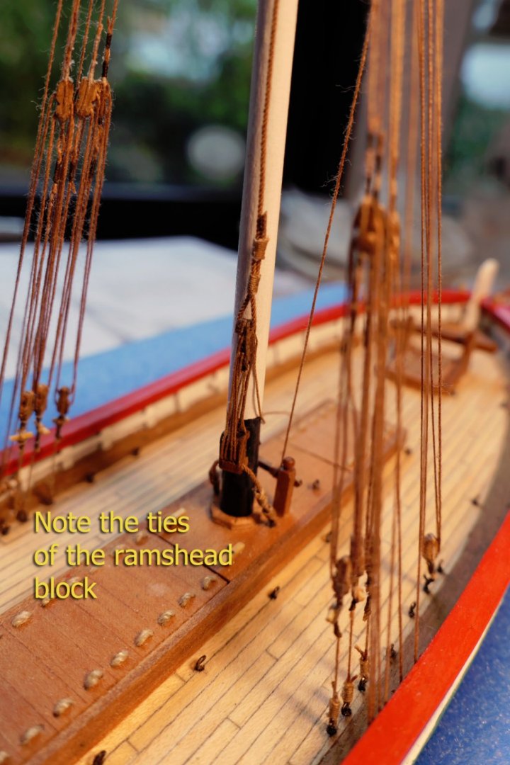
FITTING THE HALLIARD RAMSHEAD BLOCK
Before completing the fitting of the mast, it is important to fit the ramshead 4‑sheave block and its accompanying halliard block, as the ramshead block has to attached to the boards on the hatch covering with a strap.
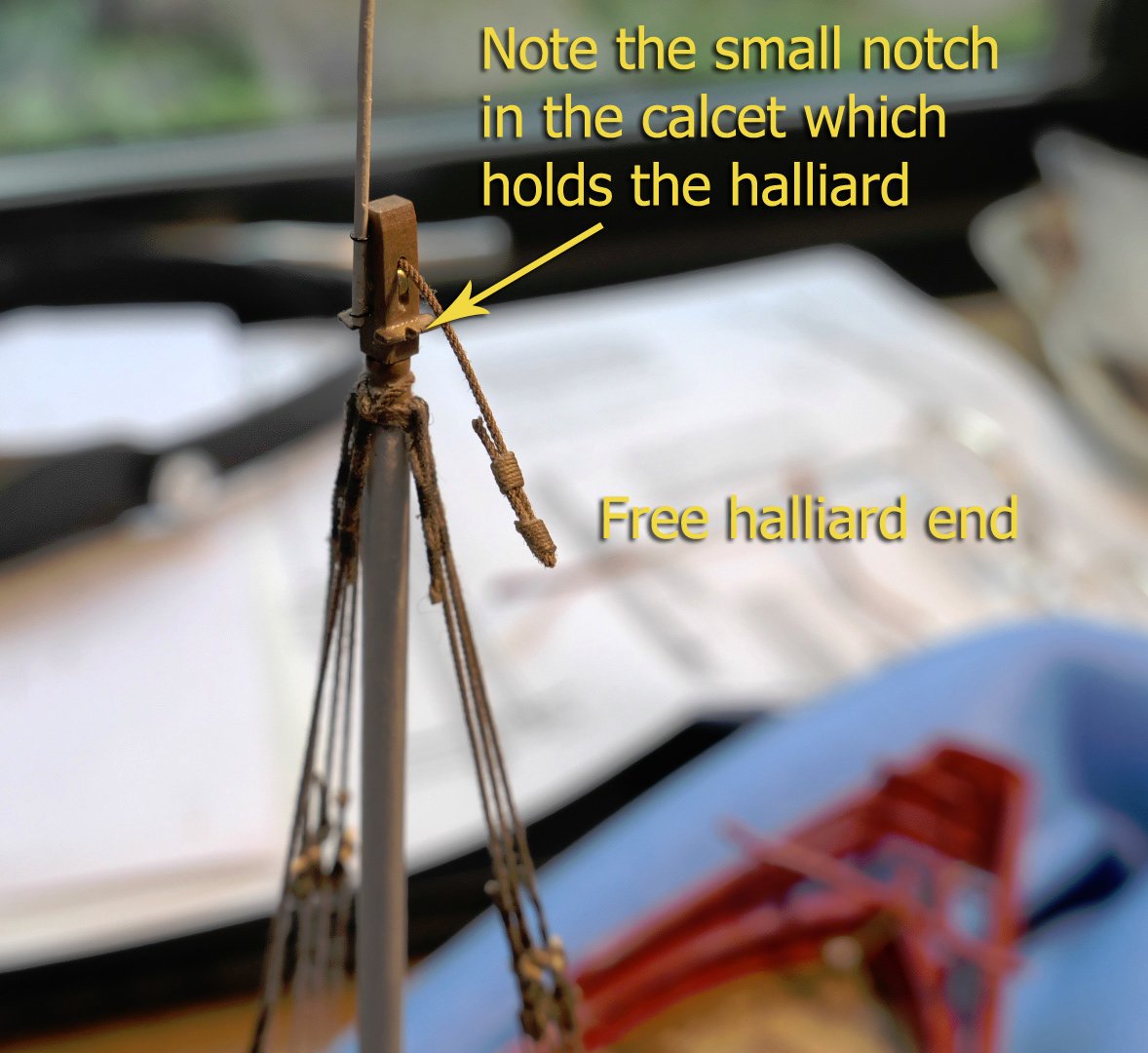
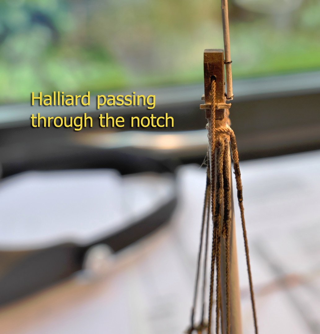
COMPLETING THE MAIN MAST FITTING
One of the details I had missed in the plans was the need for a small hole in the calcet protruding rim on either side to hold the halliard in place. I also placed the calcet in the wrong orientation, as the sheave should in fact run along the axis of the ship and not across. I decided not to try to undo all the rigging and kept this orientation. However, I did cut two notches for the halliard in the calcet, and these are at least functional!
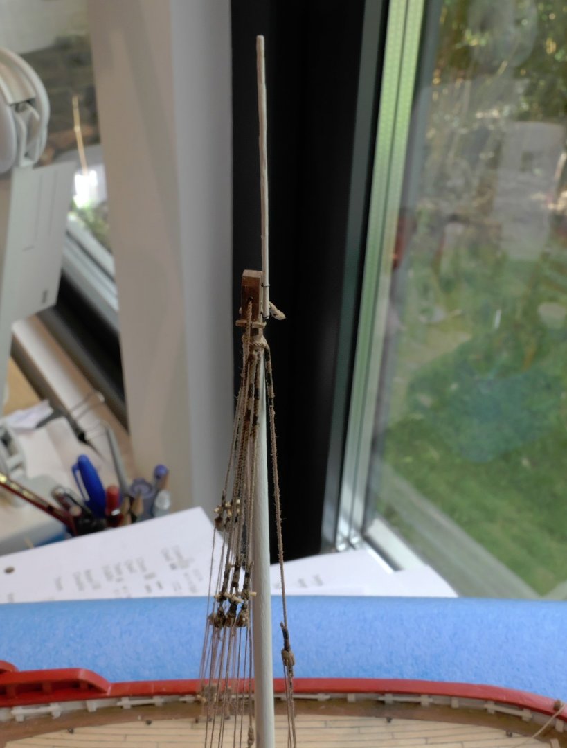
The blue foam holder I use while rigging is taken from some old packaging material.
You’ll note that the tiller is loose. This is because I removed the rudder after damaging the gudgeons several times when it was knocked by careless handling.
Now, with all that done, and after several un-doings and re-doings, I’ll start working on the lateen yard.
Thanks again for all the comments and likes!
Tony
-
-
Very neat indeed!
The only minor thing I noticed was the needle shaped end of one of the spiled planks. This of course is fine as it will be painted over, but in reality I don't think any plank would have ended at less than half its width. The strake in such cases would be resolved by a stealer or a drop plank. This is covered in the various planking tutorials available on this site.
Tony
-
8 hours ago, Bob Cleek said:
Realize that the boxwood rules and scales you're cutting up for modeling stock may well be worth a lot more than you think.
That's why eBay prices can go very high, the more so over the last few years; which leads to their cost per cubic metre being much higher than getting castello, and even higher than buying boxwood blanks.
Tony
- mtaylor, Bob Cleek, thibaultron and 1 other
-
4


Portfromfrontabove.jpg.832ebd17bd2a54748f73f8ee813ff055.jpg)


.jpg.50df049795c0647eeea25d959d246069.jpg)
.jpg.921b9fa7a7128124a51f85da9add8ead.jpg)
.jpg.e72401a16c6a86b05cd7a330cf1272f2.jpg)


.jpg.5442d1fcfeb22d235c1ab878087c4c95.jpg)


.jpg.7559ee21824fde8f551ae148458315ac.jpg)
.jpg.3218a4834eb5ec725c488c9a7178deb6.jpg)


Allège d’Arles 1833 by tkay11 – FINISHED - scale 1:100 - POB - from Ancre plans by F. Fissore
in - Build logs for subjects built 1801 - 1850
Posted
Thanks for the history of the flags, wefalck. I should have been more suspicious, as I had had a look at the history and the flag and the emblem on the stern panel are different -- the emblem on the rear looking the more accurate. What do you think? The flag and pennant are, however, as in the monograph. Maybe an equal oversight by Franco Fissore.
Tony