


mbp521
-
Posts
940 -
Joined
-
Last visited
Content Type
Profiles
Forums
Gallery
Events
Posts posted by mbp521
-
-
-
Eric, I found that EMT electrical conduit works great for stacks. It’s rigid and has a texture similar to the old iron stacks of the day. I found this after I used rigid copper tubing for my Cairo stacks, which I feel worked nicely as well. The conduit also gives you the hollow interior for a more realistic look. For the bands, on my Chaperon I used heat shrink cut into small strips, heated to the size of the stack, then I applied a thin layer of glue to hold them in place. This seemed to work fine, but when it came to making the bands on my Cairo I used aluminum tape (copper tape will work to). I used a love wheel on the underside to form the rivet pattern and then applied it around the copper tubing. I’m not sure how the Peerless’ stacks were constructed, but this is a couple of methods that have work for me in the past.
As for your windows, as several people have mentioned, I’ve used the clear plastic packaging before. They also make a glass compound that is made for model windows. I’ve also seen where people have taken the window frames, glued them down to a sheet of glass with clear Elmer’s glue, then gone in and filled the panes with the clear Elmer’s glue. After it has dried, the windows are released from the glass sheet with a razor blade and the outcome is similar to the olds style “rain glass”.
-Brian
- Canute, Cathead, FriedClams and 3 others
-
 6
6
-
Glad to see you back at it John. Sometimes a break is what’s needed to help prevent burnout. Nice bend on those cap strips, I’ve never been able to get my bends to hold their shape like the one sitting on the bow. Mine always tend open up a bit.
I’d love to see some pics of the buckboard. I’m sure it turned out just as nice as the work you are doing in the Chaperon.
-Brian
-
Keith, so sorry to hear about your Maggie. We will keep you both in our prayers for a speedy and full recovery.
-Brian
- Keith Black, mtaylor and Glen McGuire
-
2
-
 1
1
-
15 hours ago, KeithAug said:
beyond my experience. Is it possible to get good control of the width / depth?
It is definitely possible to control the laser output during engraving, cutting and scoring. While I haven’t worked my way up to engraving at different power and speed settings, I have used it on cutting and scoring.
Different thicknesses and types of materials call for different power and speed levels, so I would assume the same applies for engraving.
I believe that you and Eberhard on to something. I think I’ll try making a jig with the laser for two reasons. The setup is easier with the laser. I am almost guaranteed a true square grid for the rails and second, the only table saw that I have is a 10” industrial that wouldn’t allow me to cut a narrow enough kerf for the size brass rod (1mm) I am using.
I just ordered a bottle of solder paste to give that a shot so I may sit down this weekend and see if I can build up a jig. I’ll keep everyone posted as to my progress.
-Brian
-
2 hours ago, wefalck said:
- I think, if you cut a half-round seat for the handrail into the uprights using a burr and then use solder-paste that should work.
- likewise for styrene rods, a half-round seat in the uprights and other joints locates the parts and requires less cement - I would use styrene cement, which welds the parts together, rather then glues them.
Eberhard, thanks for the tips. I haven't sold myself on the styrene rails yet, so I may give that a try. I just looked up solder paste and from the videos I watched it makes it look almost too easy. That's what scares me about it, it looks too easy.
") 54 minutes ago, KeithAug said:
54 minutes ago, KeithAug said:That is hell of an extensive update Brian - and all those laser cut pieces are making me jealous. As for the rails, is styrene going to be durable enough? Presumably if she is going into a case it will be OK. The dusting could be problematic if it is not being cased. I have a way of getting the brass option very regular if you are not wedded to the styrene option. Let me know if you are interested.
Thank you Keith! It only extensive due to my lack of updates. I get to working on the boat, taking pictures, then life takes over and the next thing I know a month has passed and I have a 100 pictures that I need to upload and write about. As for your offer to show me how to go with the brass method, I will definitely take you up on it. I will have to use brass on the railing on top of the pilothouse. The stanchions are spaced too far apart and the rails are much to thin to use styrene on. Please feel free to share.
57 minutes ago, Cathead said:Oh, wow. And here I was telling myself it was ok to be moving so slowly on my riverboat because Brian wasn't making much progress either. Oopsie.
Thank you Eric, too funny. My progress has been lurking in the shadows, and I do think that you are moving along at a good pace. Besides, perfection takes time.
52 minutes ago, KeithAug said:he sold both of us down the river.
I see what you did there.
-Brian
-
Hello again everyone,
I figure I had better get some progress shown on her or people may start to lose interest. It's not for lack of work being done on the Caroline, it's just laziness of not updating the build log. Since my last update a month ago I have been busy and I have been giving my XTool quite the workout.
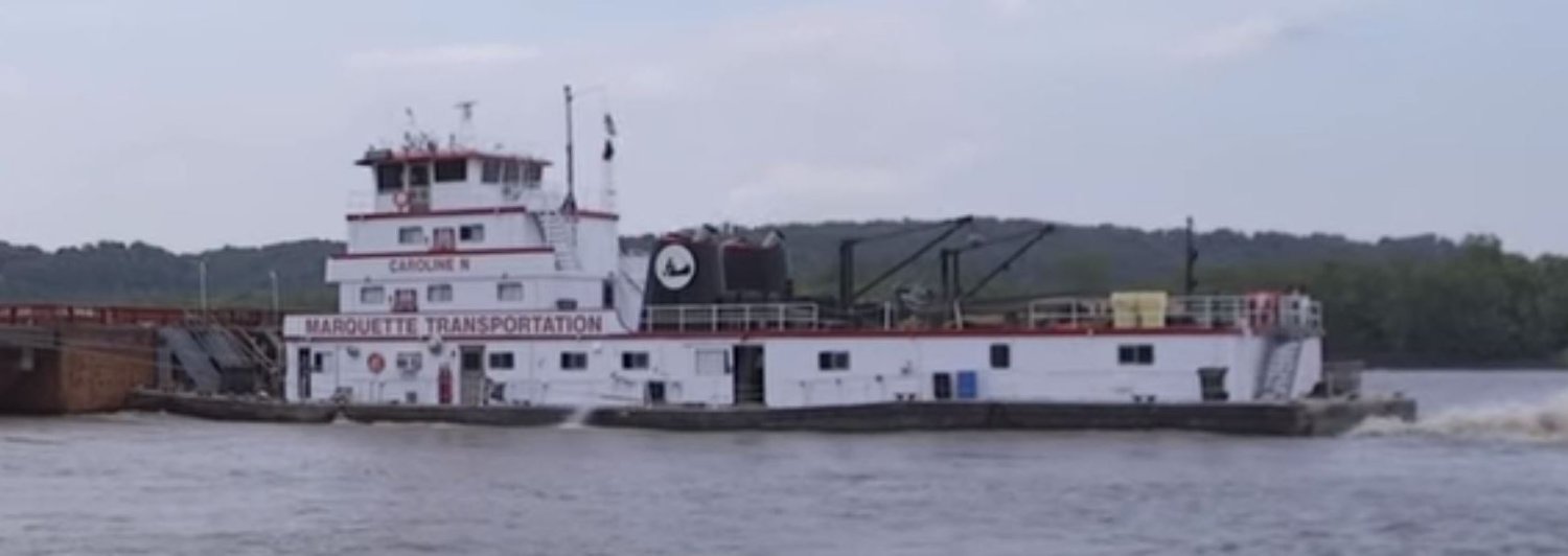
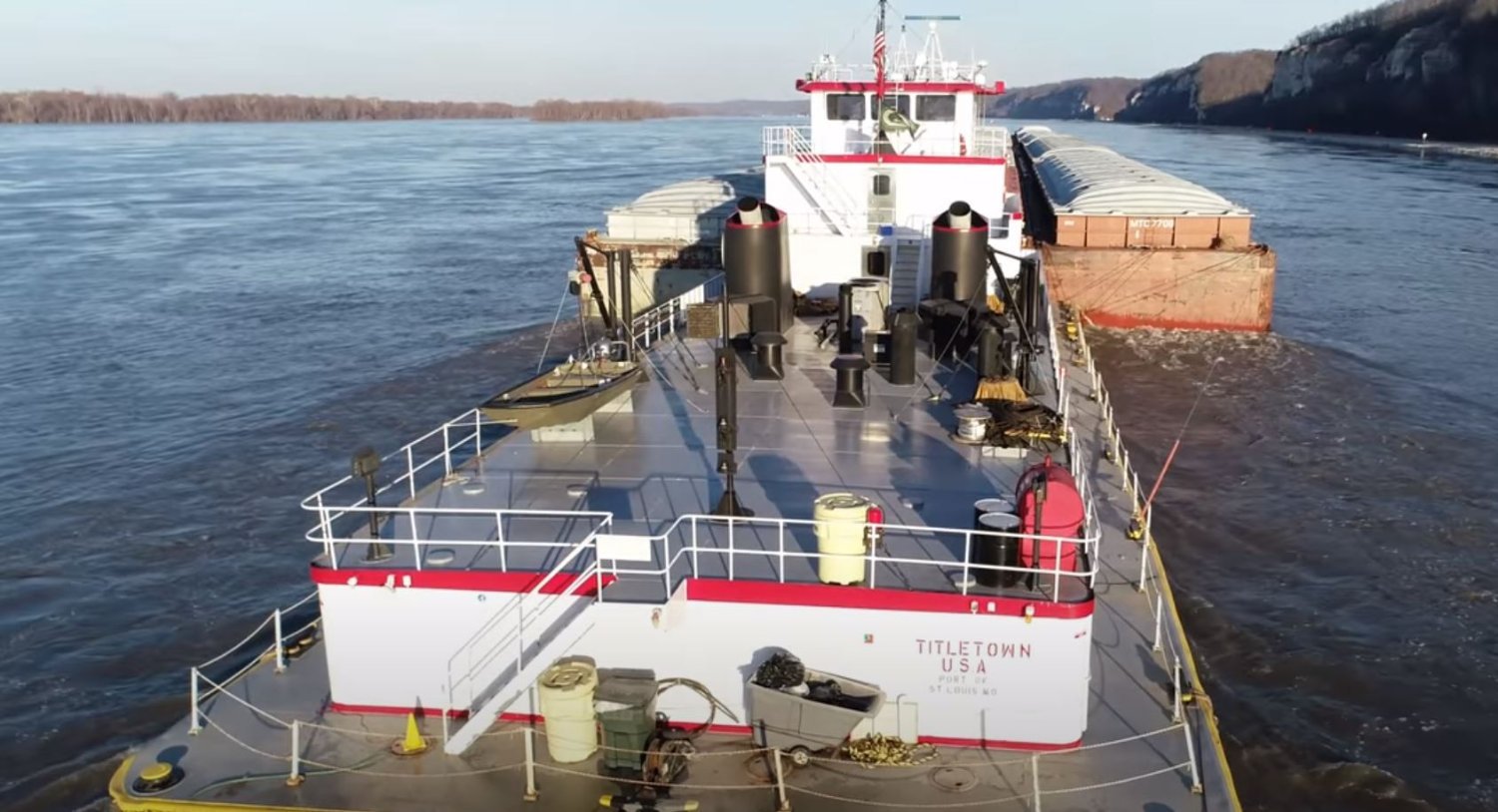
So i was able to get all of the deck walls drawn up, cut out and assembled. These were real simple shapes to work with. The main roadblock that I kept running into was the window locations on each of the decks. I first located them all according to the plans, but then I started finding videos of the Titletown USA (Formerly The Caroline N) and discovered that the windows were not all located in the same location as the plans. So I had to do a lot of research of the videos to get the right angle so I could properly locate the windows. I did this by scrolling through the video to the right spot, pausing it and then taking a screen shot the image. I think it worked pretty well and I believe that I have all the windows and doors in their correct locations.
Once I felt confident that I had everything correct, it was on to getting the deck walls cut out and assembled.
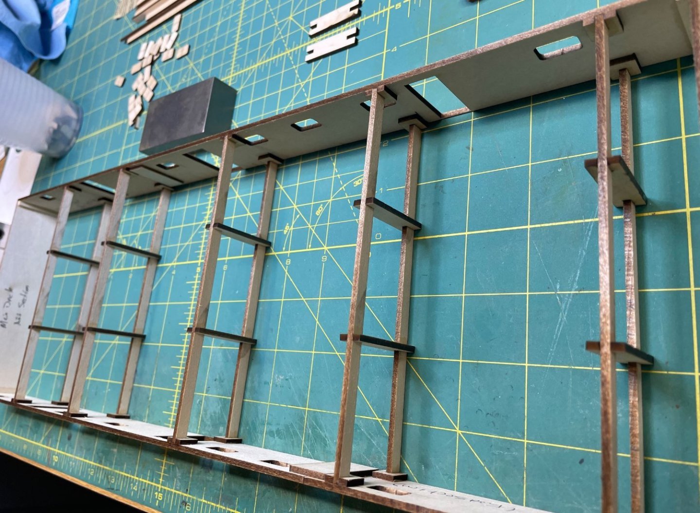
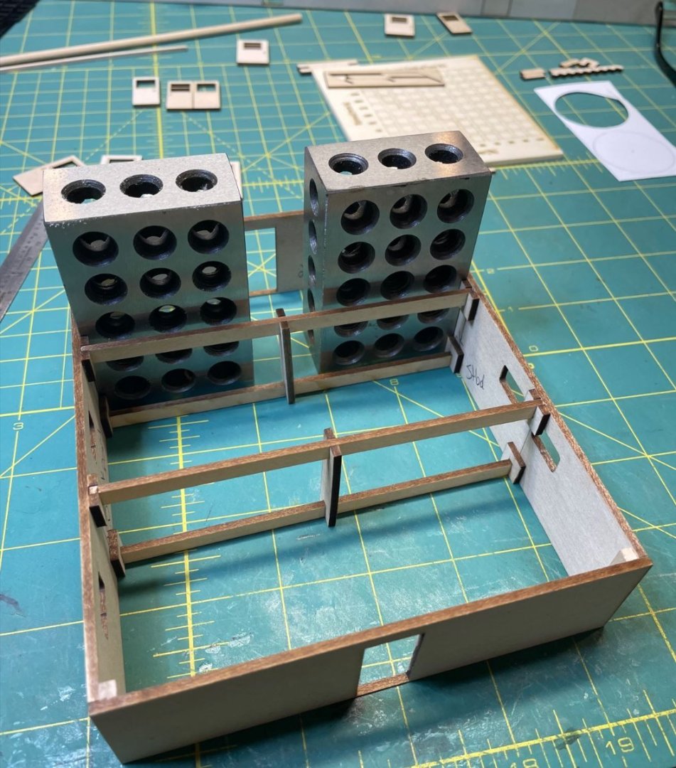
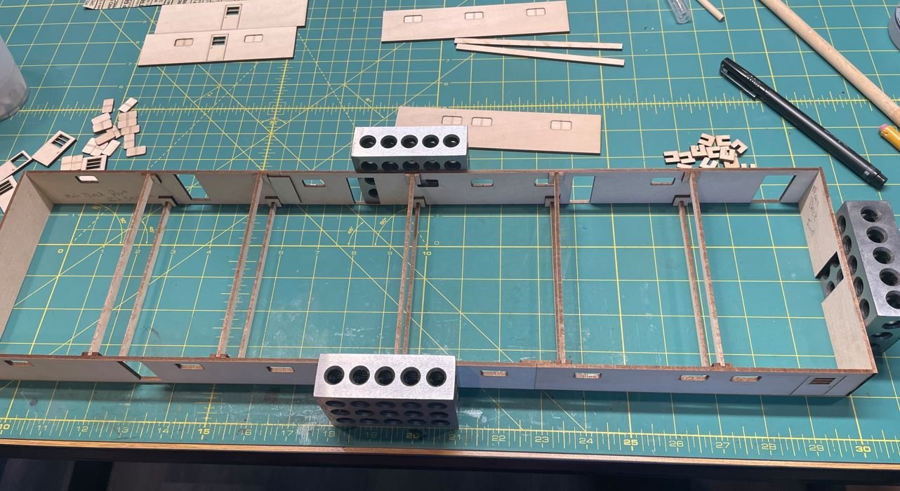
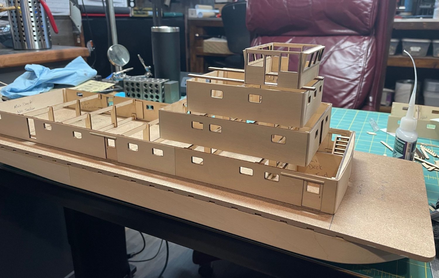
Here is the main deck going together. I cutout some cross bracing and brackets to add some stability to the structure and to give the deck a stable mounting surface.

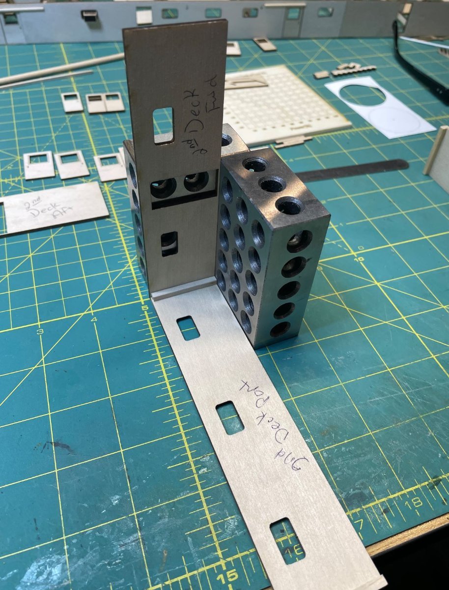
Second deck going together.

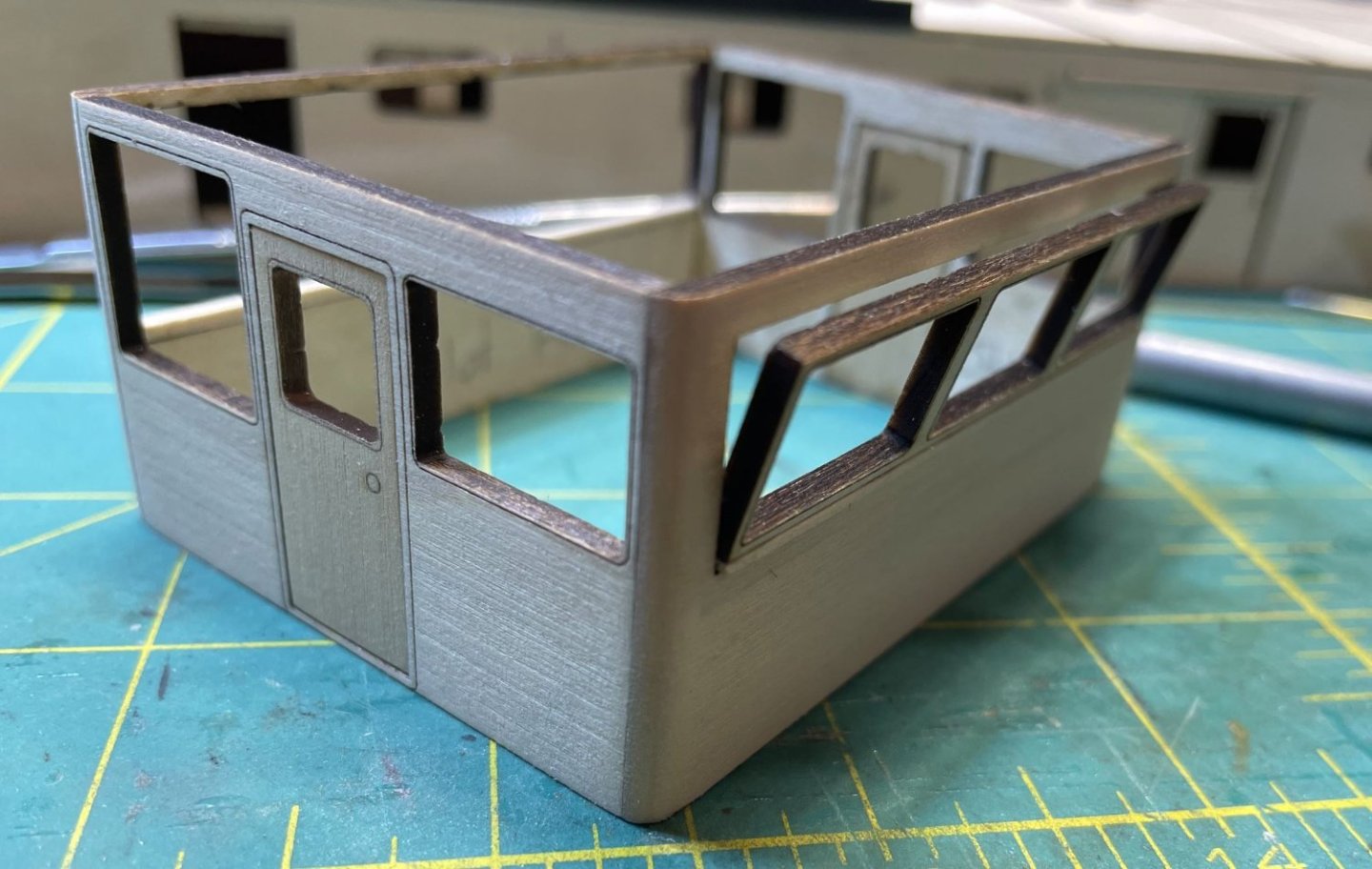
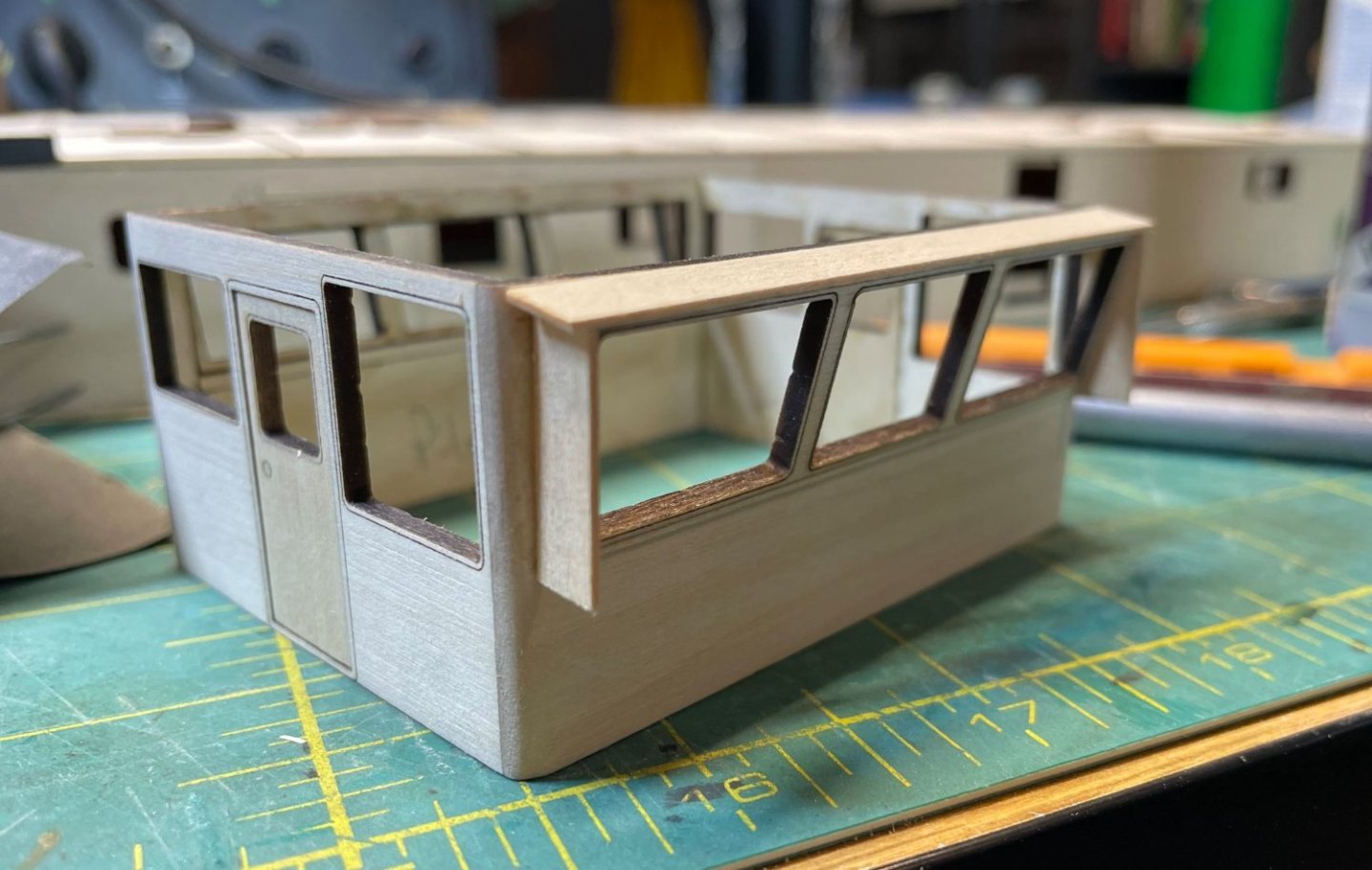
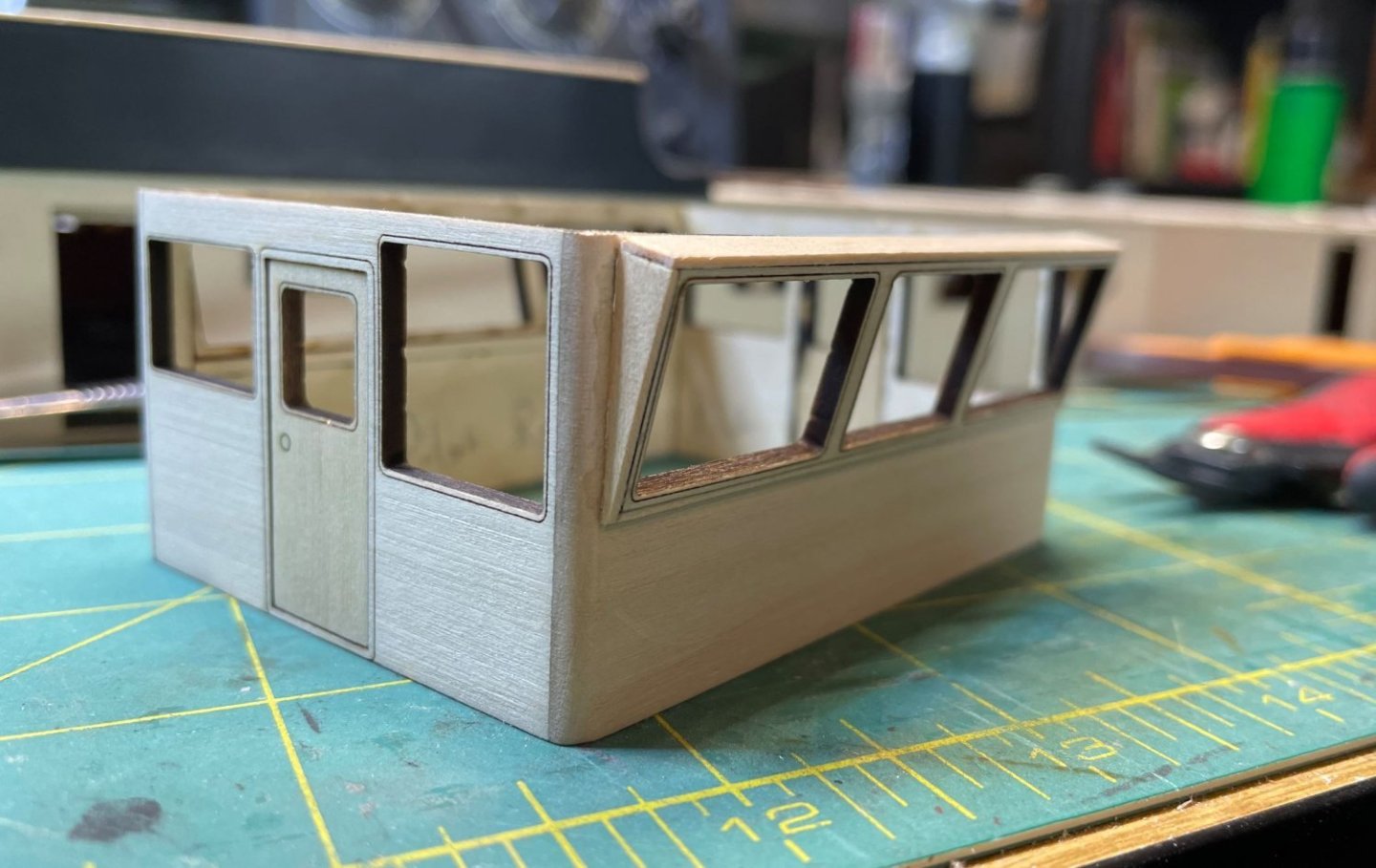
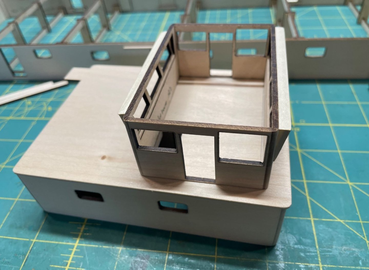
Pilothouse assembly

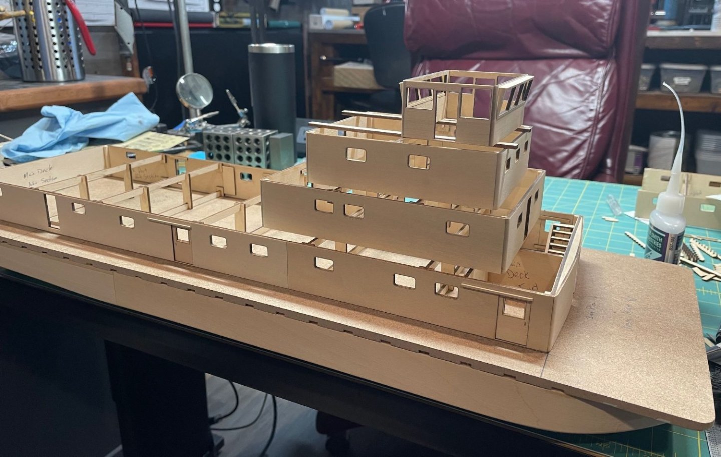
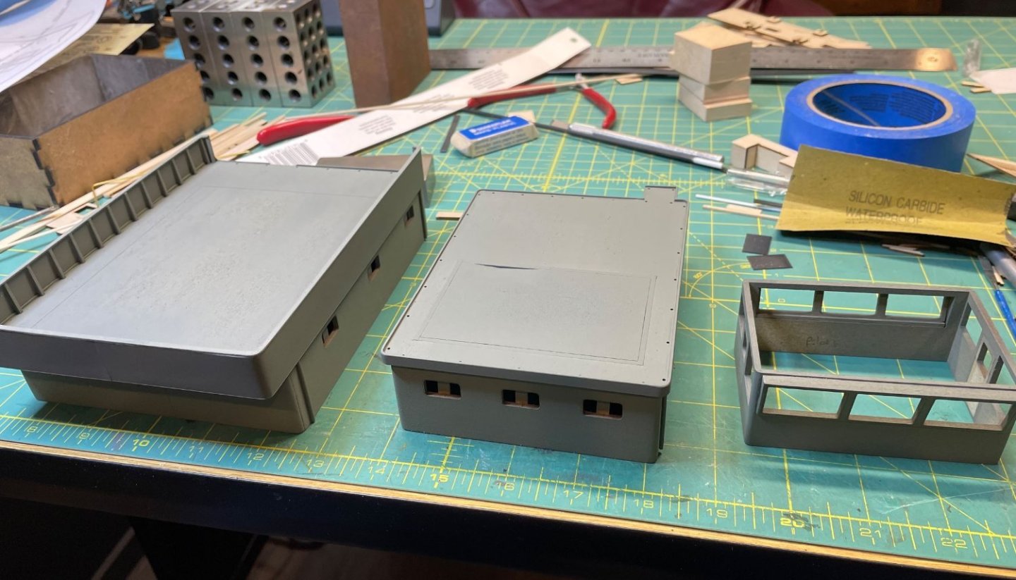
And all the deckhouses assembled and resting on the hull.
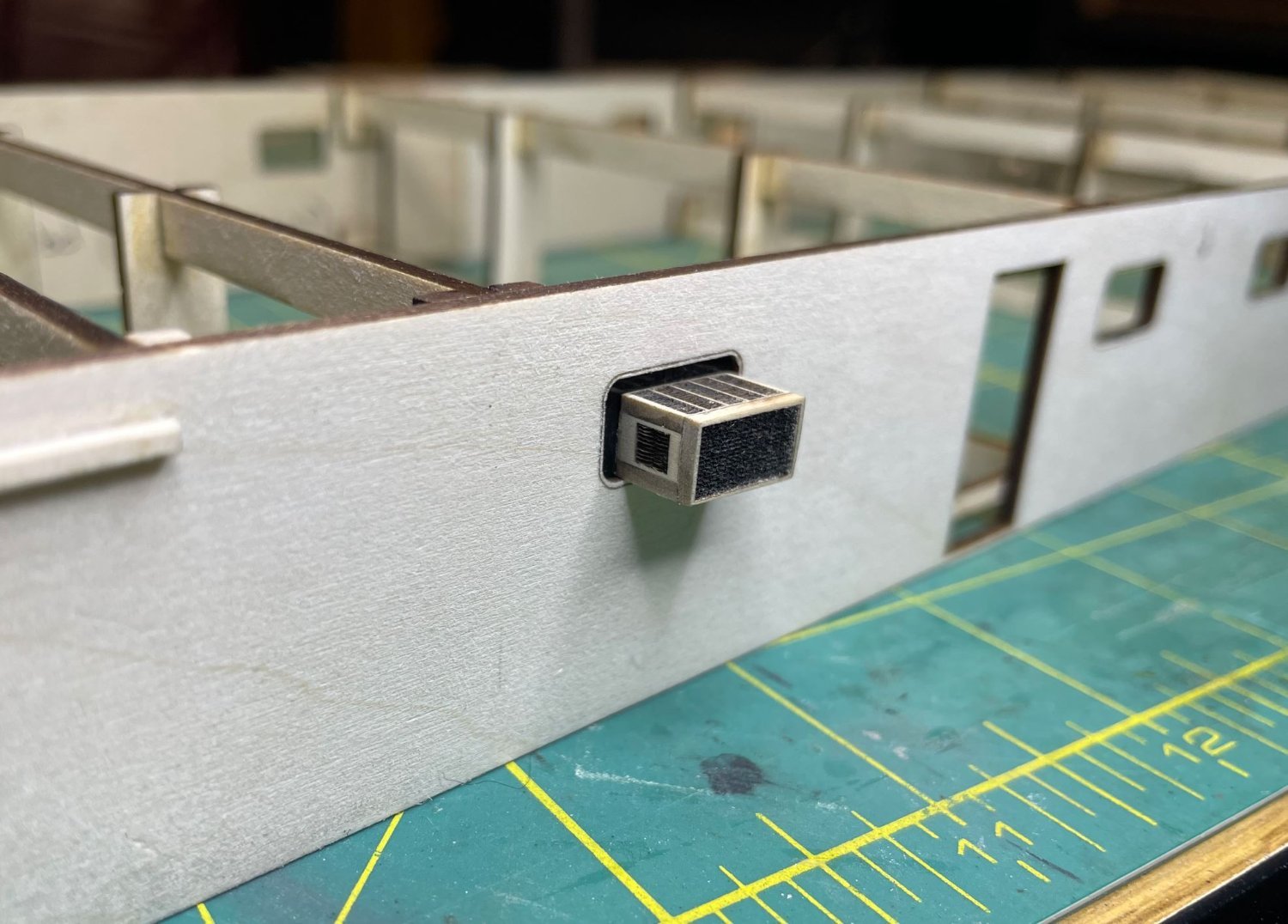
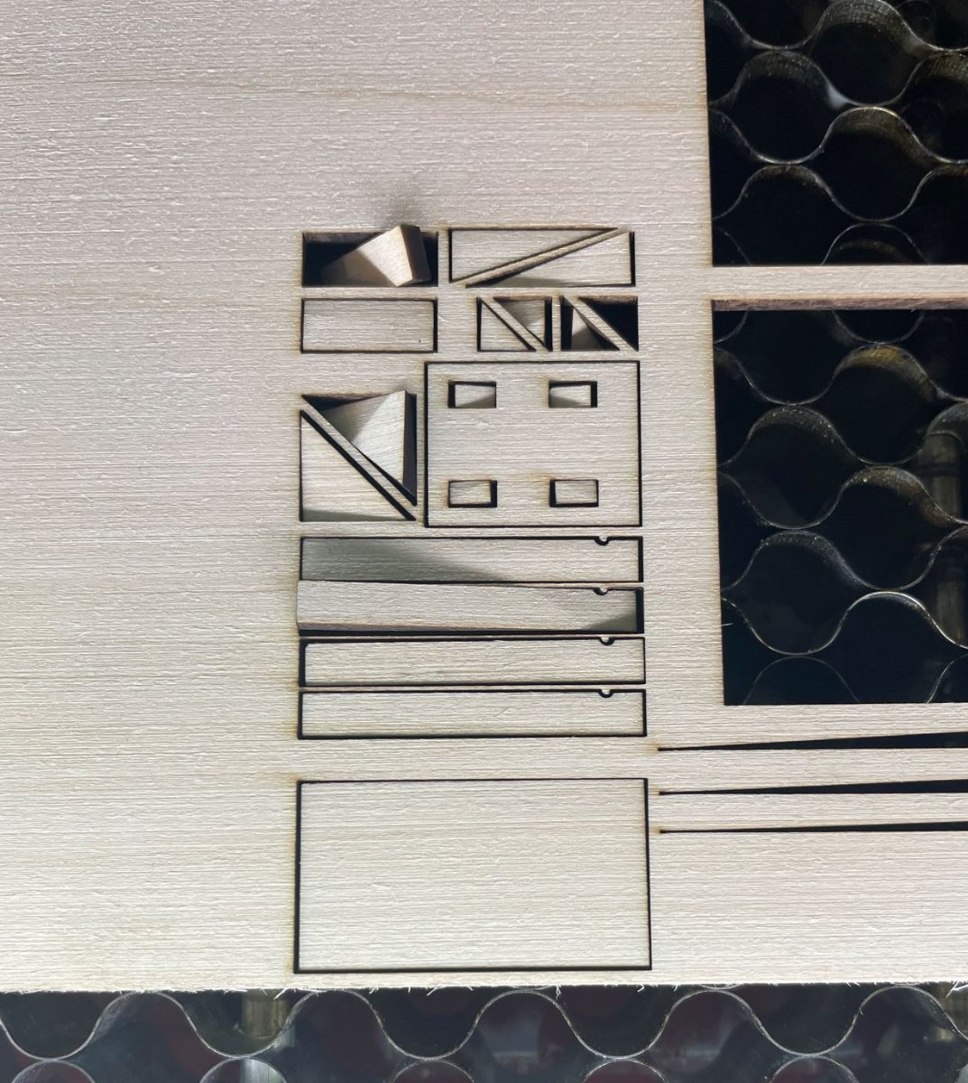
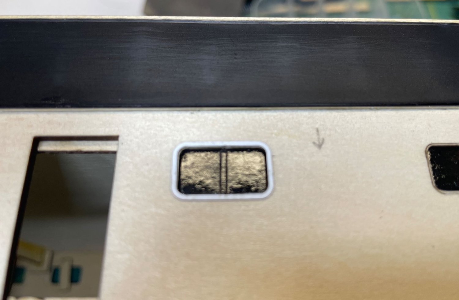
So I wanted to play around with some of the smaller detailed pieces, just to see how they would turn out. I started out with the window unit that sits in one of the galley windows. I assume that it gets a bit toasty in there when the cooks is preparing the crews meals.

I started with the five pieces that make up the unit. Apologies for the blurry picture, I phone had trouble focusing on the tiny pieces.
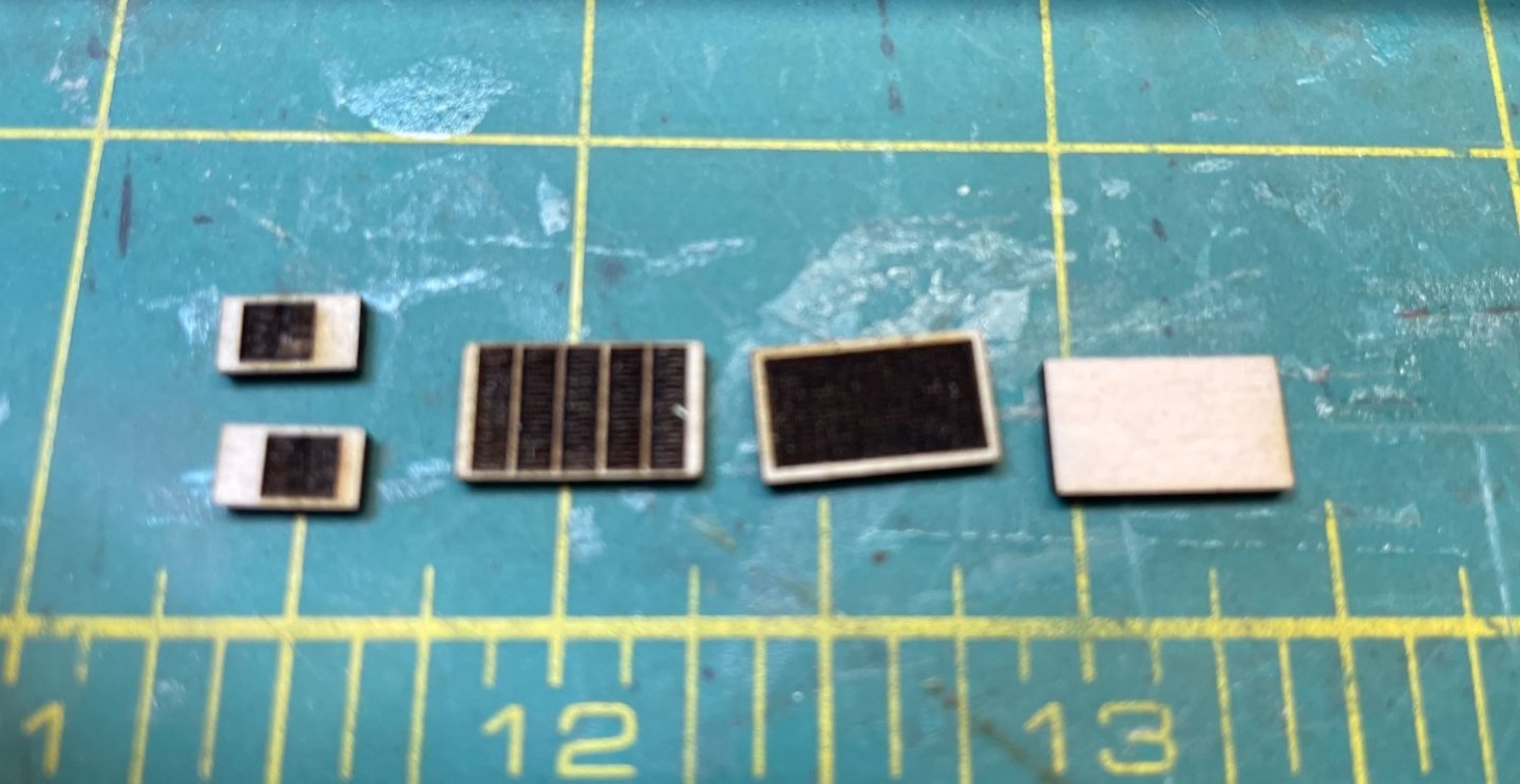
The assembled window unit.
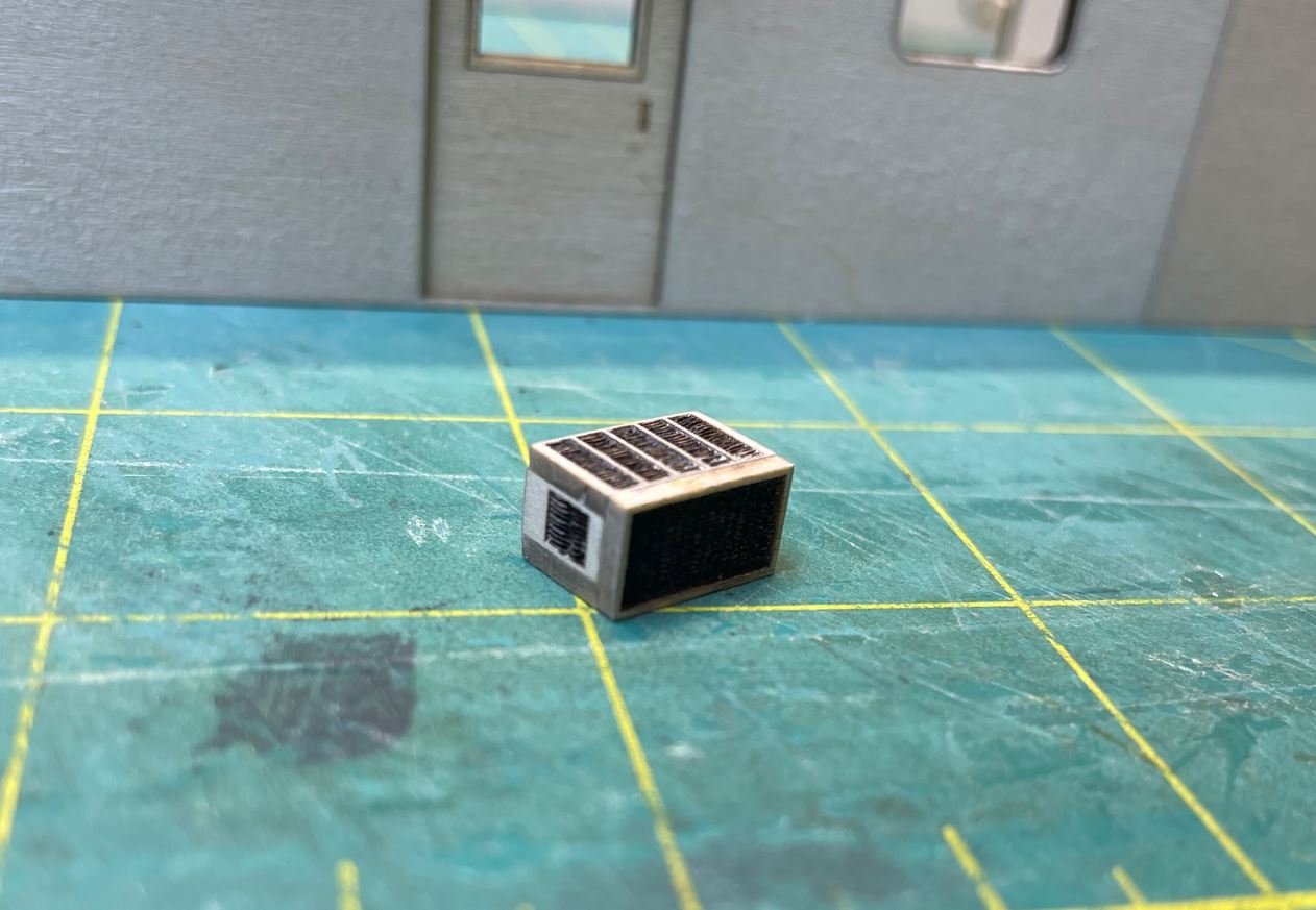
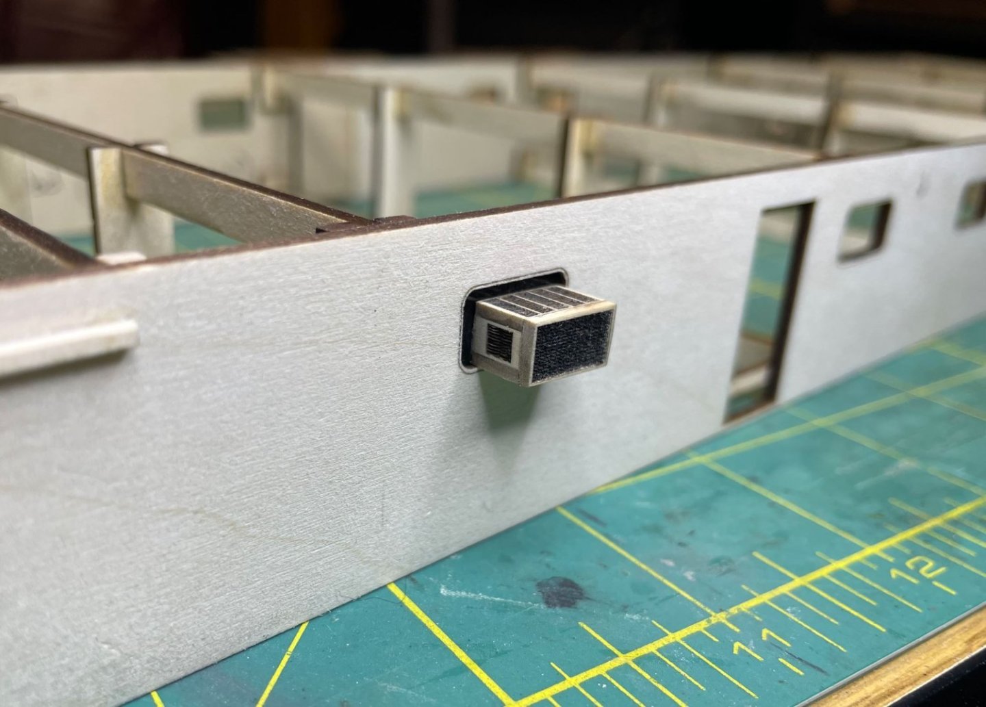
I used one of the blanks from the window cutouts and glued the window unit to it for that perfect fit. Not too terrible.
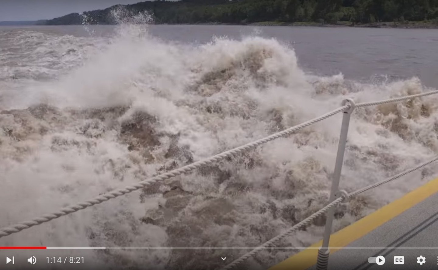
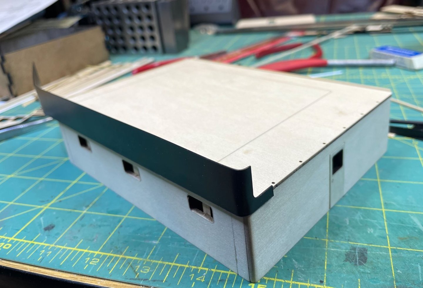
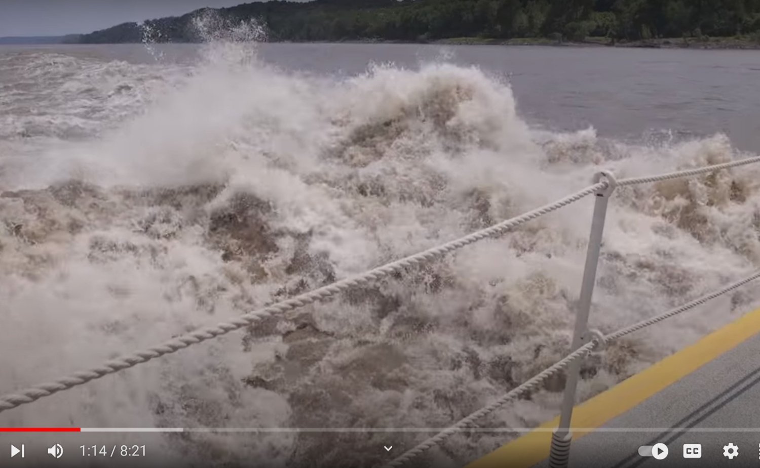
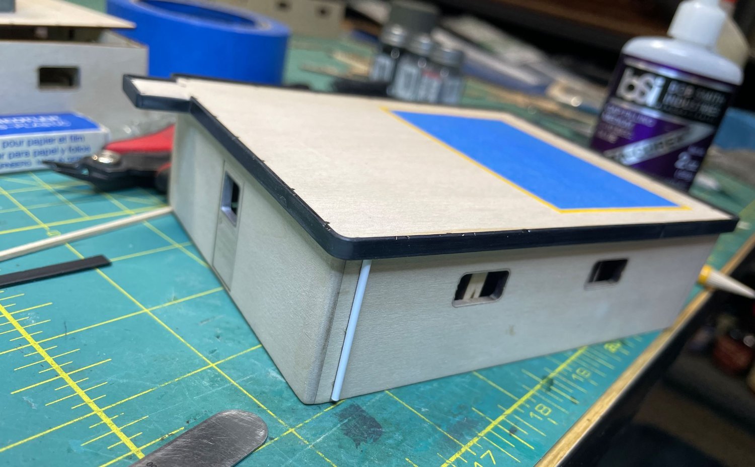
Next up, I wanted to work on the hull some and get the contour of the deck set. There is a slight rise in the bow and stern areas that I needed to build. I am assuming that the bow rise was to keep the waves from coming over as well as giving a higher surface area for contact with the barges. As for the aft rise, my best guess is that it just helps keep the churned up water from the props from coming over since this area can get a bit turbulent.
Profile of the boat showing the bow and stern rise.

Waters get pretty churned up at at the stern.
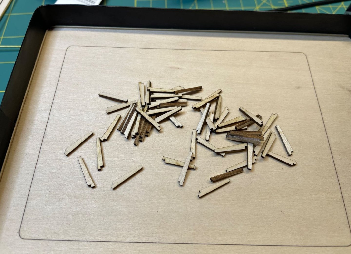
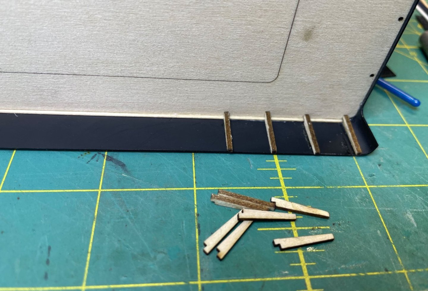
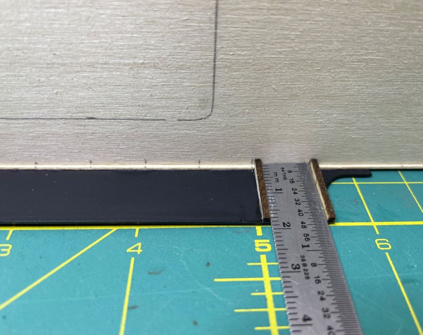
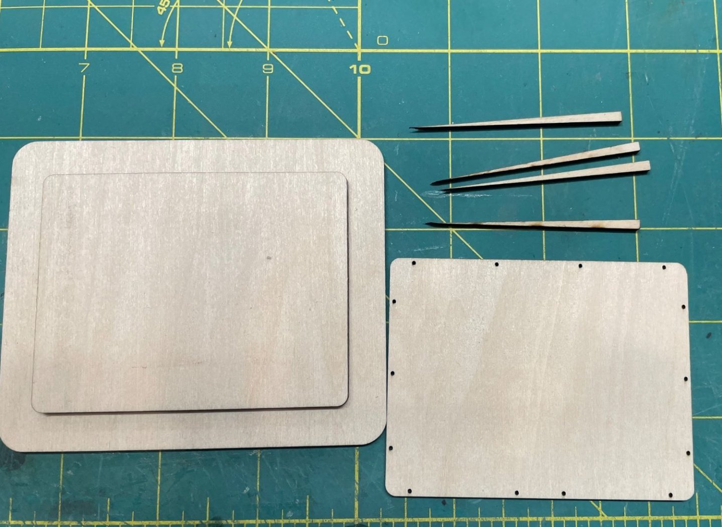
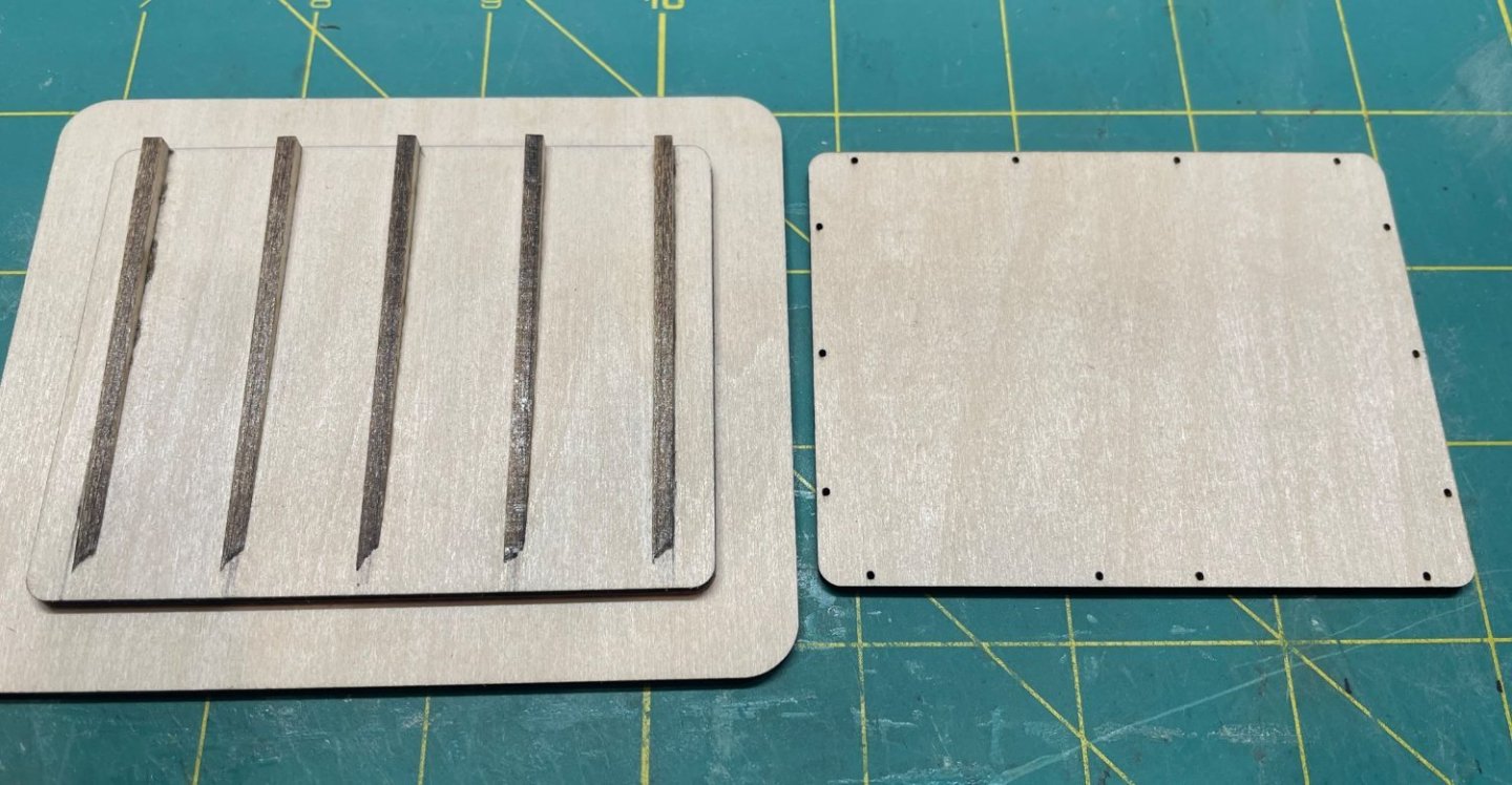
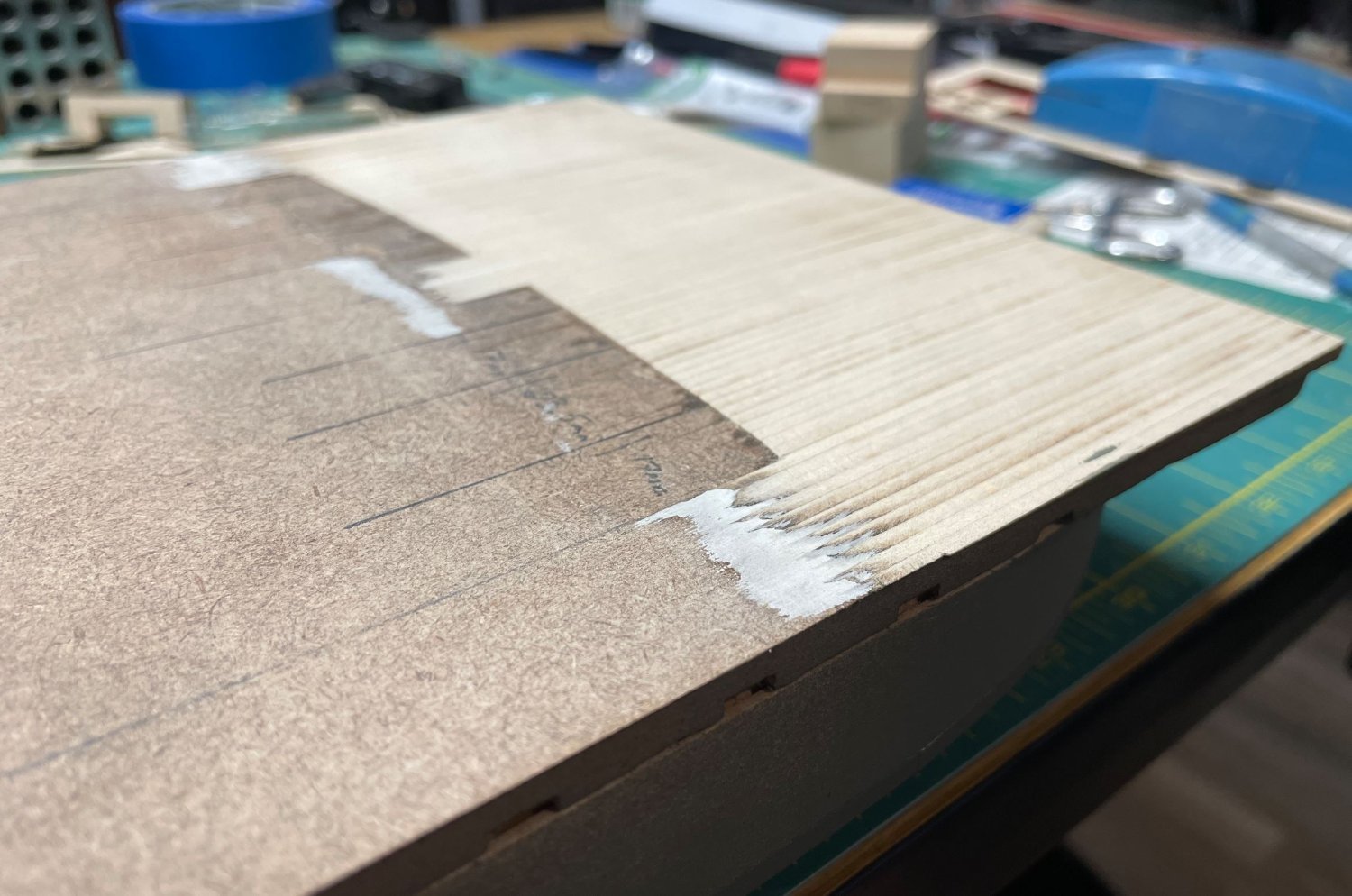
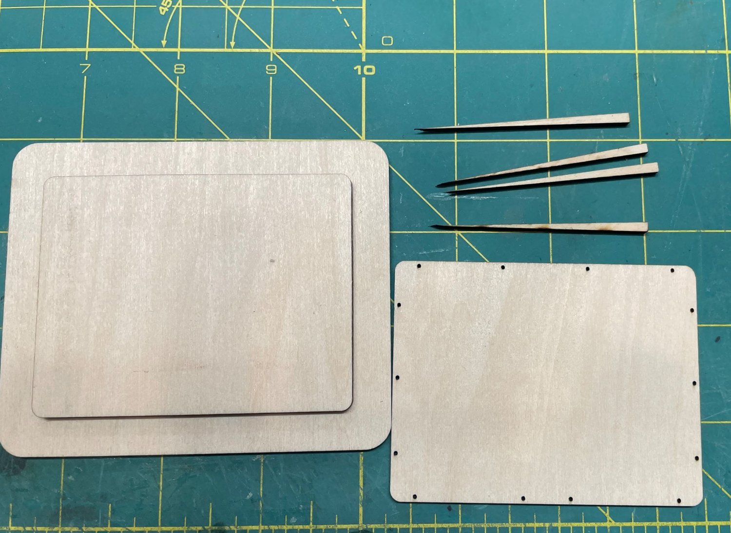
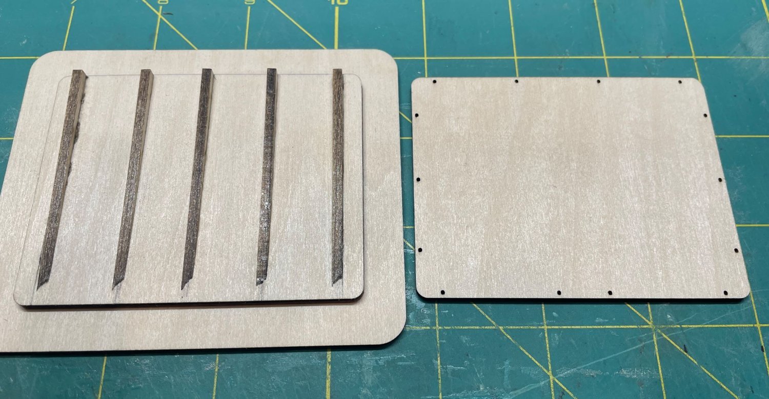
To add this rise, I cutout a bunch of basswood strips that tapered down from the full rise of 3mm at the stern to 0mm and from 4mm at the bow to 0mm. I glued these in place and then for the stern I cutout some plywood panels to raise the deck beyond the rise.
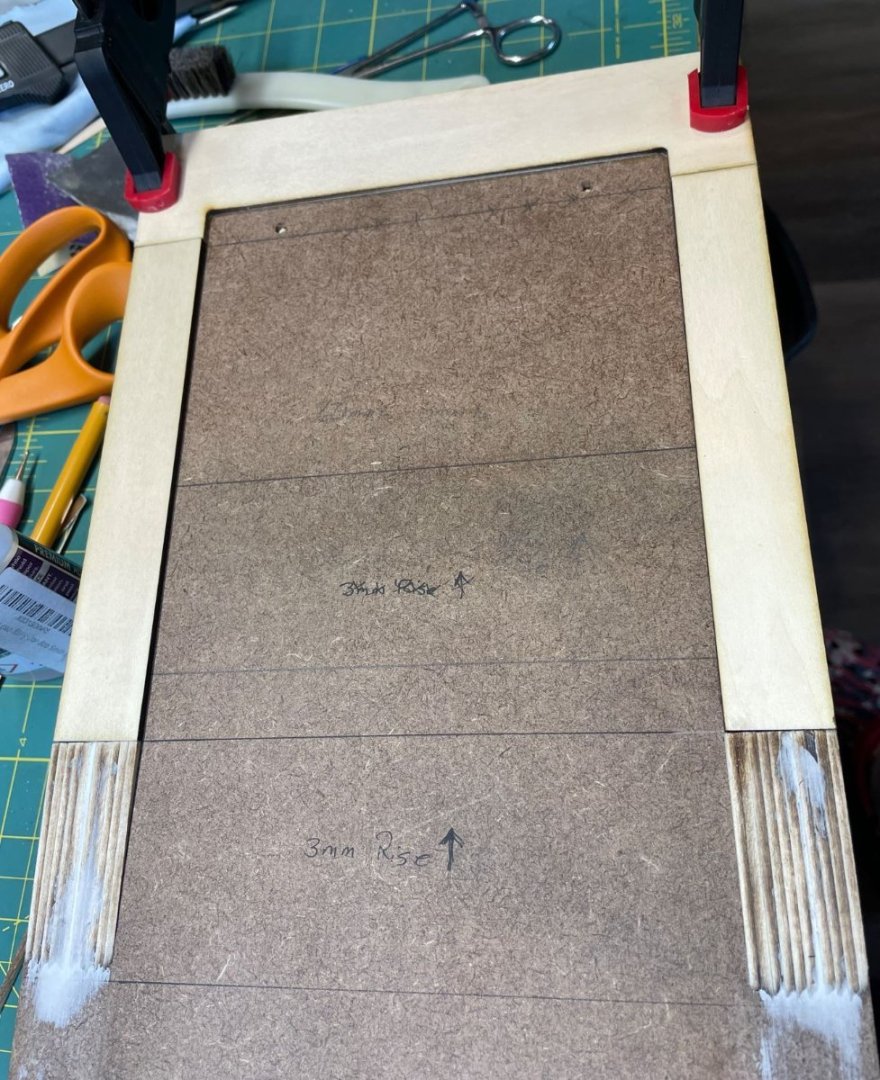
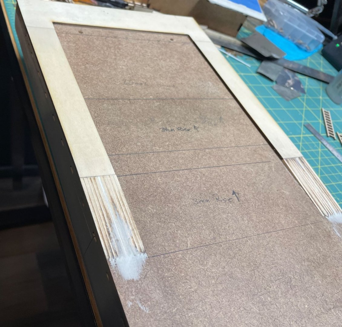
For the bow section, I just glued down the strips from the forward end of the deckhouse to the bow since the rise terminated at the very front.

Since the bow rise starts before the front of the deckhouse, I trimmed the strips back a bit to coincide with the front of the deckhouse. I thought this was easier than trying to trim the correct amount off the bottom of the deckhouse and maintain the correct angle without any gaps.
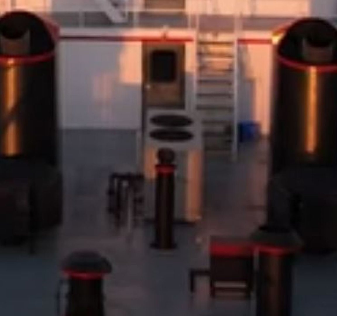
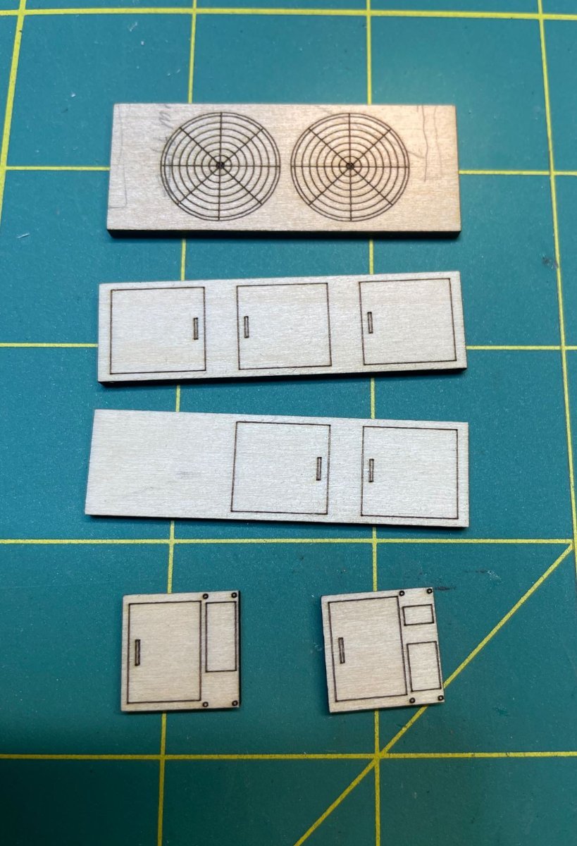
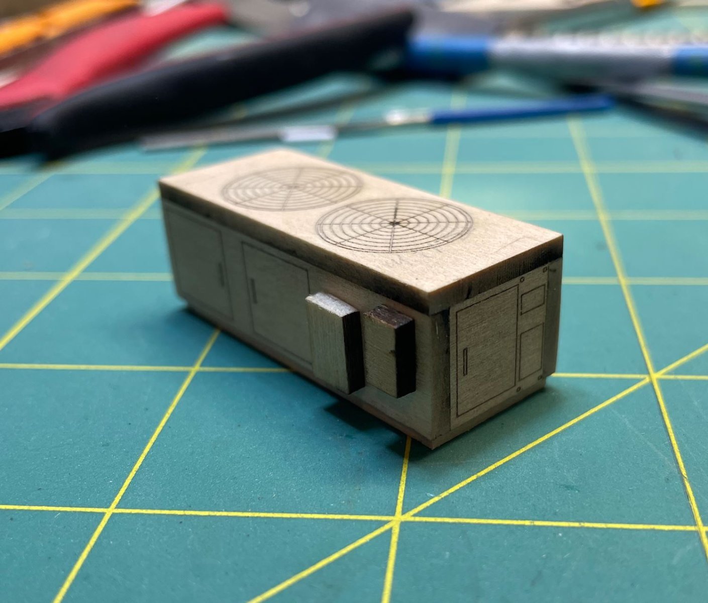
Next I wanted to play around some more with some of the deck details, and since I was on the AC unit kick, I figured why not build the main AC unit. This unit sits between the two funnels on top of the main deck. Kind of hard to make out since I had to zoom in quite a bit.
Once again, I drew up the pieces and added some details like the door panels and the protective grill that covers the fan blades.

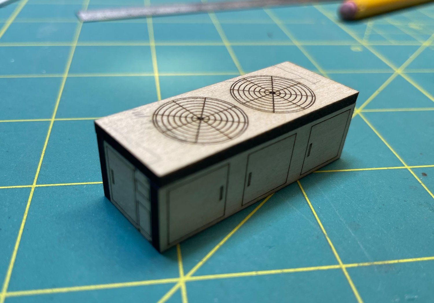
Glued all the pieces together
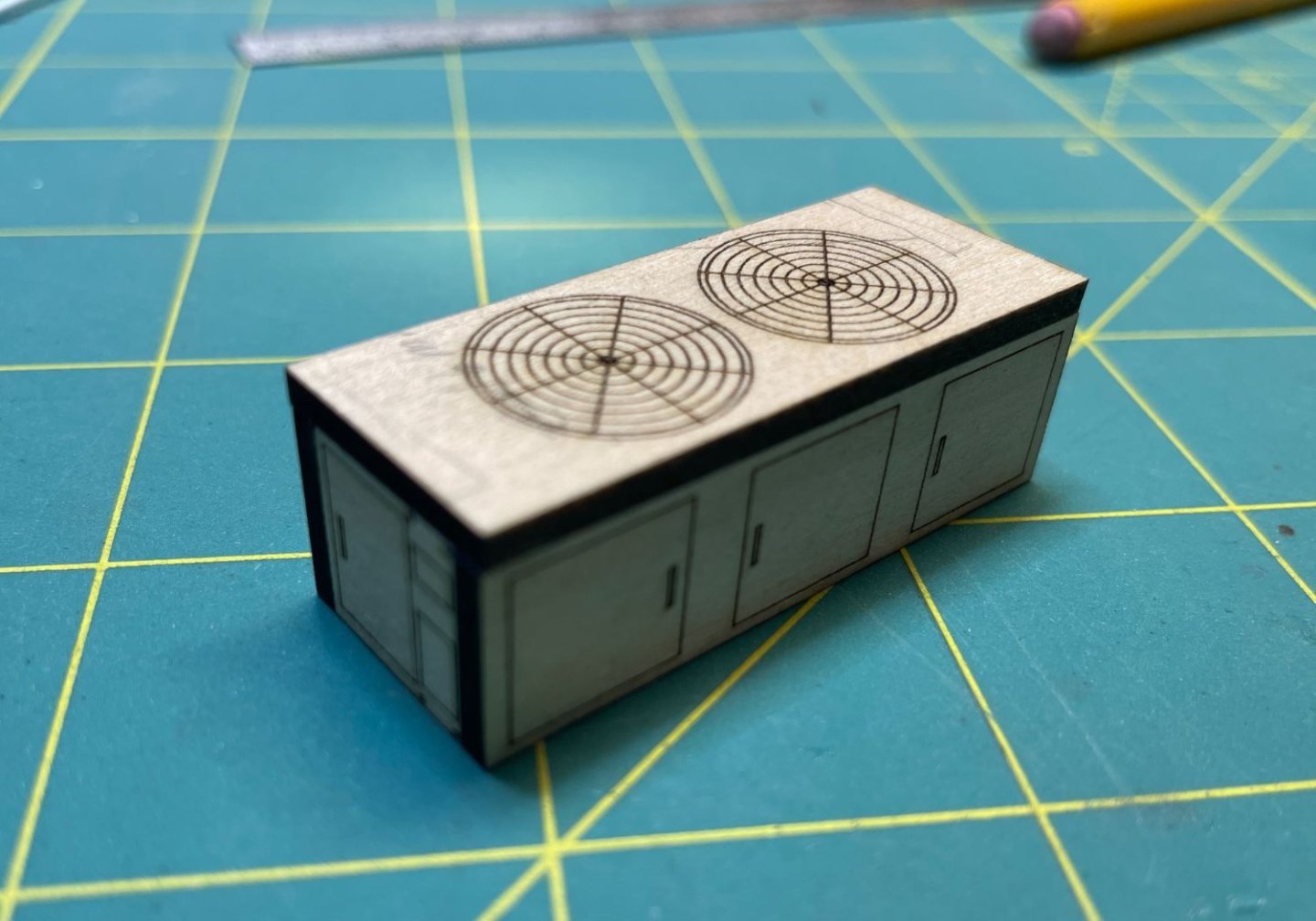
then added control and power boxes to the assembly. I'll get this painted up later on and add some drain lines and power conduits once it has been installed.

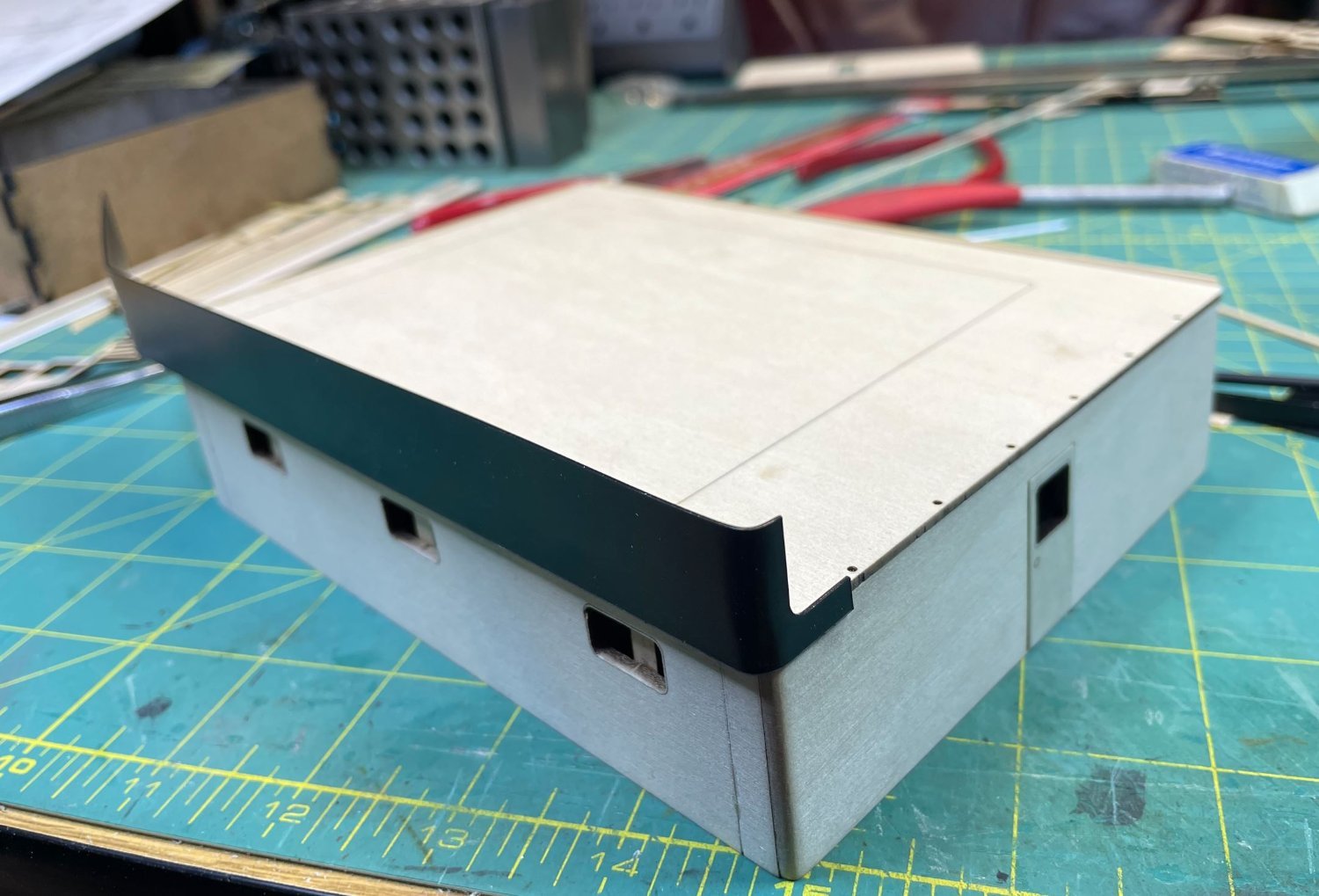
Now it was time to move on to building up the trim and railings for the upper decks. Starting with the second deck I added the forward railing bulkheads. The were cut from .020 ABS plastic sheets and formed around the deck curves with a heat gun.
I cut out the stanchions that support the panels and glued them all in place.
Next I did the same for the main deckhouse.


Then it was on to cutting more ABS strips to trim out the Texas deck.

Trim complete on the Texas Deck and the downspouts going in.

Once the trim was installed I gave each deck a shot of primer to help locate any flaws that need to be touched up. There are some and I will address those later.
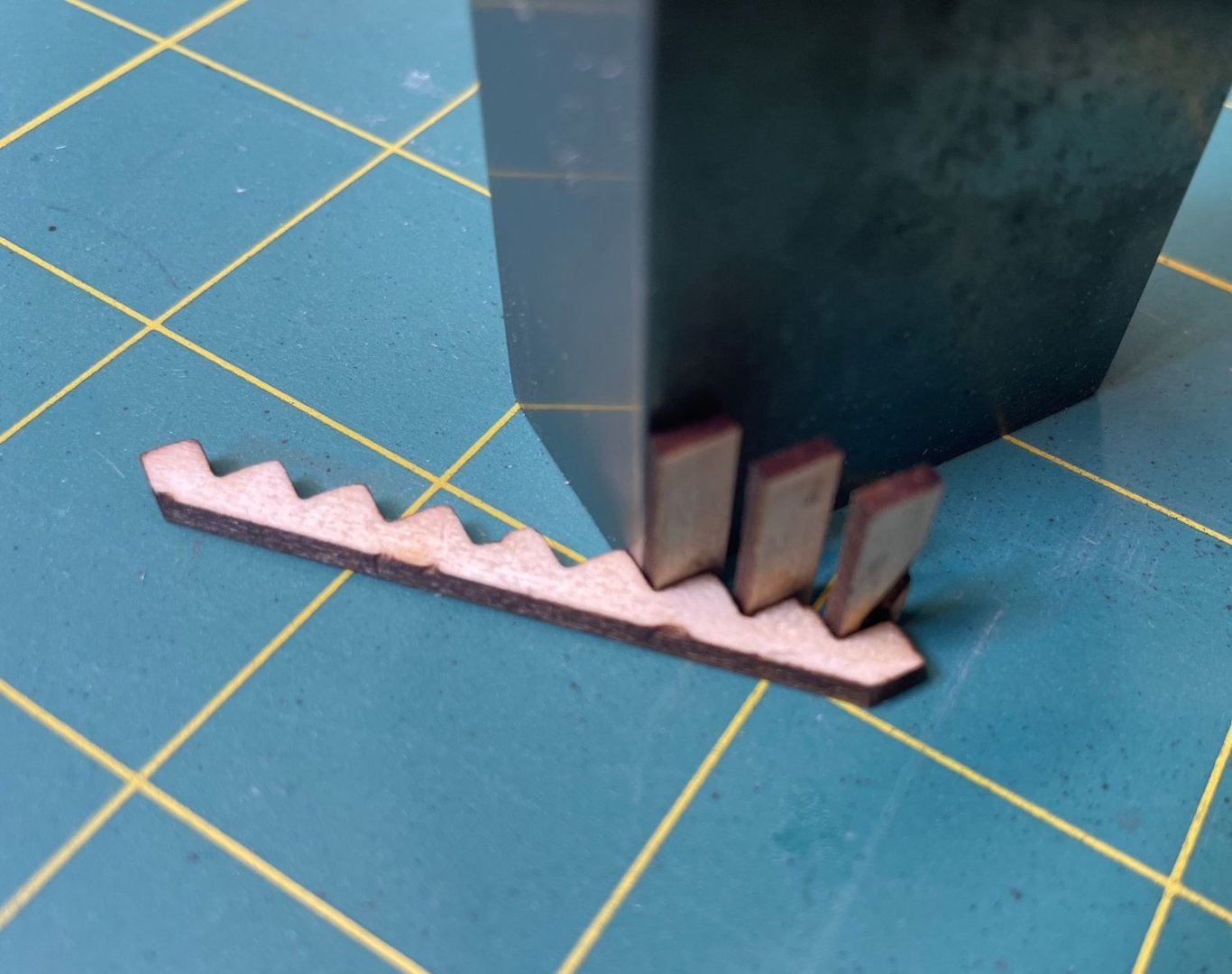
The forward steps were built and added to the main deckhouse. I took pictures of the started construction, but forgot to snap some of it going in.
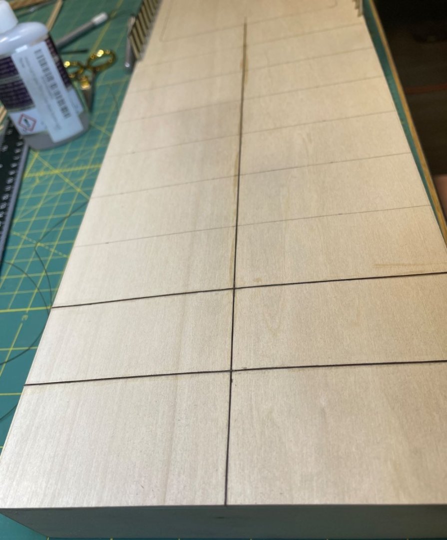
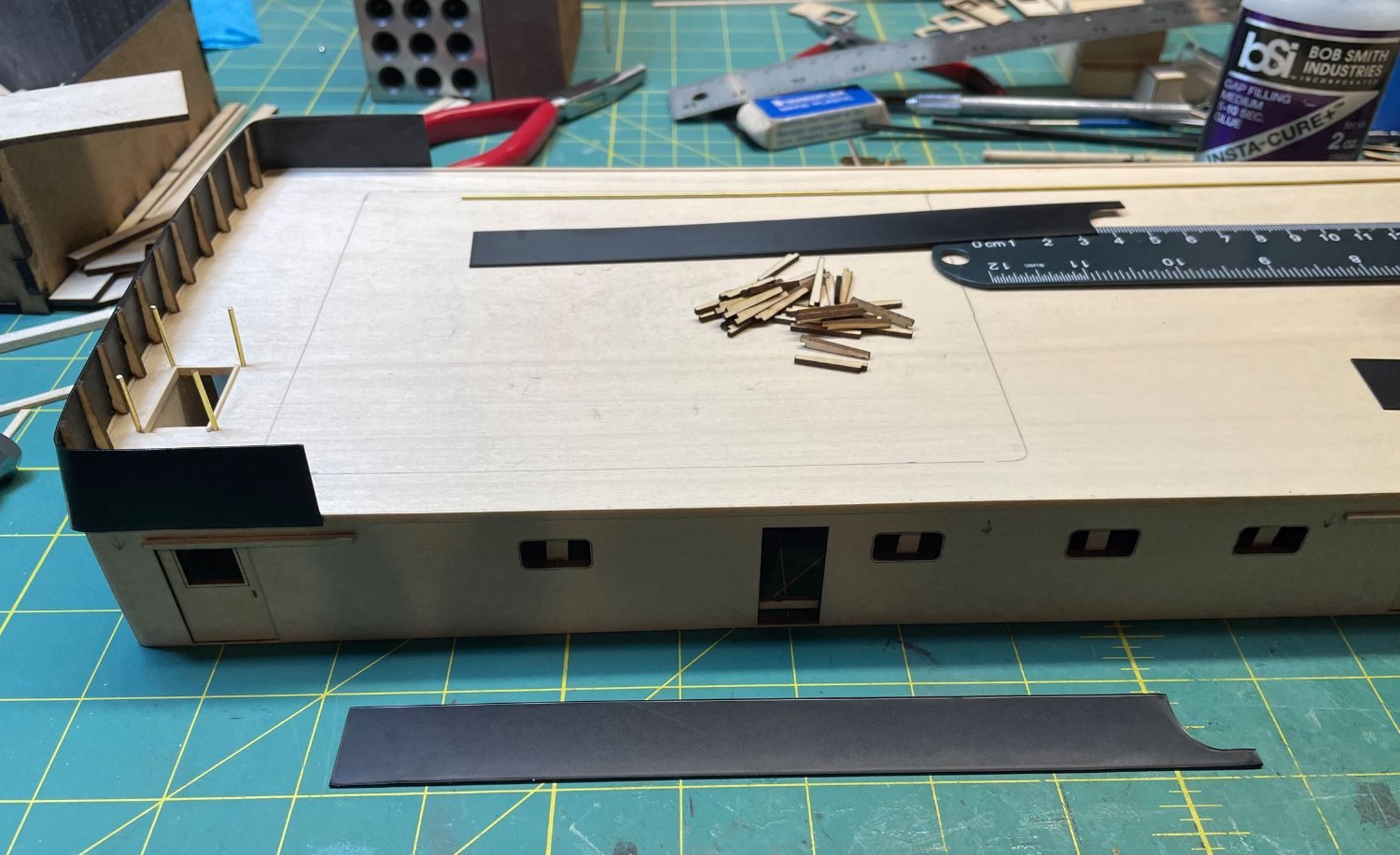
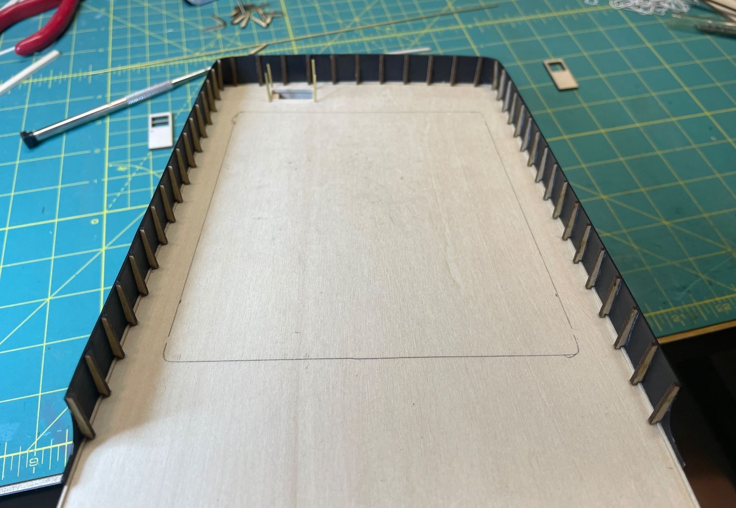
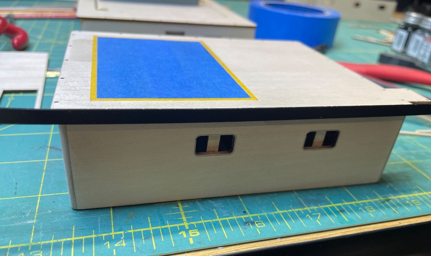
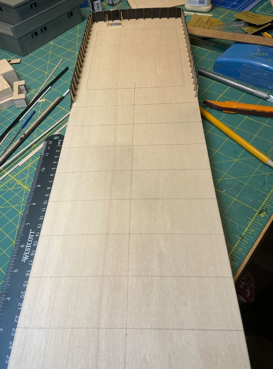
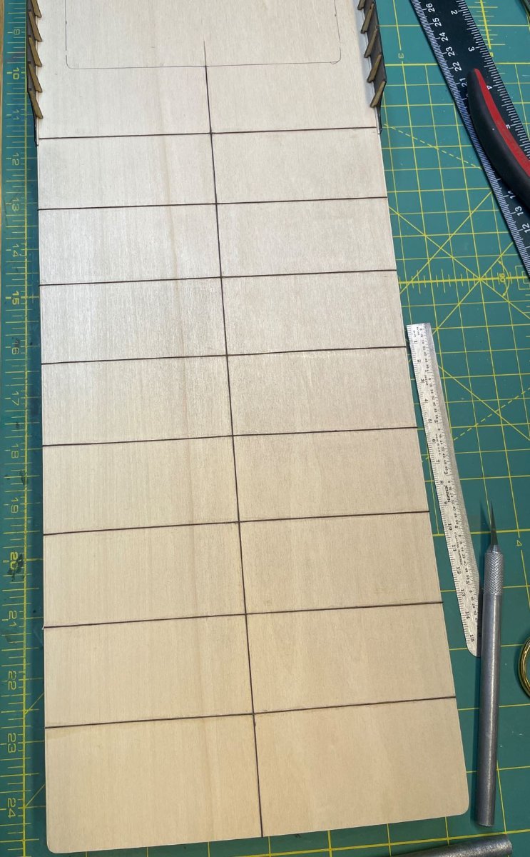
I wanted to add a bit of detail to the topside of the main deck. As you can see the weld lines of the steel panels is pretty visible on the next photo. I felt that since this is pretty open area I should go ahead and add this detail.

I started by marking off the panels where the welds should be.

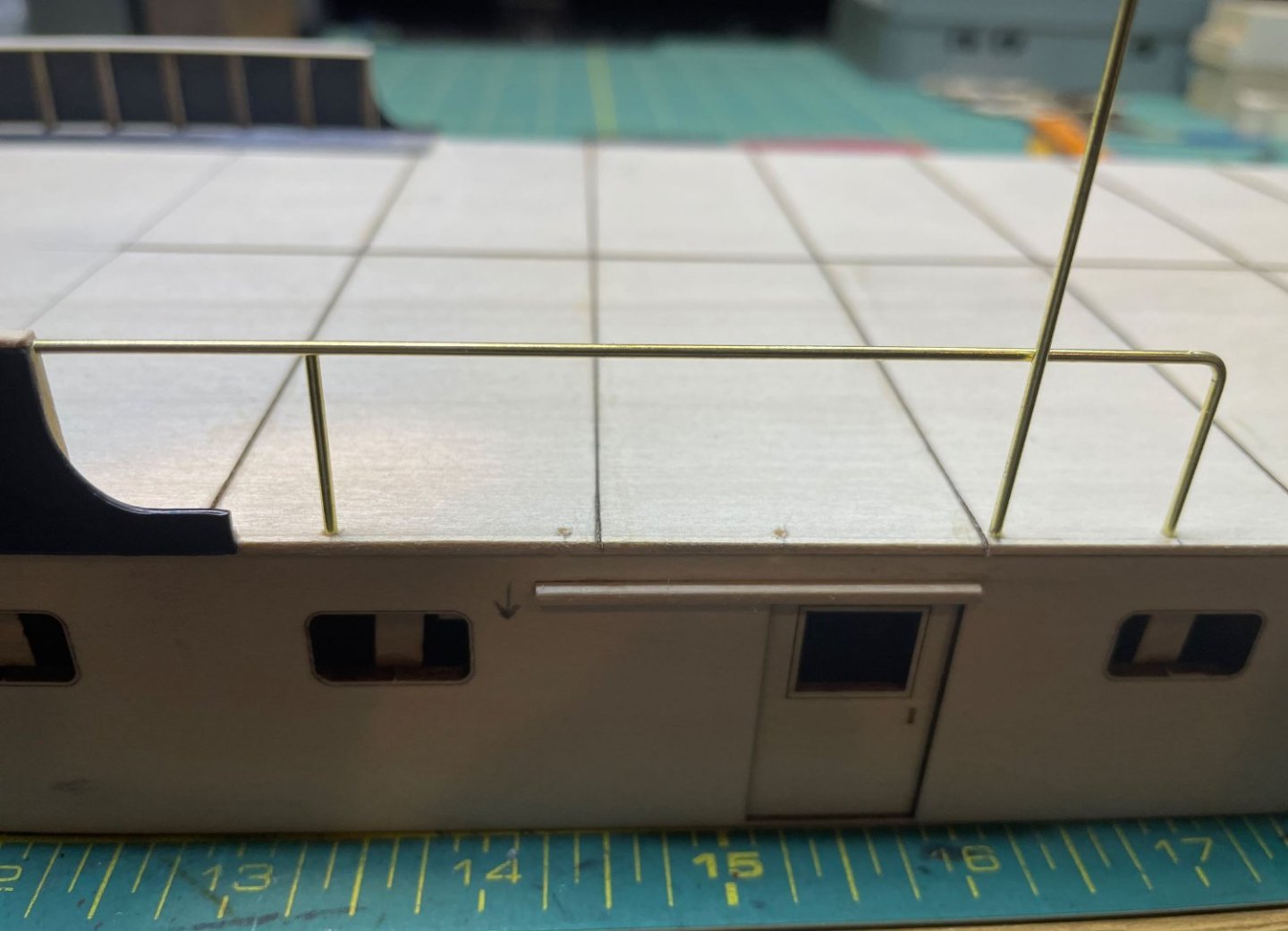
Then I took some small thread and glued it down along the lines. This should provide a nice profile of the welds on the deck once everything is painted up. At least that's the theory, we'll see how it works out.

Then it was time to tackle on of the features that I have been dreading. The railings. Personally I feel the same way about railings and ladders as some people feel about rigging.
So here we go.
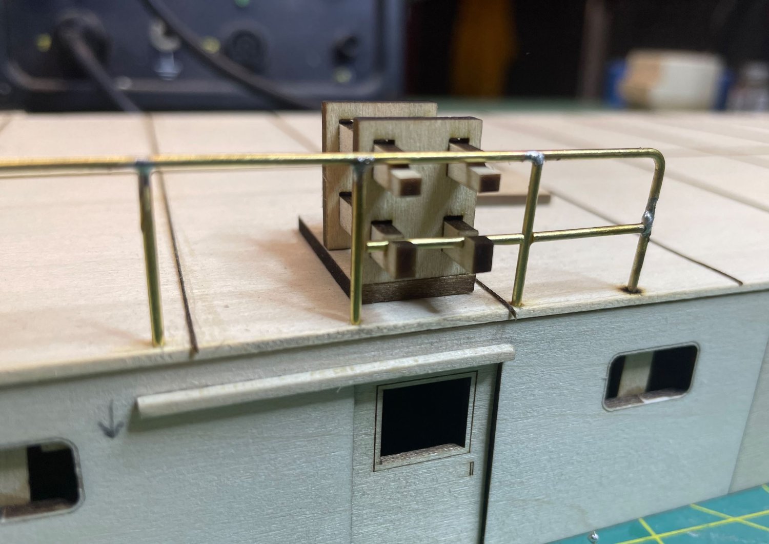
I figured that brass rod would be the perfect thing to build the railings out of. Its sturdy, easy to bend and cut. So I started with the portside main deckhouse railing. I cut and shaped the top rail and the stanchions.
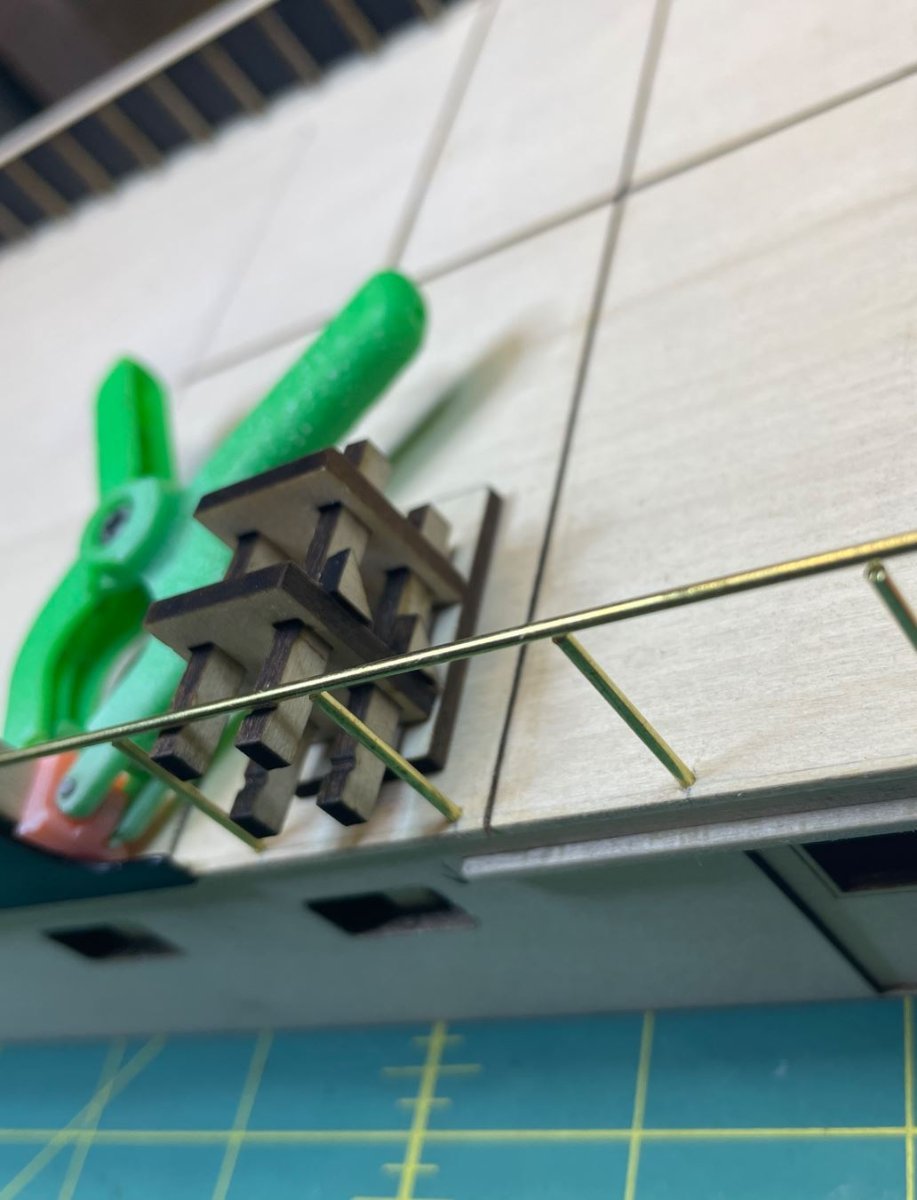
As I was working on this I was trying to figure out how I was going to hold the second rail pieces in place while I soldered the joints. So I drafted up a quick drawing of a jig that would help hold the cross pieces steady and level.
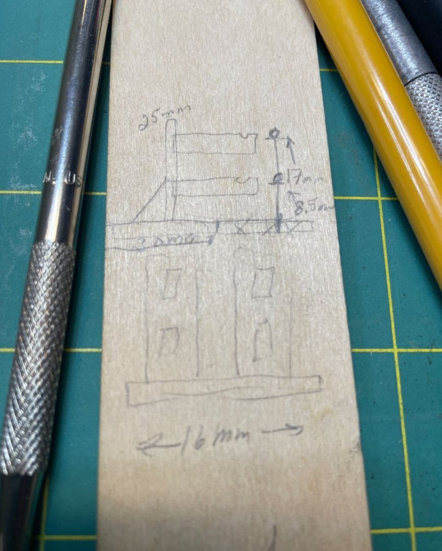
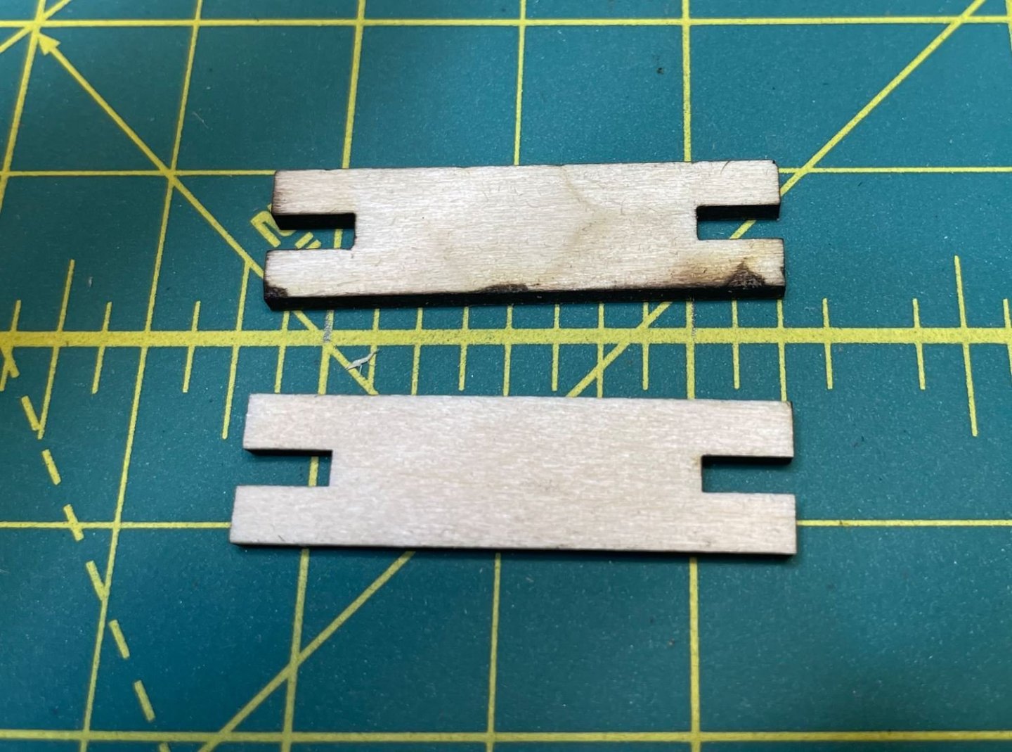
I measures out and drew up the pieces on the computer, then cut them out.

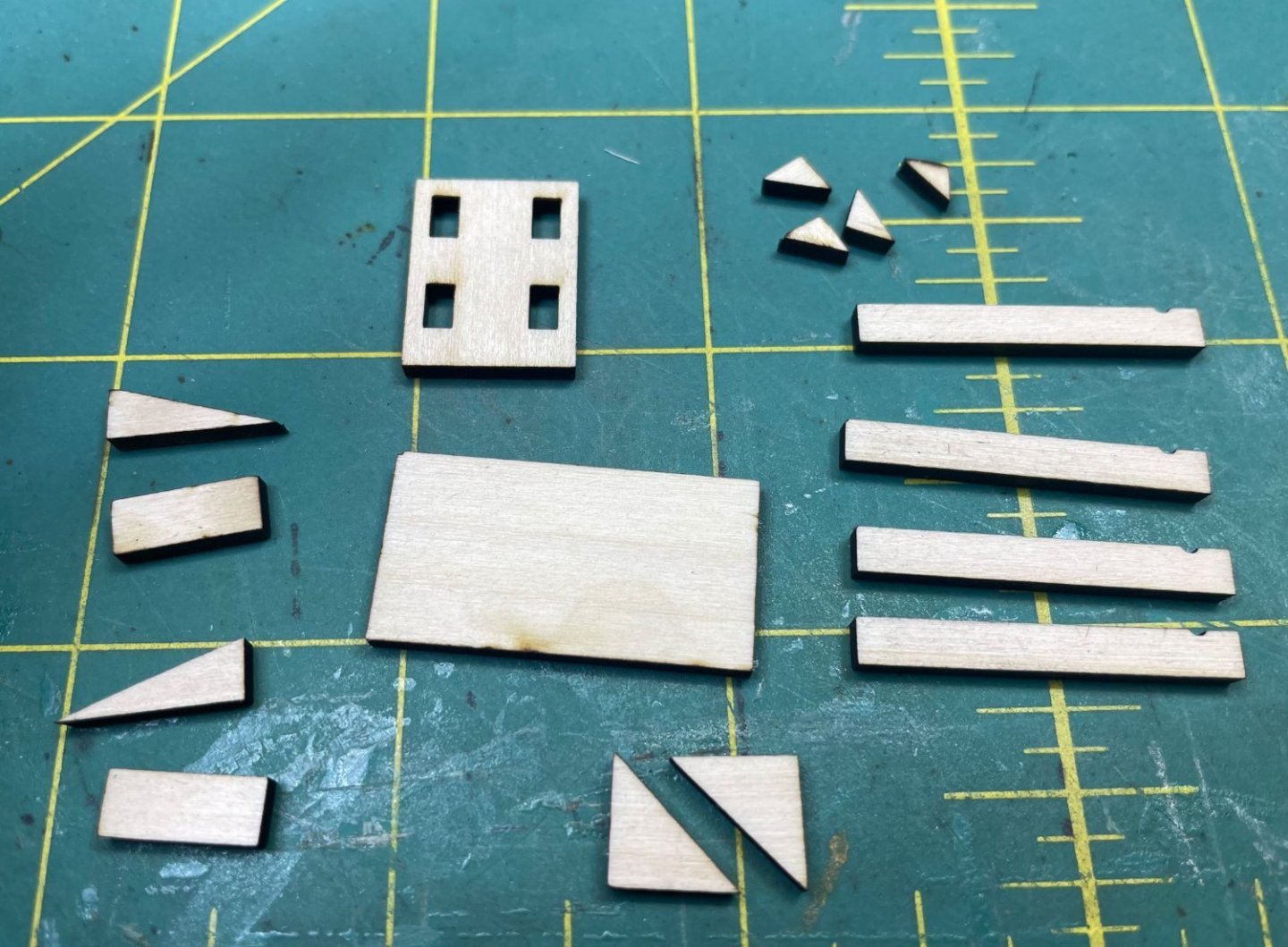
Assembled the pieces for the jig.
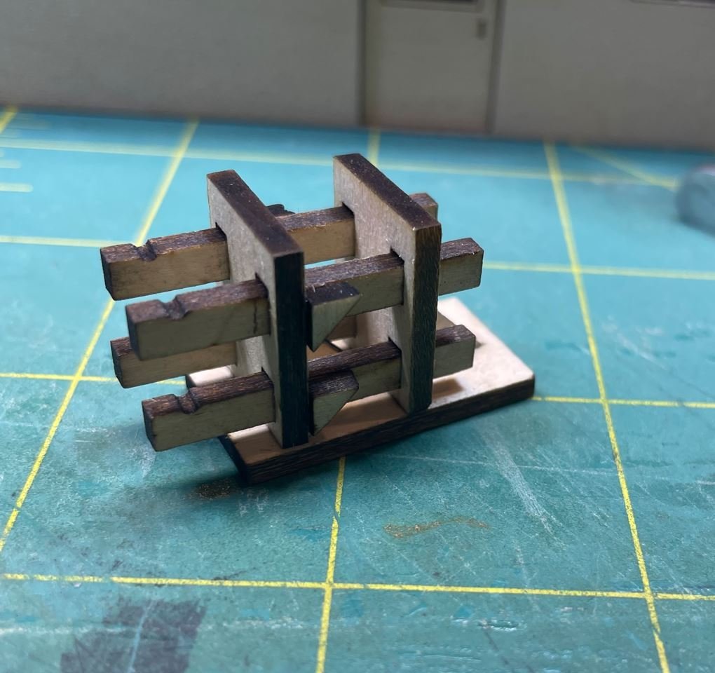
Then gave it a try.
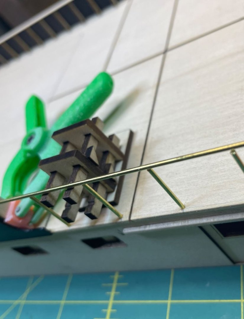
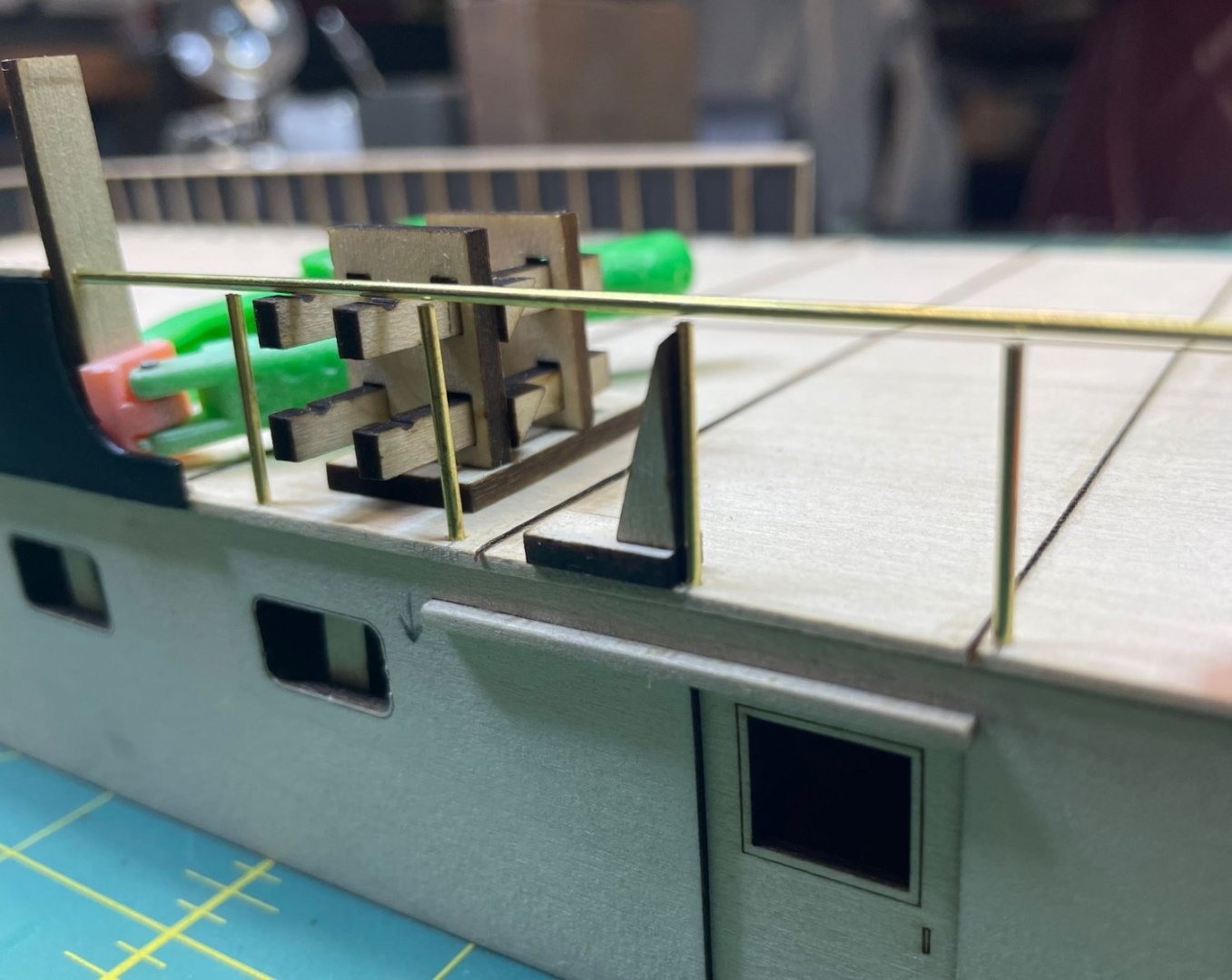
Everything work as it should, with one exception. My soldering skills stink. I tried several times to get the joints straight and to get the solder to pull in correctly, but I'm not sure If I had the iron too hot or too cold, but it just wasn't working for me. I even tried using the solderless adhesive, designed for brass and copper.

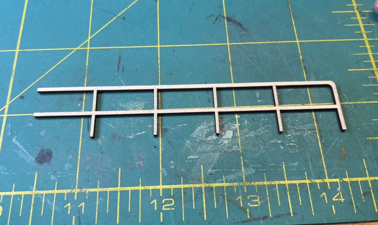
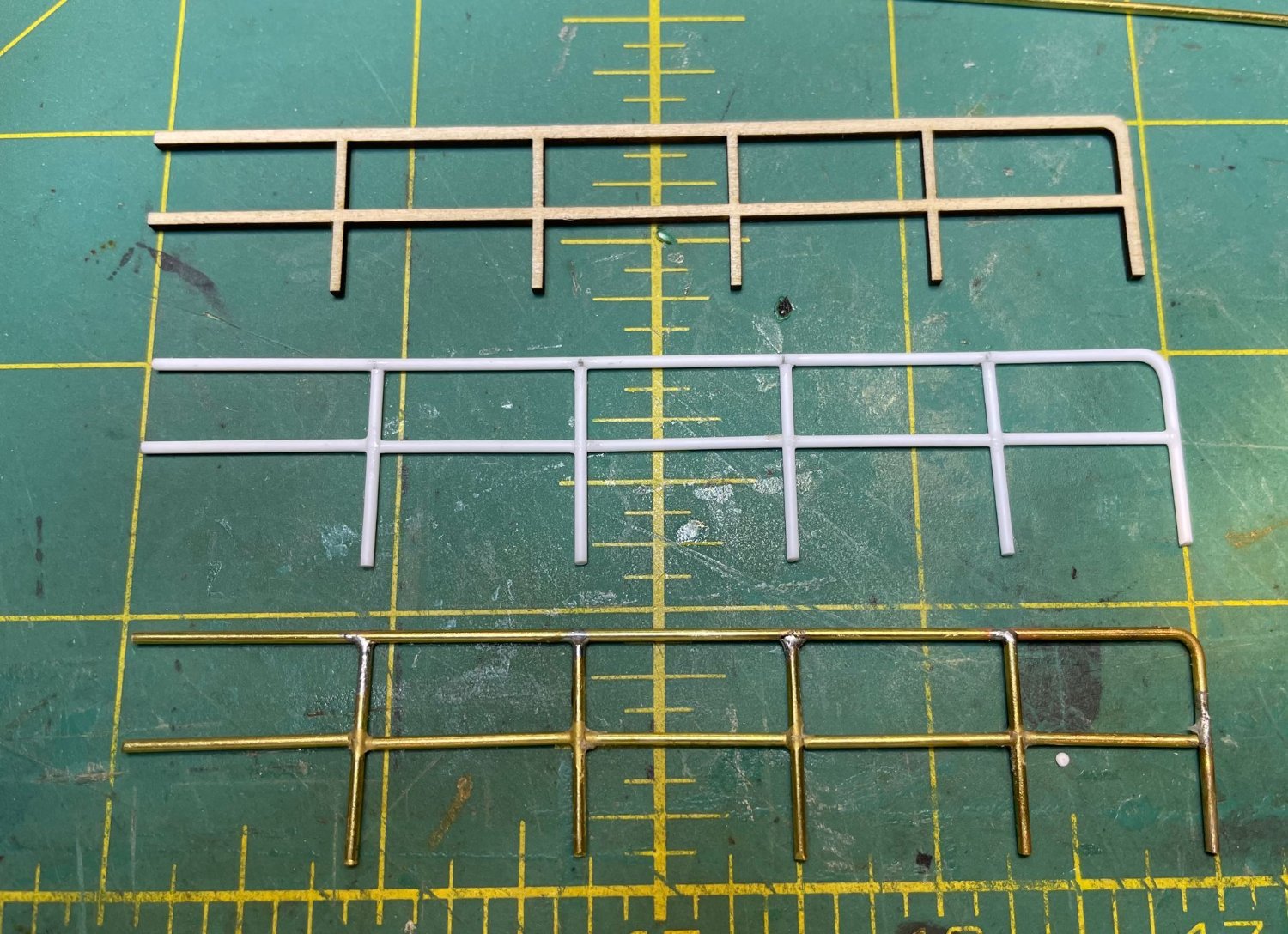
So it was on to my next option. I tried cutting the railing out of basswood. These made perfect railings, but then I ran into another obstacle. Now I have to sand all the rails to get them rounded. Definitely not worth the trouble of having to sand each and every pipe to get it round, not to mention taking care not to snap the raining in half along the grain.
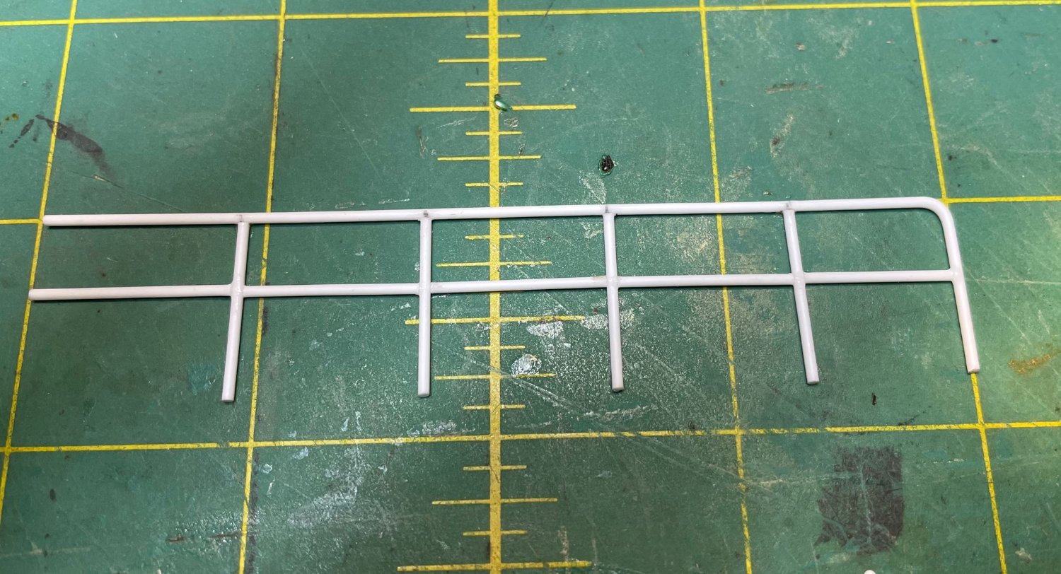
Attempt number three. Why not try making the railings from styrene rods? Styrene is easy to bend and cut and can be held together with CA. No soldering involved.

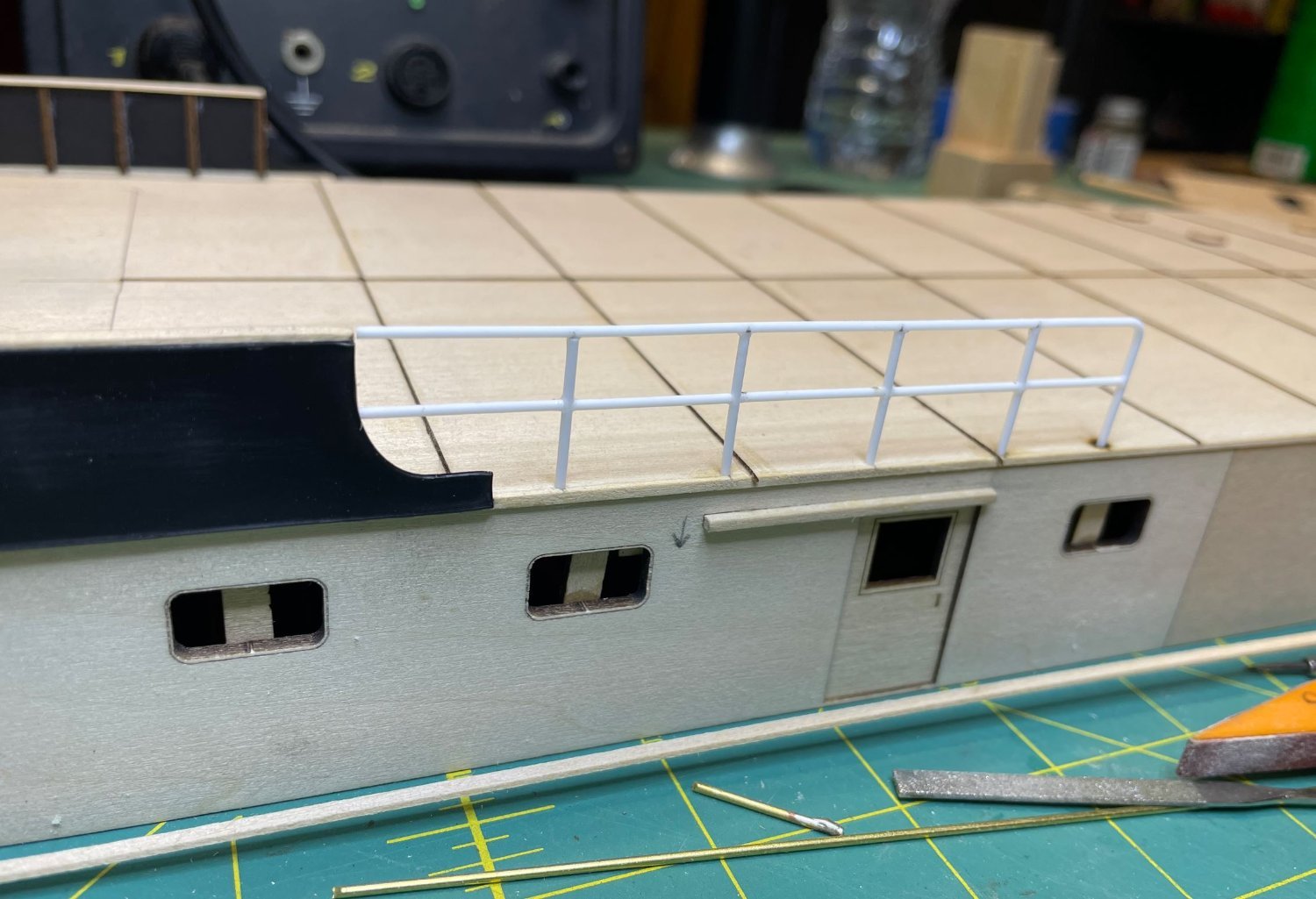
I'm thinking that I like this route better,

And the three attempts at my first railings.

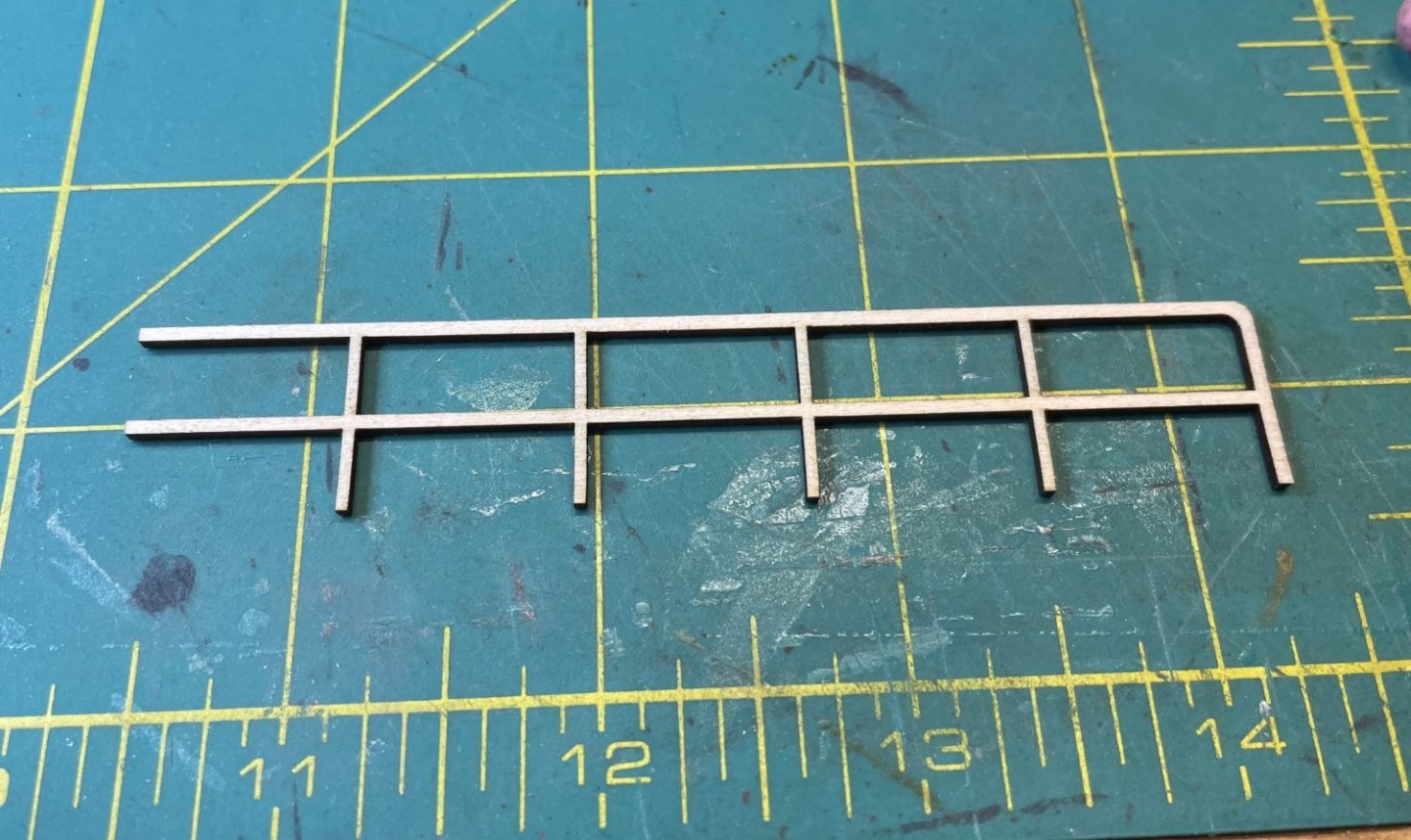
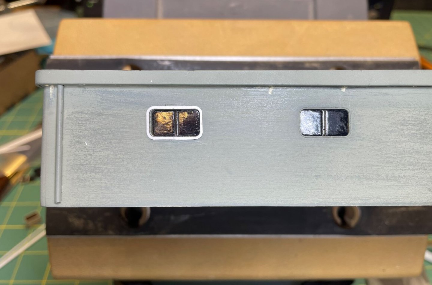
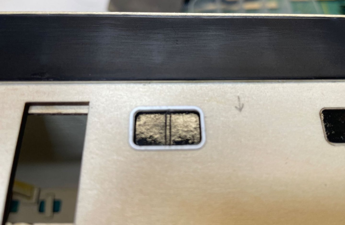
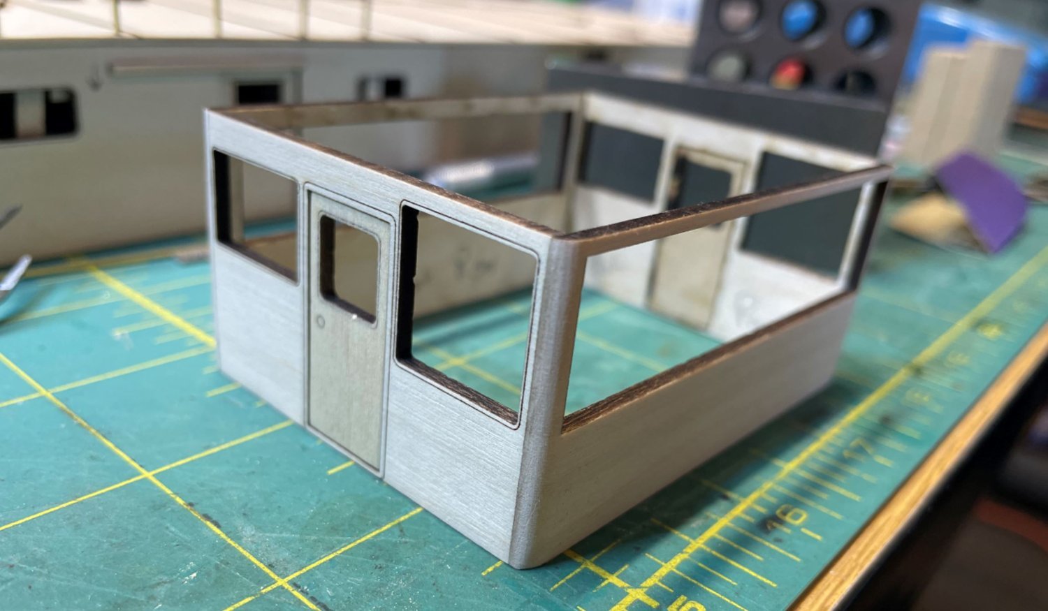
I decided to take a break for the railings for a bit and focus my attention elsewhere. To give the windows some depth and detail, I cut some framing from some heavy card stock and applied them to the outsides of the windows. Once painted up they will and a nice little level of detail to the walls.
I wanted to finish up on the deck structures so I could get them all painted up and get a good Idea of what the boat was going to look like. So I worked on the pilothouse top. Again, I drew up the pieces and cut them out.
Got them assembled. I used some of my leftover risers from the main deck to get the slope of the roof.
I couldn't figure out how I was going to get the sloped sides of the roof. There are several compounding angles that would very difficult to cut out and shape. The outside edges are sloped a good bit and curve around with the corners as well as the top sloping backwards to shed the rainwater off.

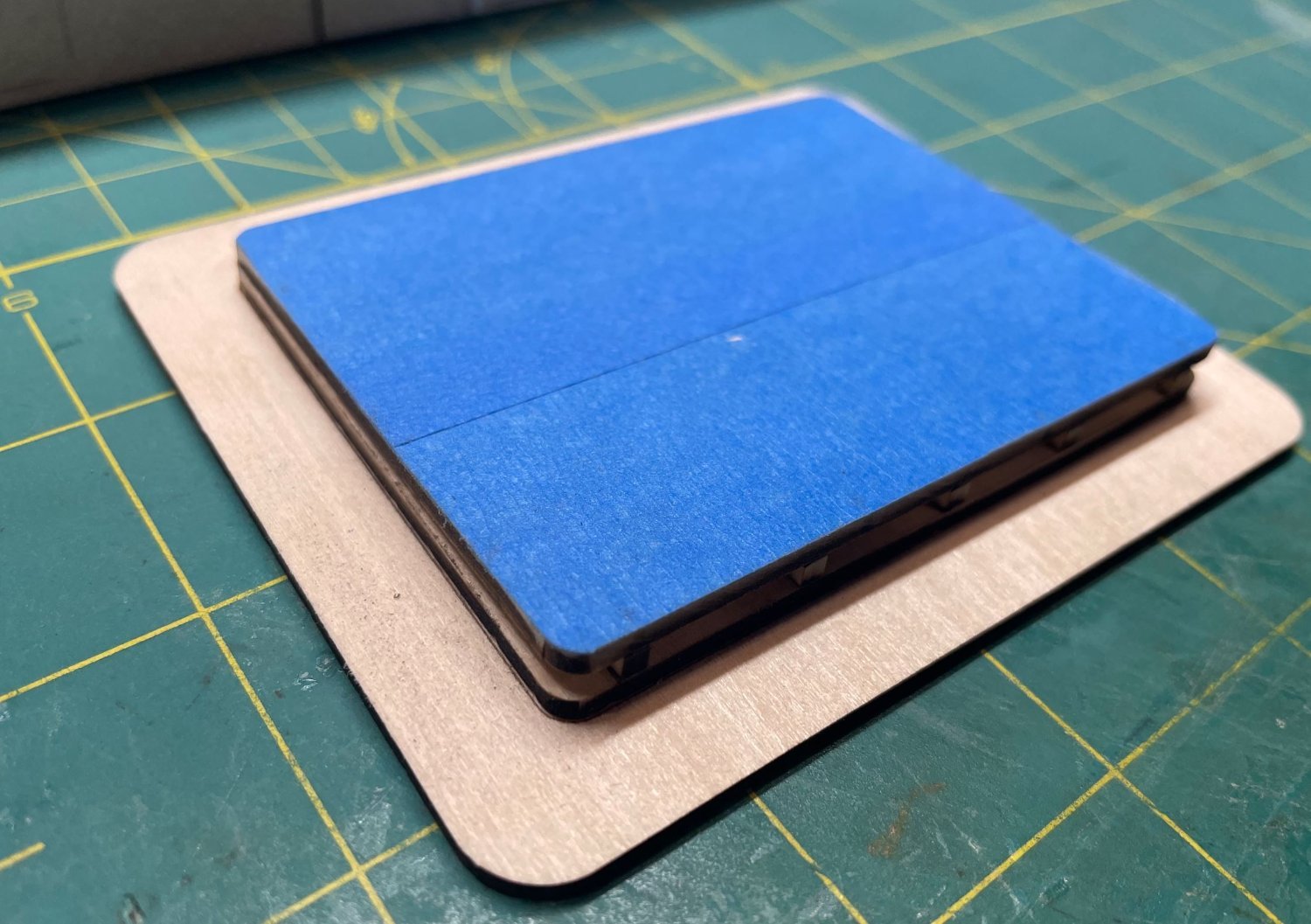
So after scratching a bald spot on my head, pondering this quandary, I finally came up with a solution. I taped the top off to protect the stanchion holes from getting filled in.

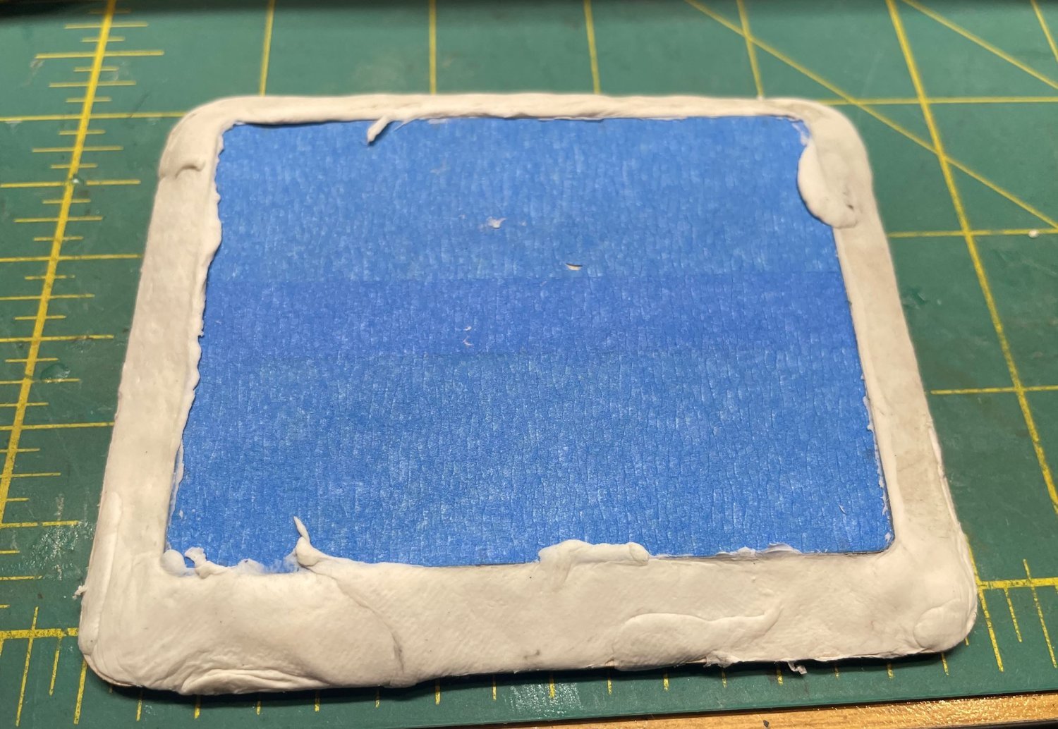
and with some air dry putty that I had on hand, I figured I could shape the outer slope and sand it to shape once it had dried.

Well another failed attempt. I didn't take into consideration that the moisture content of the putty would cause the assembly to warp. I tried setting some heavy weights on top of it for a few days, but I couldn't get the warp out of it. So, I ran another set of pieces and glued them all together and this time I used body filler instead of putty. That worked better with no warpage. Of course in my frustration I failed to take pictures of the body filler assembly.
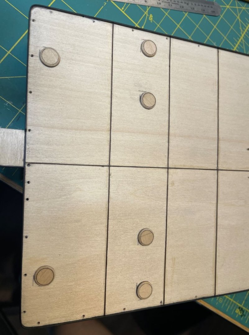
While the body filler was drying I worked on more of the main deckhouse details and installed some of the manhole covers.
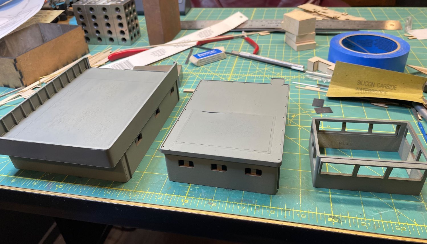
Finally after a good sanding and a shot of primer on the whole assembly, this is where I am at.
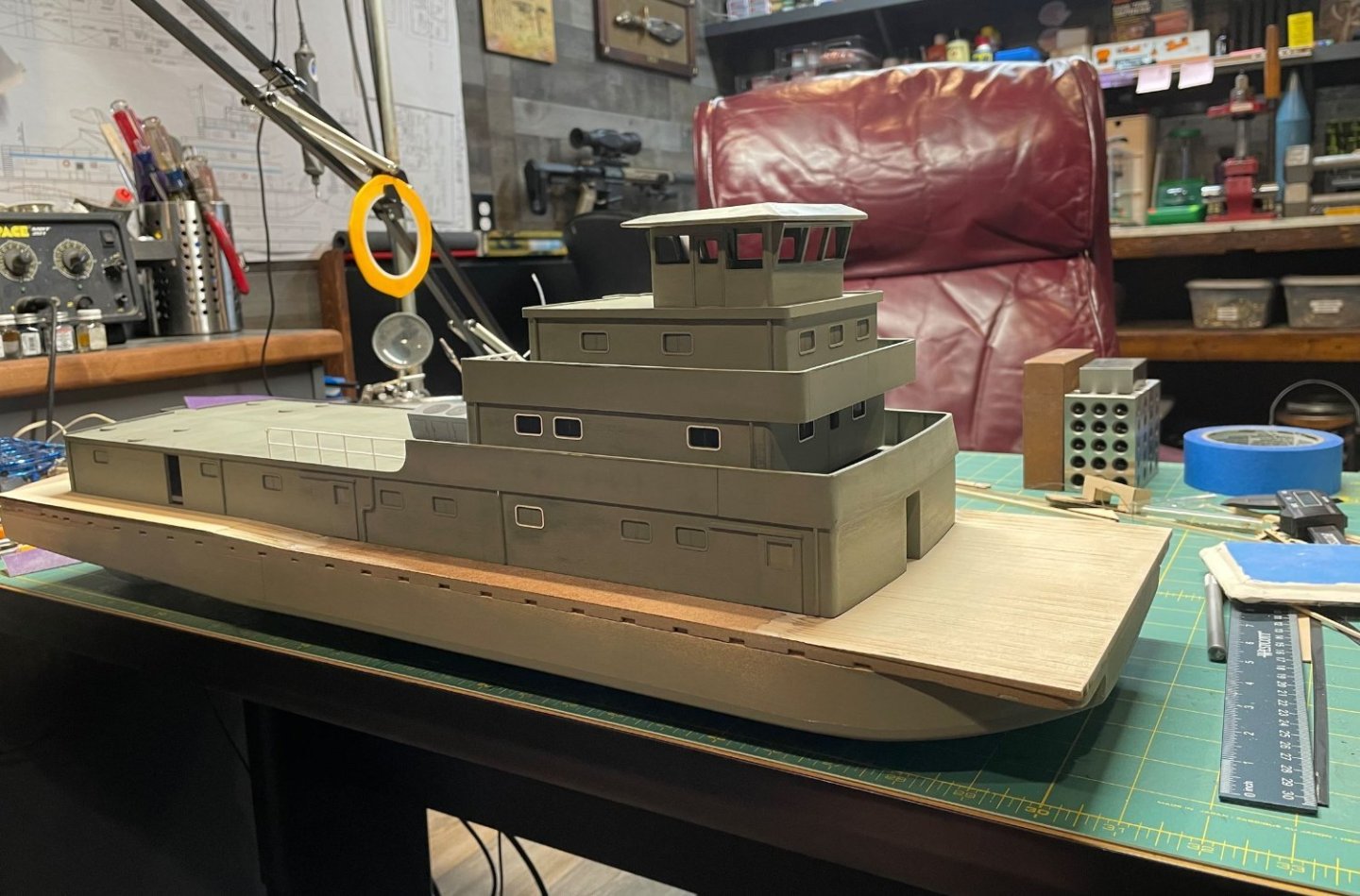
It's all starting to take shape. Upcoming work, I need to get the deckhouses painted up white and work on the hull. I want to get the props, Kort nozzles and rudders in place and the hull painted up so I can get it mounted to it's base. Those will be some updates for my next installment.
Thank you all for stopping by!
-Brian
-
Beautiful work Eberhard!
Your straps have given me an excellent idea. I have been struggling with my build on how to make my fire hoses. If I “borrow” the technique you used for your boat straps, I may just be able to disguise them as hoses and lay them in their racks.
-Brian
- davec, Tony Hunt, FriedClams and 2 others
-
5
-
-
Stunning work gentlemen, absolutely stunning! I sure hope that everything works out with the museum, I will make a trip to see this build first hand when it’s done.
-Brian
- mtaylor, Canute, Keith Black and 1 other
-
4
-
Very interesting topic Eric. I remember a couple of times seeing ice flows on the Mississippi in Baton Rouge. For the northern folk that’s not a strange occurrence, but for south Louisiana, it’s a rarity. People would flock to the levee to watch the ice drifting downstream. By the way, at the time of this writing we are getting that freezing rain here in North Texas. Should provide for some slick roads in the morning. Y’all be safe up there.
-Brian
-
Beautiful work, as always Keith! Now the real fun begins. Not sure if I mentioned this or now before, but rigging is one of my favorite tasks. Something about it just brings me joy seeing all the lines come together on a ship. Of course snagging them while I work and almost dragging the boat off the bench, tends to quell some of that joy, as well as bring out a few expletives, but it’s all part of it. Looking forward to seeing the shroud progress.
-Brian
- Glen McGuire, FriedClams, Dave_E and 3 others
-
5
-
1
-
Just catching up Eric, and you have definitely posed a good question. My initial thought was the coal could have been stored on the deck in front of the firebox as stated before. When first looking at the photo of the wreck, I thought that maybe the reason that it is not seen was because they cleared it off before the photo was taken. Then I noticed that the fires are still stoked, due to the smoke coming from the stacks, so that shot that theory down. I do like the idea that sacks of coal were used and just dumped out on the deck as they were used.
Not sure if it was common practice, but is it possible that there are coal bunkers actually in the deck itself that go down into the hold slightly? I’m thinking something like a sloped trough that would allow ease of shoveling, but far enough down that wouldn’t be noticeable in any of the photos? Just thinking out loud.
Good idea reinforcing the posts with wire. On several occasions I’ve had to beef up these delicate connections with wire or trenails. Definitely gives piece of mind to it’s stability. I also love the “grittiness” you add to your builds with the high traffic area wear. Adds to the realism and gives the boats life.
-Brian
-
Scrolling through these builds, enjoying the photos and commentary and learning new and old techniques of the progress is only part the entertainment that I get from this forum. The sideline conversation and banter is the added bonus that keeps me glued to the builds and coming back for more.
-Brian
- FriedClams, Keith Black, AJohnson and 4 others
-
7
-
2 hours ago, wefalck said:
I only had a quick look at their Web-site, but wondered how the machine handles fumes? They say that once can cut acrylic glass several millimetres thick, which would generate quite a bit of not-so-healthy fumes. The same would apply for cutting polystyrene.
The machine has an exhaust fan on the back with a duct that you can vent outside. They also have an air purifier attachment that you can purchase separately that filters the exhaust fumes and smoke. For now, I just have the duct attached to the back and when I run the tool, I just pop the window open and drop the duct outside. A little crude, but it works for now until I can get around to building a permanent solution for it.
-Brian
-
5 hours ago, KeithAug said:
You make it sound very easy Brian. But I am sure I could screw it up. However I am very jealous. Now how to buy one secretly and convince the wife it's just a barbecue.😀
It really is pretty easy to use Keith, and there are numerous tutorials out there that give step by step instructions. I bet if you set the laser to the highest setting and slow passes on engrave you could cook with it. Now to just convince your wife of that, it could be called a multi functional BBQ.😆
-Brian
- Roger Pellett, KeithAug, Keith Black and 1 other
-
4
-
Beautiful Keith! I have often found myself in the quandary of getting the inside work done before the shrouds or visa-versa.
Doing the internal work without the shrouds is so much easier to access, but I’ve always thought that once the inside work was done and the shrouds added later that the tension of installing the shrouds would cause a sag on the inner lines. So, I’ve always worked from the outside in, praying to the ship gods that i didn’t snag a line and dump the whole thing in the floor. Oh the trials of model shipbuilding. 😁
-Brian
-
4 hours ago, Cathead said:
I didn’t realize you could DIY kit-like parts like that.
It wasn’t until I started making the parts that I realized that many of the kit manufacturers probably use similar equipment to make their kits. Albeit their machines are likely a lot more pricey and robust than this one.
-Brian
- Keith Black, Ryland Craze, mtaylor and 3 others
-
6
-
1 hour ago, Roger Pellett said:
what sort of software does thing use?
It runs on a free downloadable proprietary software called XTool Creative Space (XCS) which is real easy to use plus there are several tutorials out there to help with the more complicated features. Another program that interfaces well with it and a lot of XTool owners use is Lightburn, but that’s a aftermarket software that costs, but it does offer many more features than XCS. You can also create a .svg file in any supported software and manipulate it in the XCS program. I managed to learn a good bit in a few short days.
-Brian
-
Hello again,
Time has a way of getting away from us, and I didn't realize that it has been over a month since my last update. With the holidays, I needed two of me to keep up with everything that I was doing. I have made some progress on the the Caroline though, and I figure it about time to get something posted.
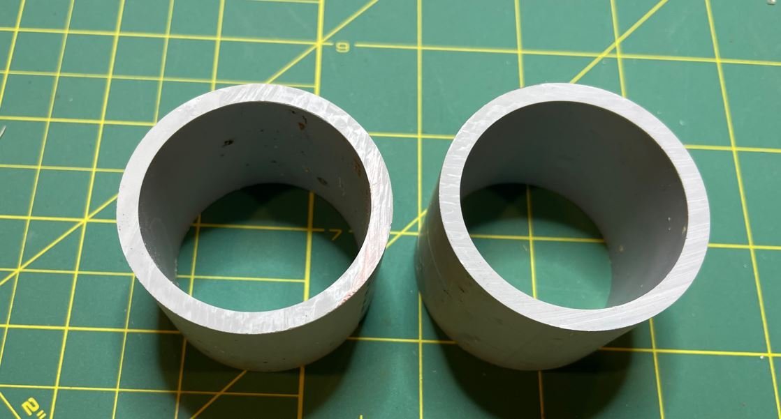
So before the holiday's hit I managed to work on the Kort Nozzles. For these I found that 1 1/2" plastic conduit was the perfect diameter for these, and saved me a ton of time having to shape these out of styrene. Ok, I admit the size wasn't exactly perfect, they were .75mm larger than the correct scale, but I figured that was close enough, and by the time I finished shaping them I would be close enough. Besides these will be on the bottom and not fully seen.
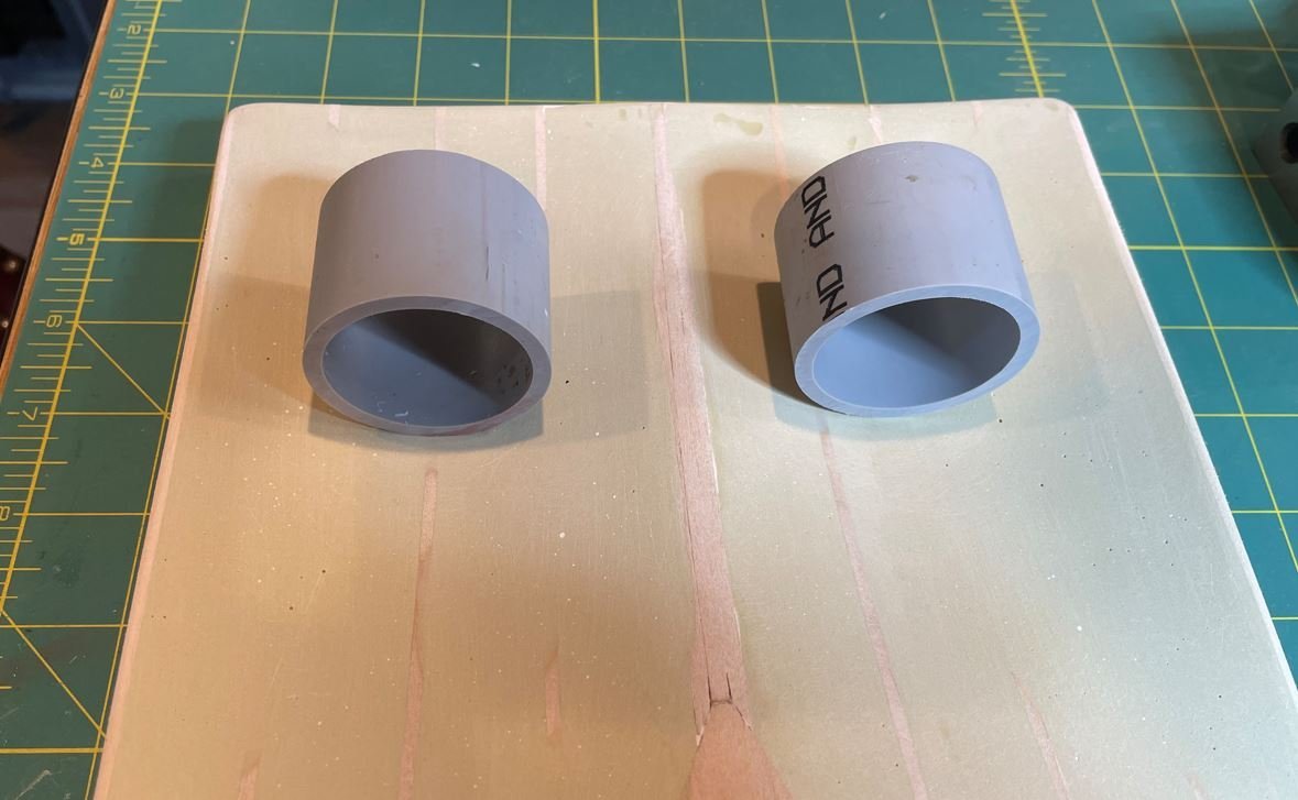
Placement on the hull in there approximate location.
I put the nozzles on my drum sander and used that as an arbor to sand them into shape with a sanding block and files. I forgot to take photos of the process, my phone was in my hobby room and I was too lazy to go get it. But anyway, this was the first nozzle roughly shaped, compared to the original pipe.
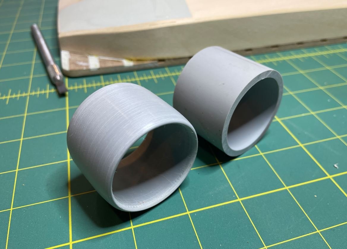
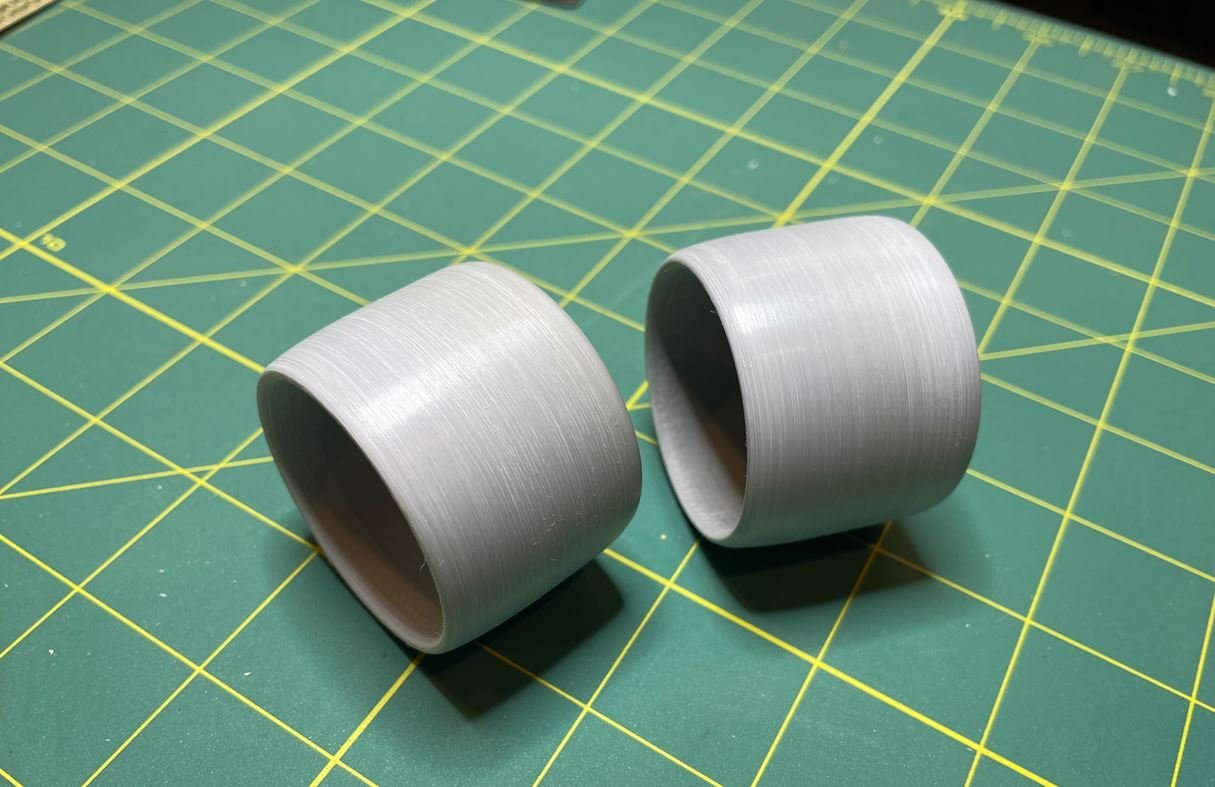
Both nozzles with their general shape. I still need to get them smoothed out a little more and add a few details for them, but I like what I have so far.
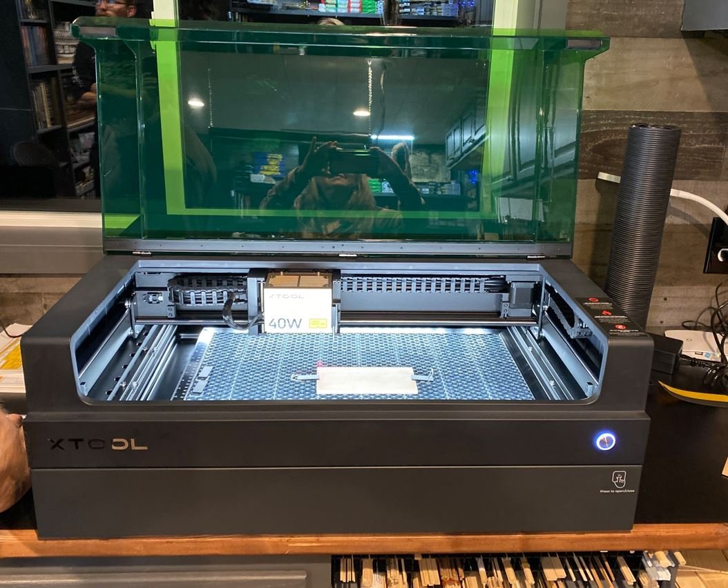
Then the Christmas holiday hit and Santa was very good to me. The Admiral and I decided that we needed a new toy to support our craft and shipbuilding hobby and we decided to invest in a laser engraver. After extensive research we decided that an XTool S1 would be worth the investment, so we bit the bullet and purchased one.
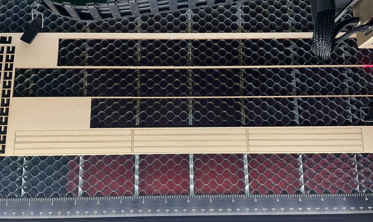
So I spent a few days tinkering around with the engraver and it's software, making small, little simple projects just to get the feel for it, then it was time to see what it could really do. So why not try it out on the Caroline. Here I am working on the walls for the first two decks. Pretty easy since they are somewhat square.
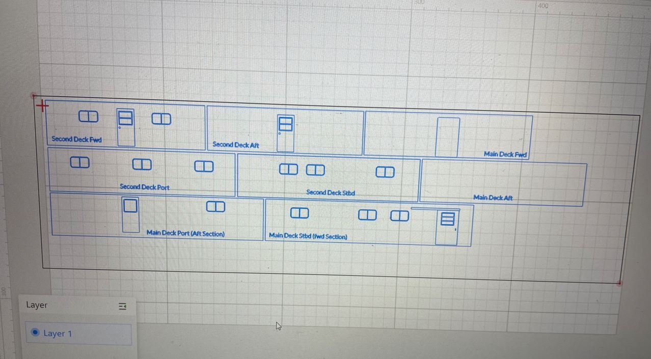
Then it was time to see what this baby would do.
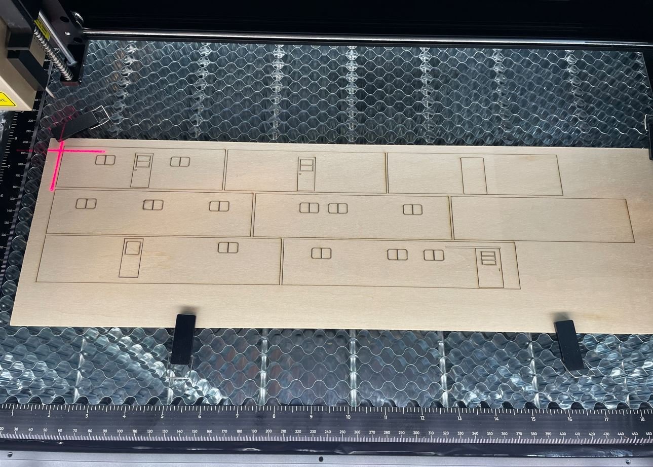
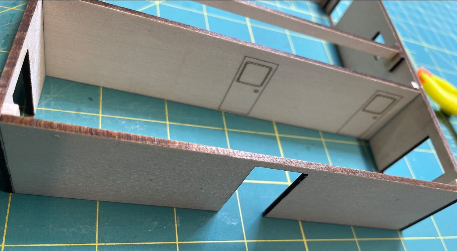
Couldn't ask for better results. So I played around with the windows a bit, using different thicknesses of wood to give them more dimension and depth and engraving the window frames, as well as some of the door features.
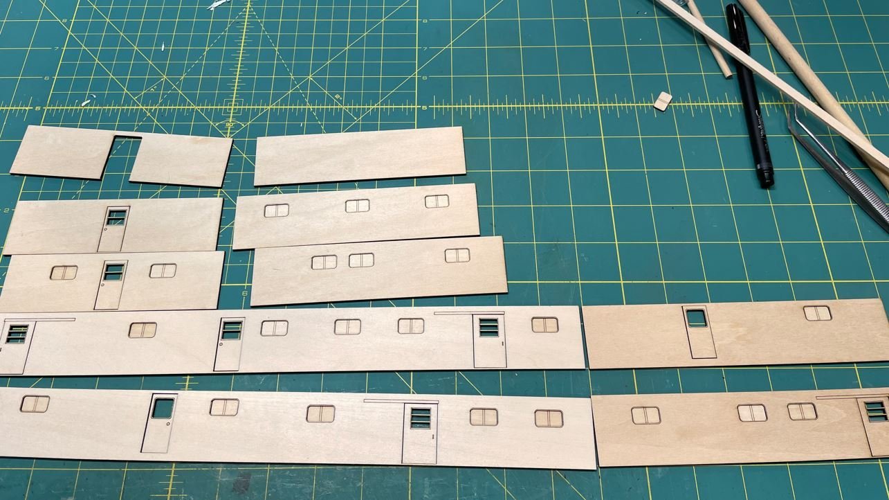
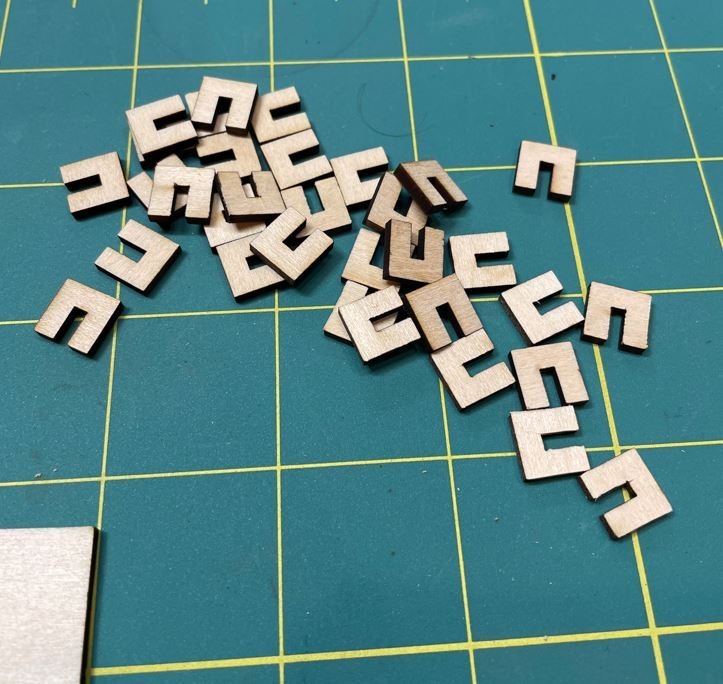
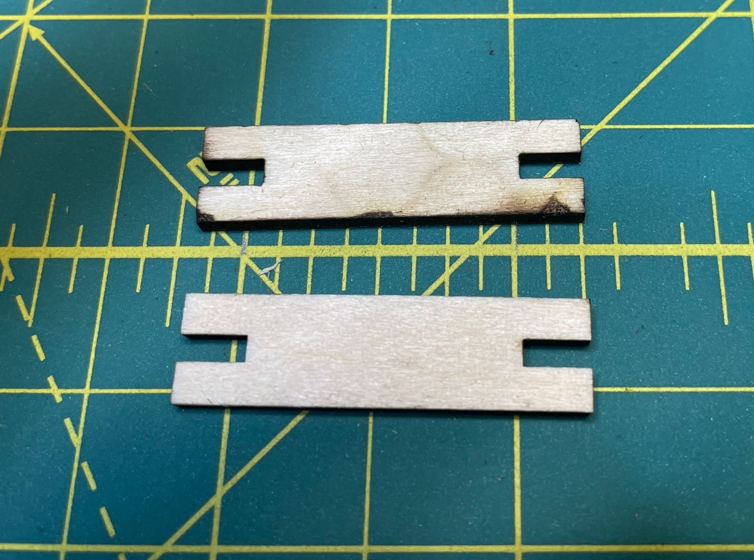
So to help with some of the wall structure I drew up little brackets to help support the wall braces and cut them out as well as the braces.
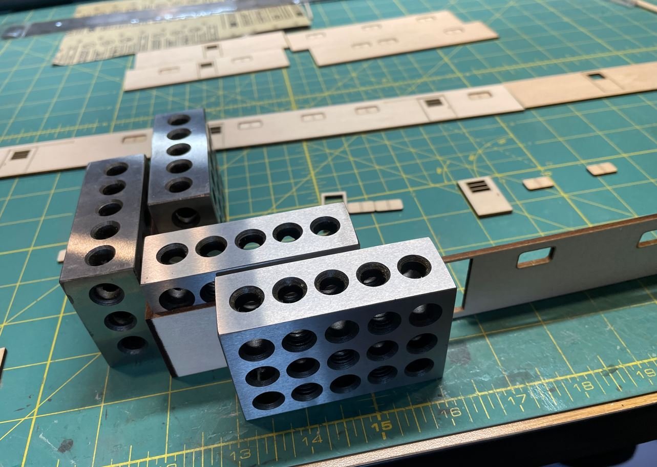
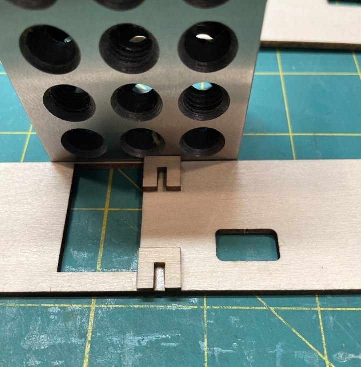
Then it was time to give it all a test fit. I'm thinking I am going to really like this tool.
I do realize that this is somewhat turning a scratch build into a kit build, and hopefully no one thinks that this is cheating. But hey, aren't most kits started from a scratch built model?
I've got more to come, but I just found out the hard way that CA has a shelf life, and after first opening my current bottle two years ago, it's adhesion is just not what it used to be. So for now I'll work on some of the other deck walls and get them designed while I am waiting on a new bottle of CA to arrive.
That will do it for this update. Thank you all for stopping by and the kind comments.
-Brian
-
13 hours ago, Roger Pellett said:
This allowed me to put tension on the wire to endure round, uniform rings.
I hope you don’t mind me stealing this method Roger. I usually just wrap the wire around a small drill bit with finger strength for rings. The end results like you said were not quite round, but I found they worked at the time. Never thought of putting tension on the wire. Still learning.
-Brian
- FriedClams, Canute, mtaylor and 5 others
-
8
-
Happy New Year Keith!
-Brian
- Glen McGuire, AJohnson, Keith Black and 5 others
-
7
-
1
-
Oh wow! That photo really shows the scale of just how small this boat really was. Now I understand how she got by with just one boiler.
-Brian
- Keith Black, mtaylor, Canute and 3 others
-
6
-
I was thinking it was called the flume, but my knowledge of steamboat terminology is somewhat limited. However, I do like Eberhards description of “thingy between boiler and stacks”. A technical term that works well 😁.
It’s surprising that she only had one boiler, I would think that she would have had at least two given the power needed to propel her upriver. However, thinking about it, steam locomotives got by with just one boiler and they seemed to function quite well.
-Brian
- Ras Ambrioso, Jack12477, mtaylor and 4 others
-
7


Caroline N by mbp521 - Scale 1:64 - Mississippi River Towboat
in - Build logs for subjects built 1901 - Present Day
Posted
Thank you Yves for the kind comments. I am using an XTool S1 laser engraver and the proprietary software that comes with it called XTool Creative Space. I have to say, it has opened up a whole new world of making model ship parts.
Funny that you say that. The guy that I am building this boat for read my last update and sent me a text message laughing about that very detail. My response was, "I don't miss details"")
-Brian