


gjdale
-
Posts
4,894 -
Joined
-
Last visited
Content Type
Profiles
Forums
Gallery
Events
Everything posted by gjdale
-
 Sorry to hear that Mark - sounds like something I would do! The paint solution sounds like a good plan.
- 505 replies
-
- 4
-

-
- vanguard models
- Sphinx
- (and 1 more)
-
Do you need to be “fiddling” with all five or six sections at once, or can you focus on one section at a time? I’d be leaning towards the white PVA myself but you can get this in different set times. If you go for one of the slower setting ones, you should be okay.
-
Love it Bug - my sentiments exactly! I’ve lost count of the number of times I’ve referenced back to Danny’s logs to re-read how he did something. That said, I’ve referenced your work on more than one occasion, so don’t sell yourself short. 😊
- 419 replies
-
- 3
-
-
- Victory Models
- Pegasus
- (and 2 more)
-
Nice to see you back with a build log Andy. Looks great so far - had a chuckle over the doggy incident!
-
I assume you are talking 6:00am Brisbane time Richard, so 7:00 am for the rest of the east coast…. Works for me. 😊
-
At the end of the day, they are just numbers so it doesn’t really matter which you use. Where it does make a difference is in tooling - for example a mill or lathe, which will have their lead screws calibrated in either one system or the other (your choice on purchase). In that case, you may need to convert from one measurement system to the other, but then again, if you have a digital readout it again just becomes a matter of dialling in the the right number.
-
Thanks Bob, It’s more difficult to describe than to do. Once you can visualise the completed joint and keep that straight in your head, marking the joint extremities on the second half of the joint is just a matter of being slow and methodical, and triple checking everything before cutting. If the marking out is correct, the joint will be a pretty good fit straight off the cut/pare. If the marking out isn’t accurate, you can end up chasing your tail for quite some time trying to get a good fit. In another log, Druxey suggested practising this joint on some scrap wood first. Good advice - my scrap wood just happened to be additional actual stock…….😉
-
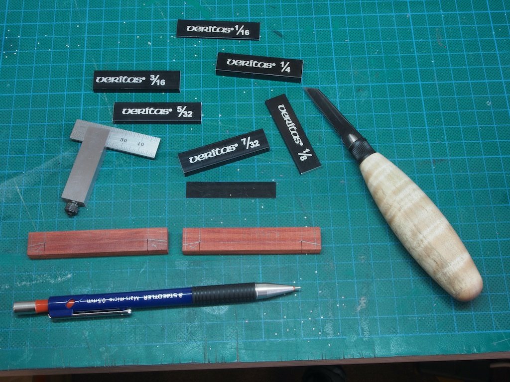
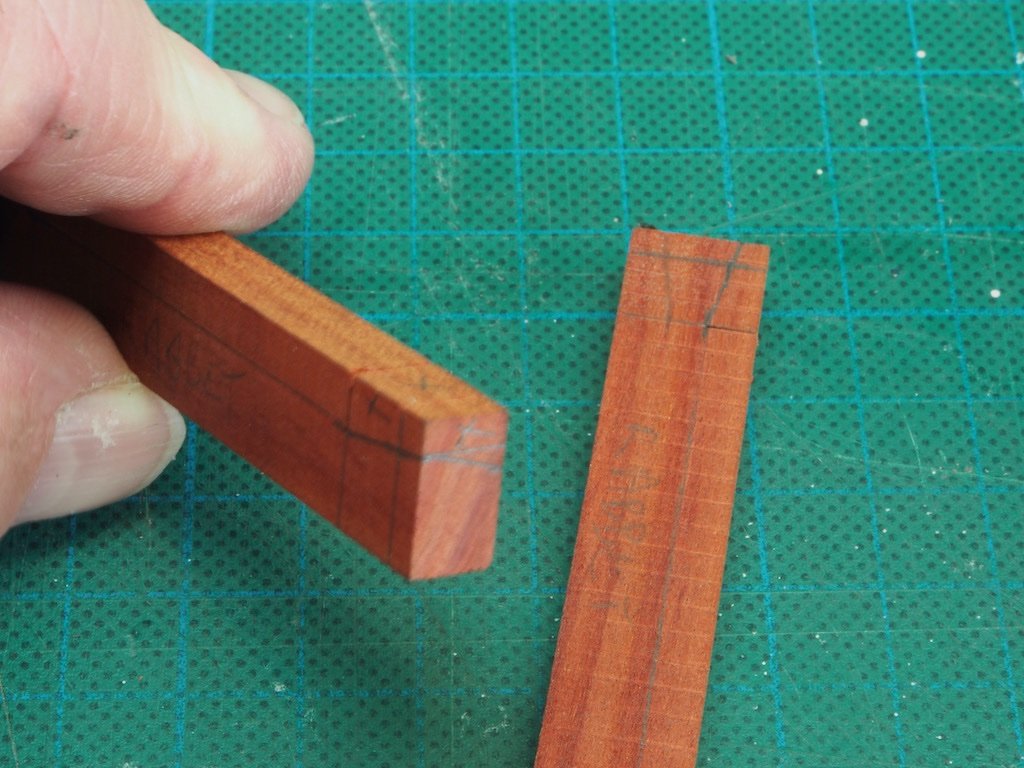
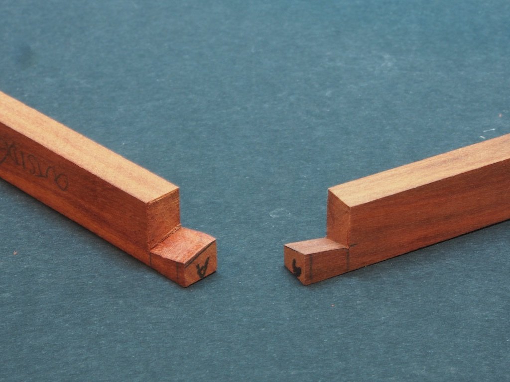
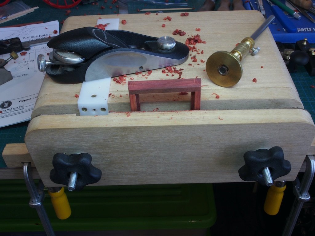
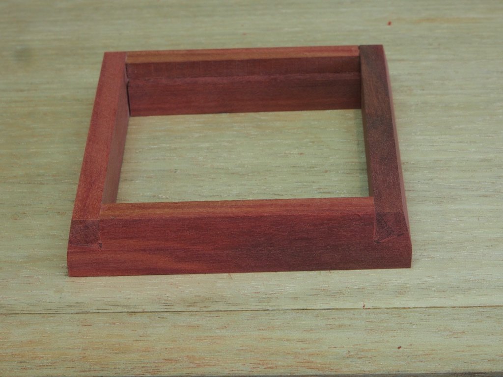
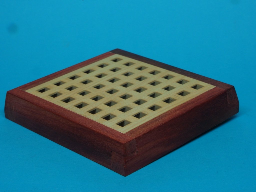
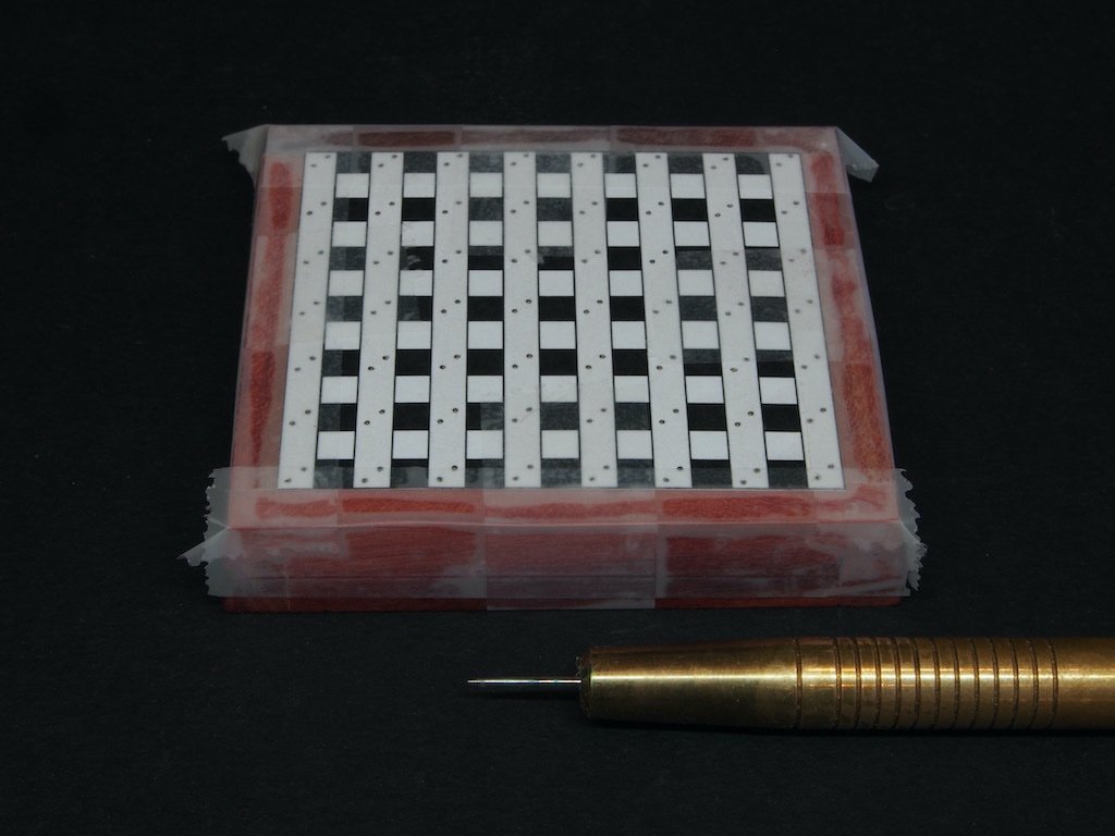
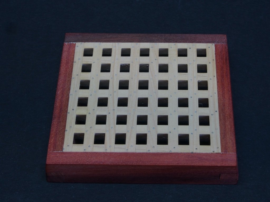
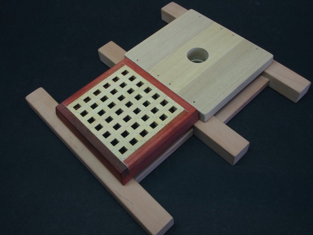
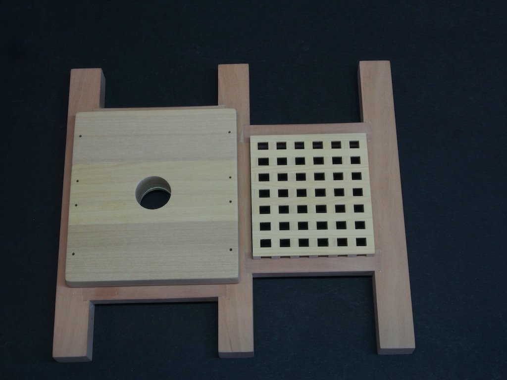
It seems that time has gotten away from me again! Thanks Bob and Tom for your kind comments and for all of the "likes". On with the show! Hatch (P/N 102) This is the trickiest part of the build to date. It is made so by the joinery for the hatch, with the Coamings and Head Ledges being joined by “tailed half-lap joints”. This means that the joints are angled in two planes. It took some time to get my head around these joints, and after a few failed attempts I had to walk away for a few days before trying again. Then I got distracted with other tasks around the house and suddenly it was a few weeks before I got back to it. The key to success here is accurate marking out. To make the first half of the joint, measurements were taken from the drawings. I found my set of set-up blocks most useful for this task, along with a marking knife. The pencil was only used to go over the knife lines to improve their visibility. The second half of the joint must be marked directly from the first half, and this is the most difficult part. The method I finally succeeded with was to mark a pin prick with the marking knife to correspond with all four extremities of the first half of the joint. Then it was a case of using a ruler and the knife to “join the dots”. Cutting the joints was achieved with a razor saw and a full size, very sharp chisel. By keeping away from the marked lines initially, I was then able to pare to the line with the chisel and make any minor adjustments for a good fit. I got so engrossed in this process that I forgot to take any progress shots. Here is an example though of the joints cut, showing the angles in two planes. This picture is actaully of some “rejects”. Once I had satisfactory joints in all four corners, they were glued up and the rabbet pieces cut to size and fitted. The sides of the hatch are vertical for the bottom half, and then taper inwards by one-half inch (actual size). Rather than using a sanding block to achieve this, I used a marking gauge to define the extremities of the taper and then used a block plane to remove the excess material. I used my home-made mini Moxxon vise to hold the piece while I planed the sides, coming in from both ends to avoid breakout on the cross-grain joint. Here is the finished Hatch, ready for installation of the grating. The grating was then carefully adjusted for a snug fit. I found I needed to sand just the slightest amount off each side of the grating. It was then glued in place and the top surface sanded level with the hatch sides. I was contemplating how to mark out the positions for the fasteners, when it hit me that the answer was staring me in the face. I simply cut out the scale drawing of the grating and taped it over my grating. I then used my home-made needle point scribing tool to mark the positions. Once the pattern was removed, a pencil lead was twirled in the holes and the surface sanded lightly. And finally, here is an overview of progress to date: That completes all the “easy” part of this build. Next up we commence some lathe work with building of the Capstan body.
- 43 replies
-
- 11
-
-

-
I think you’ll find a HUGE interest in a POF kit Chuck. An offering of the quality you have produced with everything you have done so far will be head and shoulders above anything else available on the market today. Add to that your approach to building and documenting as you go (as in Winnie), and I think you will have a real winner on your hands.
- 1,784 replies
-
- 7
-
-
- winchelsea
- Syren Ship Model Company
- (and 1 more)
-
Pat, Doesn’t solve your issue with email, but I’ve had good success buying my Sherline bits and pieces through Mike’s Tools in the US. Prices are good and service is prompt.
-
Well I’m certainly interested Richard - and for a change, I’m in the same time Zone as you (almost). 😊
-
Looks good Floyd. I look forward to seeing the results after tumbling.
-
Hard to believe those parts were created by the same machine! Well done Alan - your perseverance has certainly paid off.
- 460 replies
-
- 5
-
-
- Finished
- Flower-class
- (and 1 more)
-
Glad to hear you have found the source of your problems Alan, but not so glad to hear of the poor QC with material choice by the manufacturer. If the filament is that hard, maybe you should 3D print some replacements for the brass part!
- 460 replies
-
- 5
-
-
- Finished
- Flower-class
- (and 1 more)
-
Ducati 1299 by Moonbug - Pocher - 1/4 Scale
gjdale replied to Moonbug's topic in Completed non-ship models
Spot on Bug - not sorry at all. 😊 My wife likes the Pocher cars more than my ship models, so she suggested a special display cabinet for them in our dining room. I’m working on the design of this now. I’m being helped by a professional furniture maker with the design process - there appears to be a lot more to it than you might first think! When I finally get around to building it, I’ll post some pics. Expect to start construction around Xmas time-ish.- 25 replies
-
- 10
-
-
Ducati 1299 by Moonbug - Pocher - 1/4 Scale
gjdale replied to Moonbug's topic in Completed non-ship models
Nice model Bug. I still blame you for my own Pocher addiction. In addition to the Alfa Romeo Spider, I now have another three Pocher classic cars to build. And it’s all YOUR fault!!!!!!!! (Oh, did I say, thank you?) PS My wife has now commissioned me to build a display cabinet specifically for the Pocher cars…….- 25 replies
-
- 10
-
-
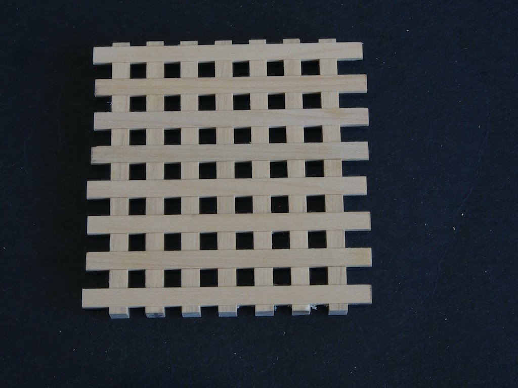
Two steps forward, one step back... When I measured what would be the final dimensions of my grating, I was disappointed to find that it was significantly out from the drawings and Toni’s dimensions. I think this is a classic example of cumulative error creep. There are 7 Ledges and 8 Battens involved here, so a miniscule dimensional error in either of these soon adds up. I think that a rounding error in the scaling and or conversion to metric might also have been at play. The net result was that I broke out the isopropyl alcohol and disassembled the grating. I then printed out a scale version of the drawing so that I could overlay the grating on this as I was building it up. The spacing for the Battens seemed fine – meaning that my milling of the notches in the Ledges was okay. I found that by adjusting the spacing between the Ledges by the tiniest amount would result in final dimensions of the right size. After playing around a bit, I found that by using my set-up blocks with a 4.5mm combination gave just the right spacing. Here is the final result in place on the deck beams. If you look really closely, you can see that the holes in the gratings are not exactly square, but I’m satisfied with the overall appearance. I’ve yet to add the simulated fastenings. In the picture below, you can also see that I’ve drilled the bolt holes in the Capstan Step. Now I’m ready to face the daunting prospect of the Hatch Coaming and it’s tricky angular joinery….
-
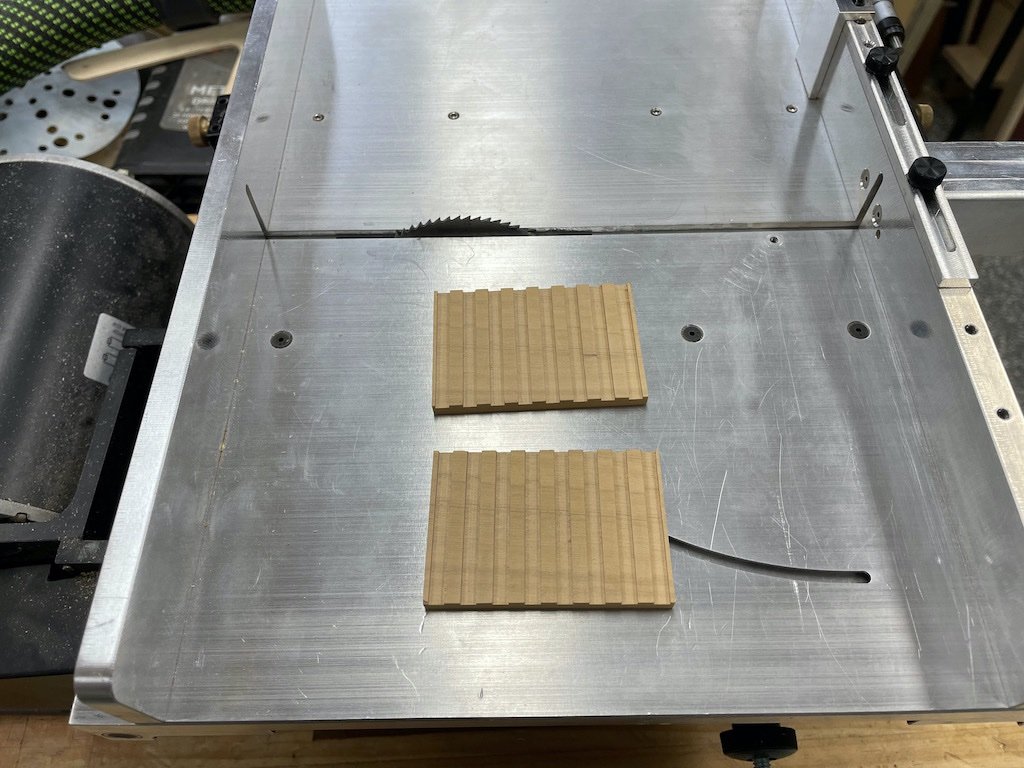
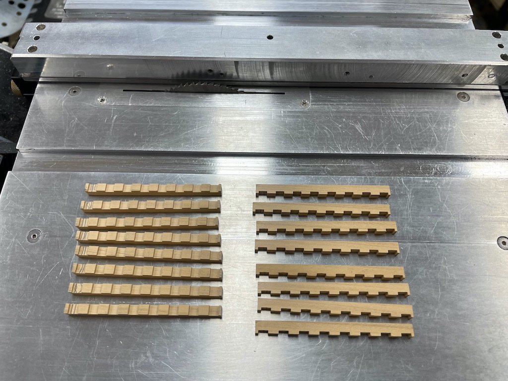
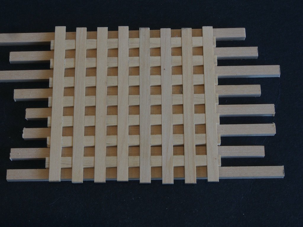
Grating (P/N 101) Although Toni instructs us to make the Hatch Coaming prior to making the grating, I decided to make the grating first and then adjust the size of the Hatch if necessary. I have never scratch built a grating before, so this was to be new territory for me. Toni provides instructions for two methods of making the Ledges (the part with the “teeth”). I chose to follow neither, so what follows is my own take on how to make them. The Battens (the part that fits into the “teeth” on the Ledges) work out at a scale 5/32” wide x 3/64” thick. This means that the rebate between the teeth, as well as the teeth themselves, must also be 5/32” if we are to achieve a square opening. Fortunately, I happen to have an end mill cutter of 5/32” diameter. Rather than cutting individual strips for the Ledges, then ganging them up to cut the rebates, then separating them again, I decided to cut the rebates into a single piece of stock that was wide enough for the individual Ledge strips to be ripped from later. The stock was also long enough for me to make enough for two sets of ledges. Prior to cutting the Ledges, I did one test cut in some scrap and then used this as a gauge to fine tune the width of the Battens that were ripped on the Byrnes saw from some 3/64” thick stock. The mill made short work of this task. By further happy coincidence, 5/32” converts to exactly 4.0mm, which made traversing the mill for each cut a lot easier. I am thankful to have the digital readout though – it made it much harder to stuff it up! I forgot to take some “in process” photos, but here is the result after milling (the rebates are 3/64” (1.2mm) deep). The milling left a little fuzz on the edge of the slots, which was easily cleaned up with a swipe of some 320 grit sandpaper. Here is the cleaned up piece with a batten inserted as a test fit. This piece was then cross-cut into two sections, each with enough slots for a complete grating. The main reason for doing this was to shorten the length to be ripped as I find that the longer the rip cut, the more likely that binding on the saw blade will occur. A piece of scrap was used to fine tune the fence setting, then the blocks were ripped into the individual ledge strips. There was sufficient width of stock to rip one spare Ledge from each block. Here are the final Ledges. While I had the fence set, I ripped some 3.0mm stock to the same width to use as spacers while assembling the grating. Once I was happy with the dry fit, the Battens were removed one at a time, a drop of glue placed in the rebate and the Batten returned. Once I’d glued all of the Battens, the spacers were removed in case any glue squeeze-out accidentally caught them. Once the glue has set, I’ll trim the edges on all sides and add the (simulated) fastenings. Next up, the Hatch Coaming...


-
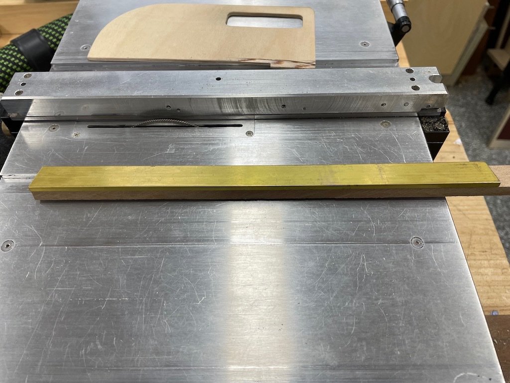
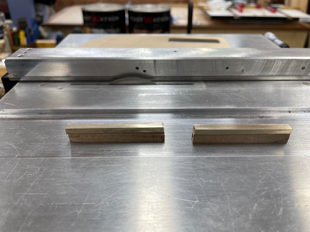
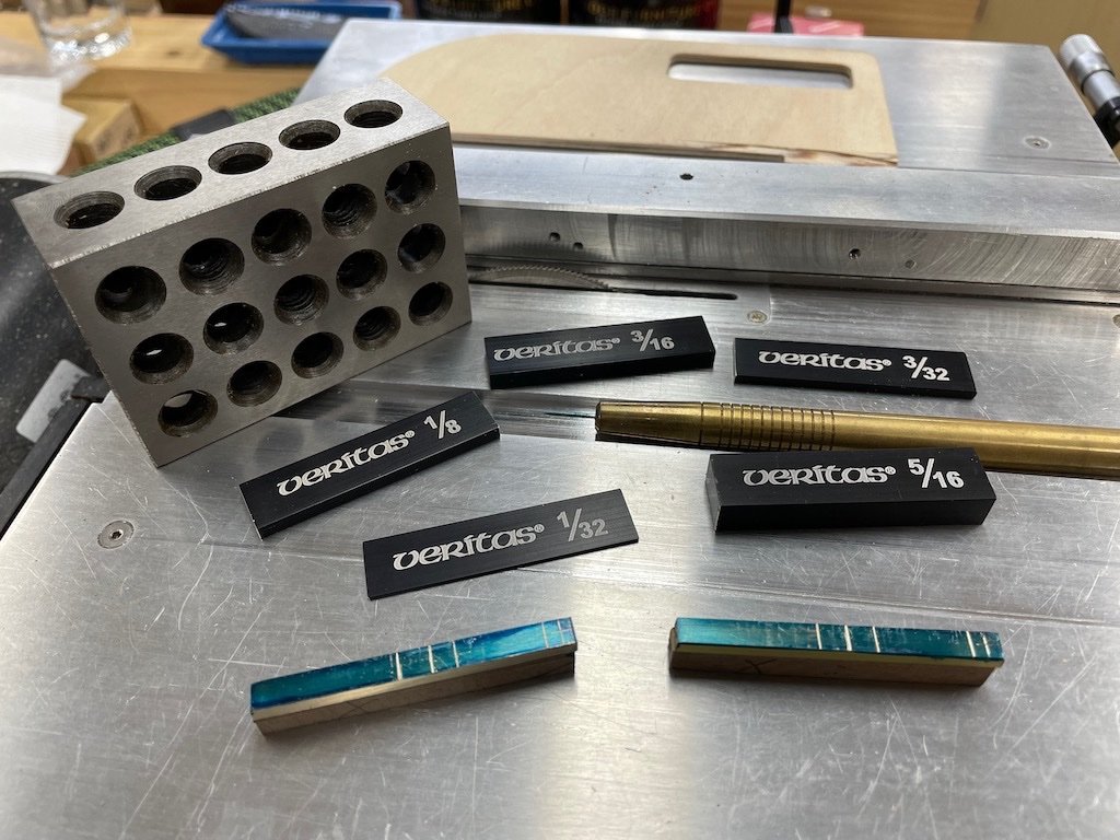
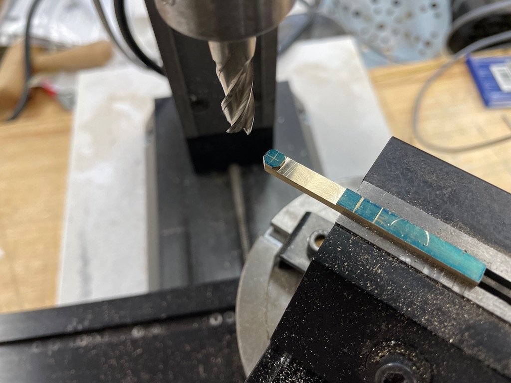
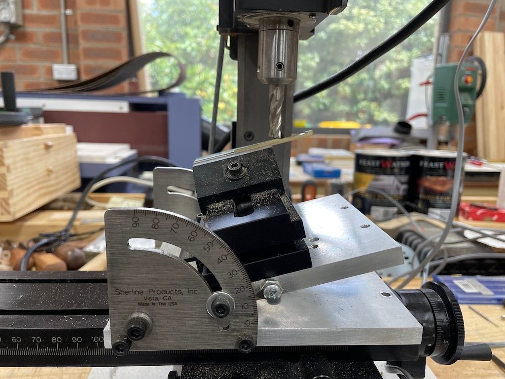
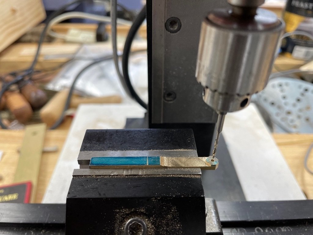
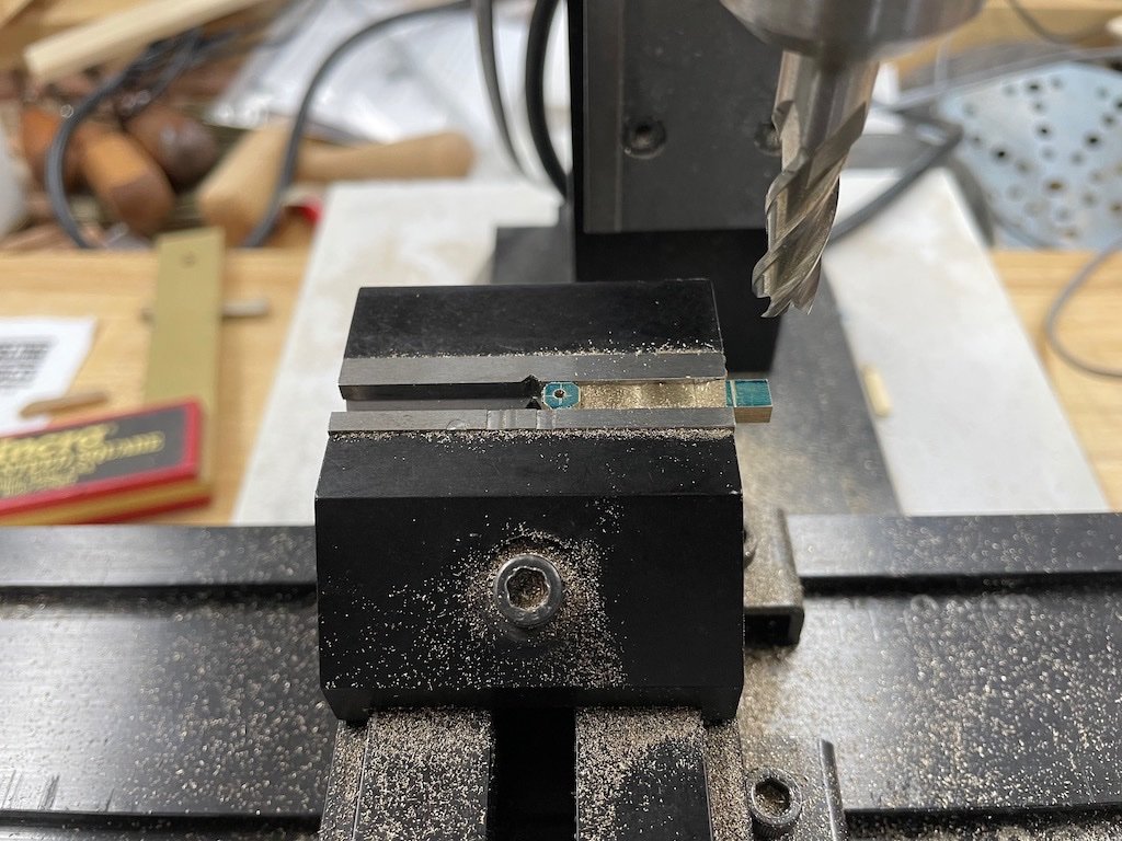
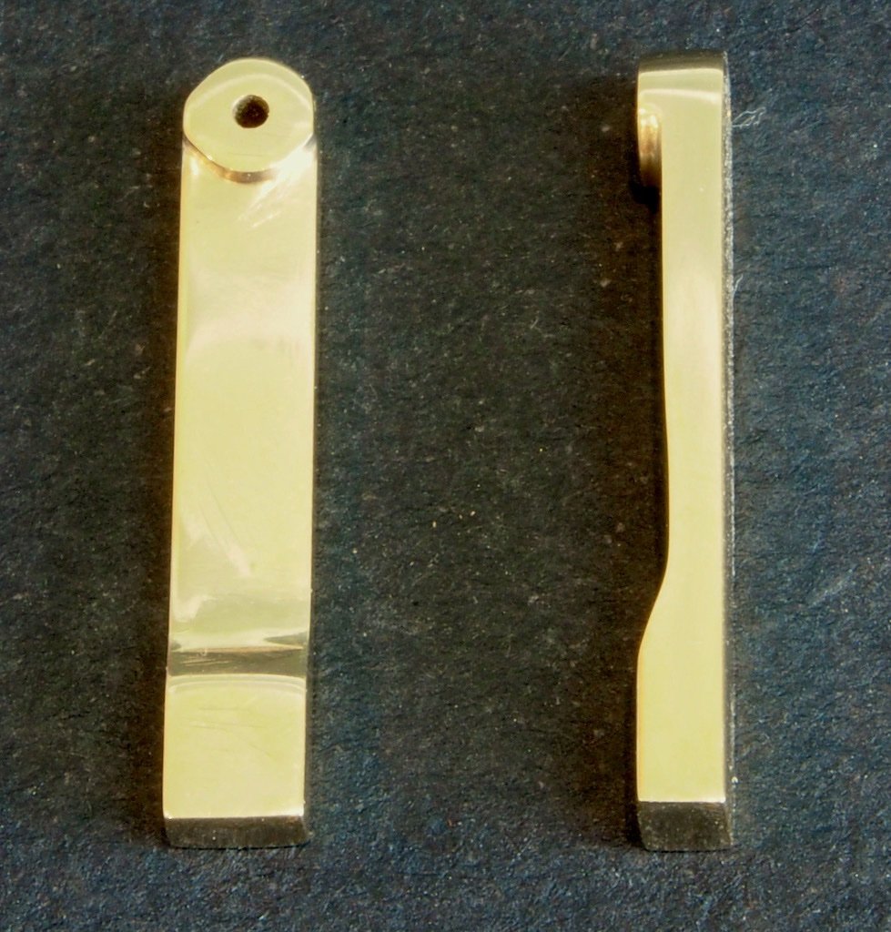
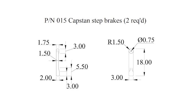
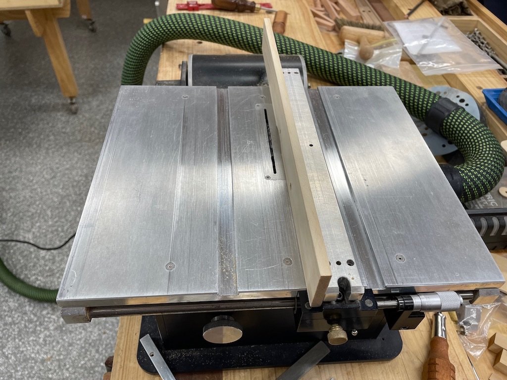
Capstan Step Brakes Although the Capstan Step Brakes form part of the Capstan Step sub-assembly, I’m treating them separately as we now venture into some metal work to fabricate these. These parts are an interesting example of where it is convenient to have scale conversions in both metric and imperial units. Here is the drawing from the plans, with full size measurements in decimal inches: All of these measurements convert conveniently to scale fractional inches, which is great for initial stock sizing and layout. However, when it comes time to work the pieces in the mill, I need metric measurements. First up, although Toni said she made hers from three separate pieces of brass silver soldered together, I decided to mill them from a single piece. The overall size of these parts dictate a stock size of 1/8” thick by 3/16” wide. I had some 1/8” brass flat-bar to hand, so the first job was to cut it down to size. To do this, I used double sided tape to fix the large piece to some sacrificial MDF and cross-cut it to a useable length using a slitting blade in the Byrnes saw with the sliding cross-cut table. I used multiple very light cuts until I was through the brass and into the MDF. I deliberately cut the piece twice as long as the finished size so that I would have plenty of “handle” when working the part. I then removed the cross-cut table and set the fence to the final width and used the same cutting technique to produce my starting stock. Here’s the original piece of flat-bar stuck to the MDF and ready for initial cutting: And here’s the outcome of the saw table processes: I then used some engineer’s marking fluid, a home made scribe, and some set-up blocks to layout the reference marks. This is where the imperial units were very handy. I set up the mill with a 5/16” end mill cutter and cut the main parts. I set the vise in the rotary table for this so that I could also roughly shape the end to an octagon prior to final finishing (an idea I picked up from Tom’s (UsedToSail) log). I then moved the milling vise to the tilting table and set the table at a 15-degree angle to mill the sloping section. The vise was then returned to the mill bed and the holes drilled in the end. The diagrams call for a 3/64” (scale) hole which equates to 1.2mm. However, I found that the 3/64” brass I had for the bolts would not go through this, so I opted to use a 1.3mm drill instead and this gives a nice sliding fit. The drilling was done using the Sensitive Drilling Attachment on the mill. Finally, the piece was reversed in the vise and the end mill cutter re-installed to cut the piece to final length. With all milling operations complete, the parts were then hand finished using files and sanding sticks. Here is the final result: Not perfect, but I’m happy with these. They will be chemically blackened in due course. On reflection, I could have done the milling sequences in more efficient order but then again, I had nothing better to do with my day…. Tomorrow’s challenge will be gratings…..
-
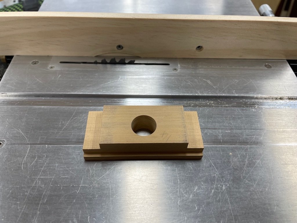
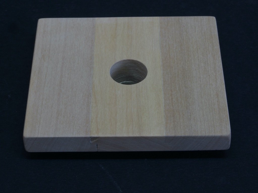
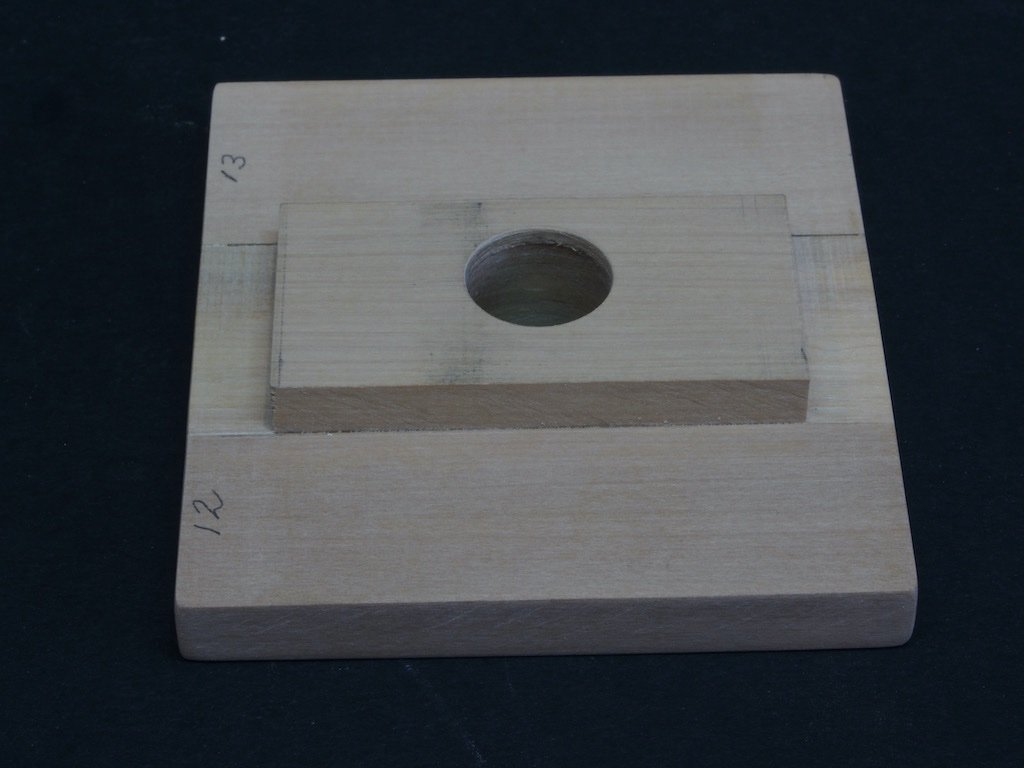
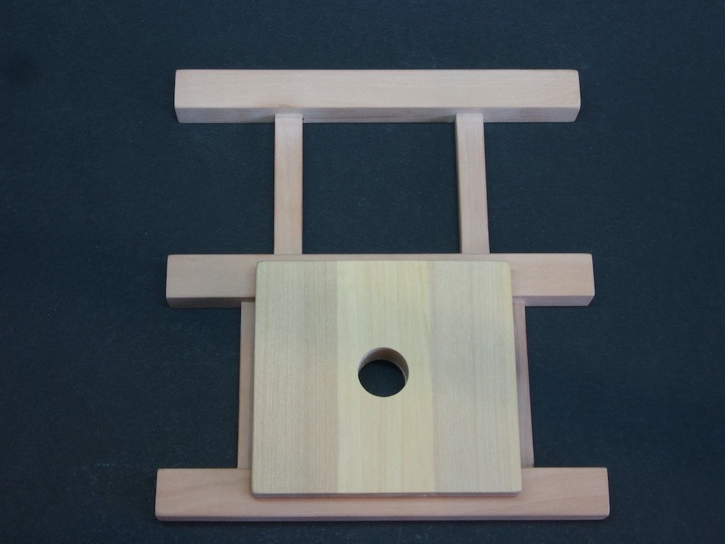
Capstan Step (P/N 104) The Capstan Step is comprised of three pieces, joined by half-lap joints along the length of each piece. It is complicated slightly be the centre piece being thicker than the two outer pieces as it extends below the surface of the deck, between. I was puzzled by some of the drawings and instructions, until I realised that Toni had made this centre (thicker) pieces from two thinner pieces. As I had already milled some timber to the correct thickness to use a single piece for this, I went ahead and used that. The half-lap joints were relatively easy to cut on the Byrnes saw. I attached a sacrificial fence that would allow me to partially bury the blade in the fence. Having set the blade height to exactly half the stock thickness (of the thinner pieces), I simply ran the pieces over the blade and edged the fence out slightly wider with each pass until the desired width was achieved. I used the micrometer stop to assist with the final passes to ensure that the exact width was obtained. One side of the centre piece needed the lap joint taking to a different height, but that was just a case of adjusting the blade height and leaving the remainder of the set-up in place. The underside of the centre piece also needed to be notched at either end to fit between the deck beams. I used the same process for this, using the same set-up with a different blade height and fence setting. Again the micrometer stop was used to sneak up on the final cuts to ensure a snug fit between the deck beams. Here is a shot of the fence arrangement: And here is the centre piece after all joinery operations are completed: In the above photo, I have also drilled the centre hole for the capstan spindle. I had to compromise here as the plans call for an 11/16” diameter hole and my drill sizes only included 5/8” or 3/4". I went with 5/8” and will adjust the size of the capstan spindle in due course. The individual parts were then glued up, given a light sanding and the sharp edges and corners given a gentle round over. Here is a shot of the underside, showing the additional work on the centre section: And finally, here’s a couple of shots with the Capstan Step temporarily located on the Deck Beams: I’m going to hold off on drilling the bolt holes for now. I think that all of the easy bits are now done. Next up is manufacturing the Step Brakes. I think I know how I’m going to approach that task…..
-
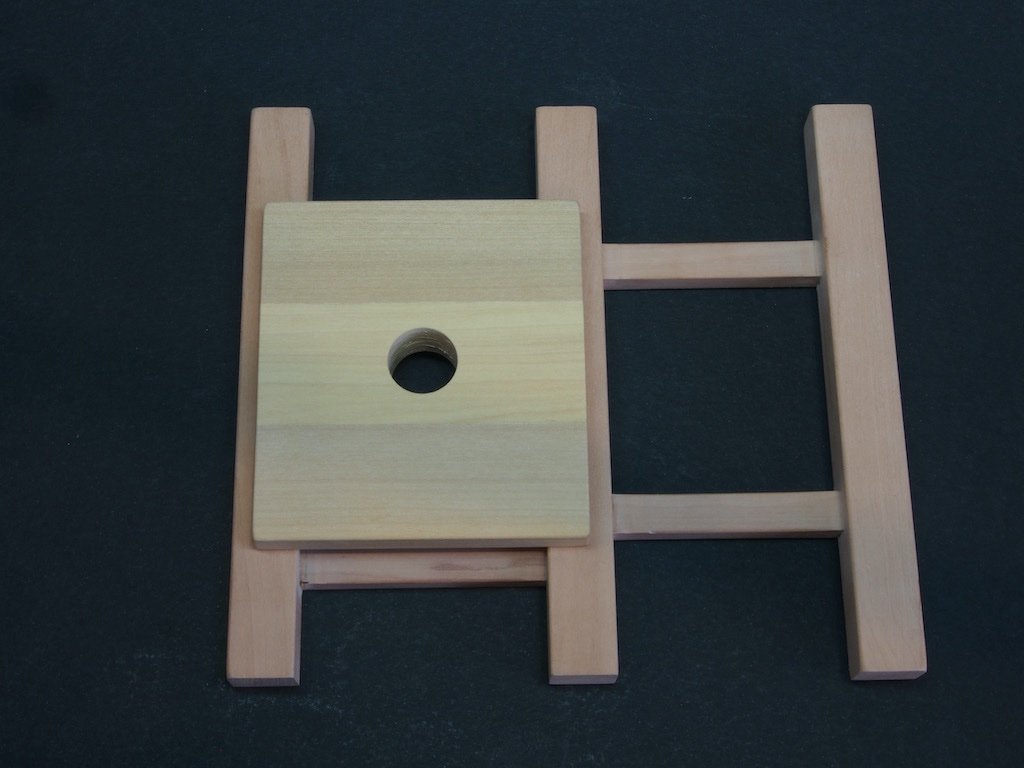
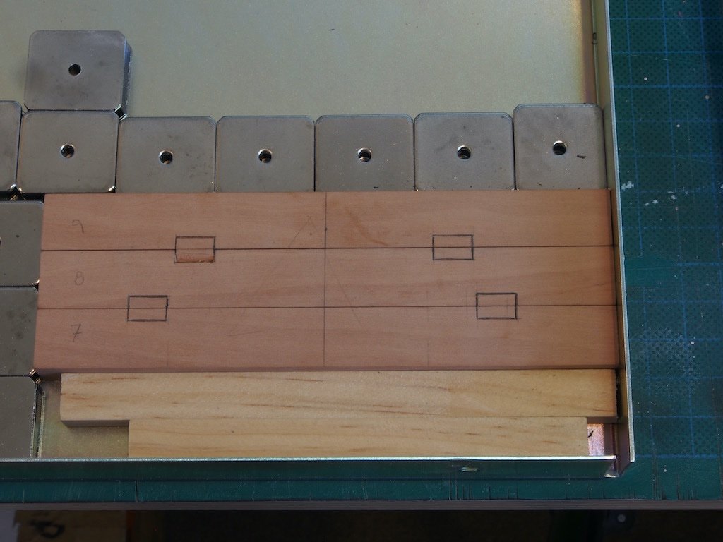
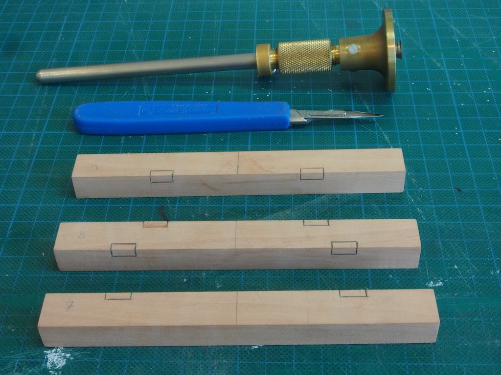
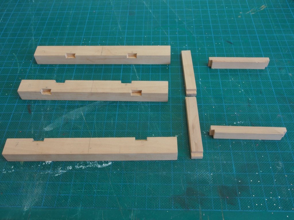
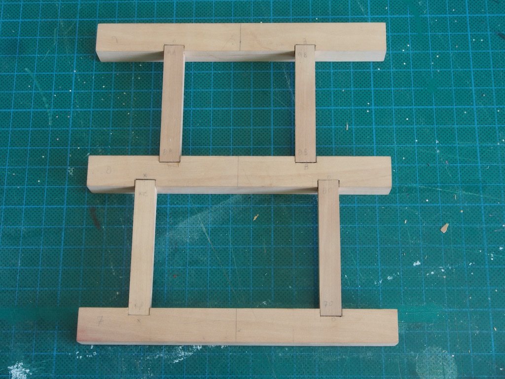
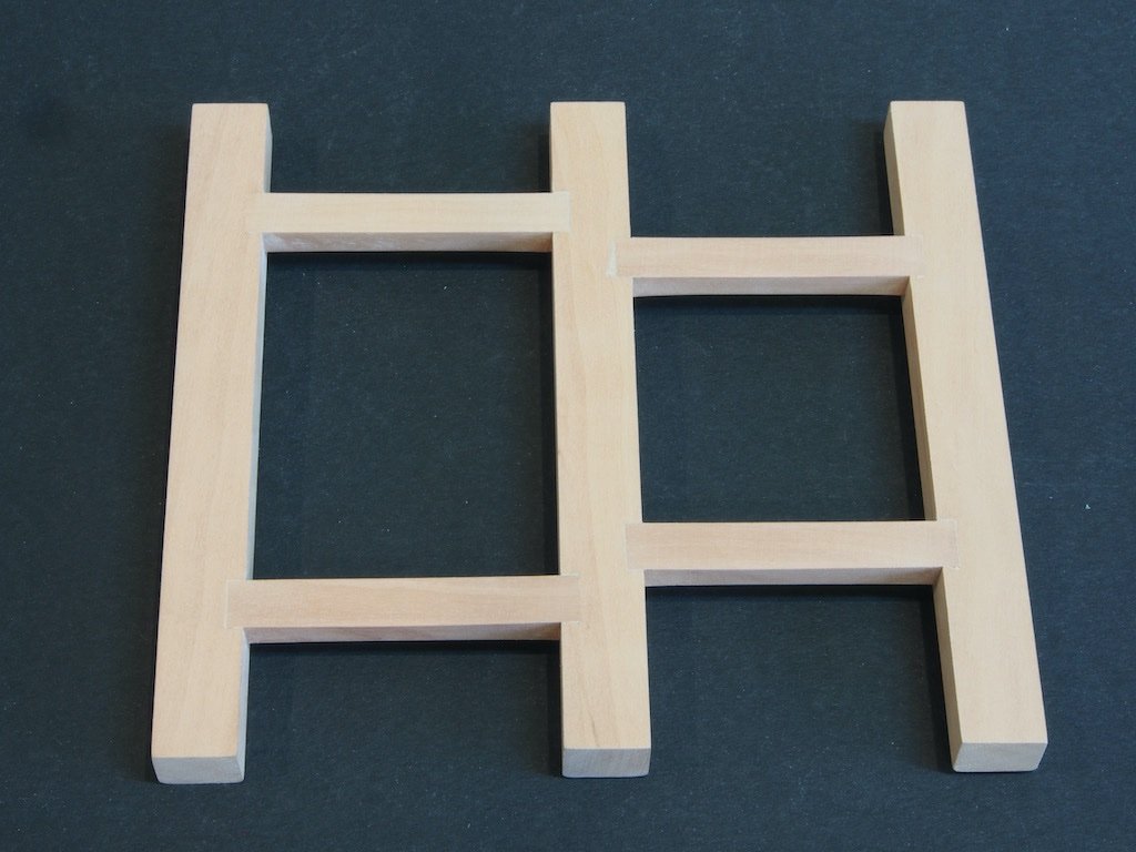
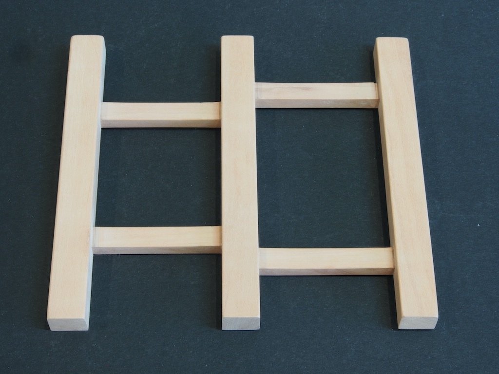
I am between modelling projects at the moment. Some time ago, I managed to acquire some additional stocks of very nice modelling timber from Jeff Hayes when he closed down his Hobbymill operation, so I decided that the Capstan model project from the NRG would be a good use for some of that stock and would give me a nice entry back into the scratch building side of things. Plans and instructions are by Toni Levine. As I have all of the toys, I decided to go straight for the Advanced version – hopefully, I won’t regret that decision down track! I will be building at a scale of 1:16, as Toni did in her version. I have downloaded all of the instructions and plans, ensuring that I had the amended version. The first challenge was to create a cutting list to determine the stock sizes I would need. As Toni has provided drawings with full size measurements in decimal inches, I decided that the easiest approach would be to create a spreadsheet to do all of the conversions for me. As my lathe and mill are both calibrated in metric units, I set up the spreadsheet to spit out measurements in both scale millimetres and scale inches (both decimal and fractional). I then went through all of Toni’s drawings and entered in the full size measurements and let the spreadsheet work it’s magic. While I was at it, I made a separate part of the spreadsheet a simple converter to use for other measurements as they crop up. This is proving to be a very useful tool, so I’ve attached it here in case anyone else might want to use it and save themselves from having to duplicate the effort. I take no responsibility for the accuracy of the information!!! Capstan Parts Scale Converter.xlsx With that task completed, I then went through my stash of timbers and selected some pieces that were close to the right thickness and processed them through my full size drum sander until I had all stock material to the appropriate thickness. I’ll be using Pear for the Beams and Carlings, Red Heart for the Hatch Coaming, and Box for the majority of the rest. I may use Red Heart for the Capstan Bars also, but I’ll reserve a final decision on that until I reach that point. Toni’s Practicum is very well laid out and not only identifies parts by part number but also groups these together into sub-assemblies. This is a really useful inclusion (thanks Toni 😊). Although the sub-assemblies can theoretically be completed in any order, I will follow along in the same order that Toni has used – I figure that way there is less chance for me to screw it up. The Deck and Hatch collectively make up Assembly 100. This comprises sub-assemblies 101 (Grating), 102 (Hatch), 103 (Deck) and 104 (Capstan Step). We begin with the Deck. Deck (P/N 103) Although I will need to use metric measurements when it comes time to use the lathe and/or mill, for the most part it is more convenient to work in fractional inches, simply because of the way the scaling works out (eg 1/2" vs 12.7mm). My spreadsheet gives me the scale size to the nearest 1/16 inch (although I can check against the decimal inches (thousandths) if required. A glance at the spreadsheet tells me that the Beams are made from 1/2" stock and the Carlings from 9/32” stock. These were cut to final length and width on the Byrnes Saw. The Beams were then numbered and marked with a carpenter’s triangle to ensure correct alignment before being arranged in my magnetic holding jig for marking out. I first marked the centreline and then laid out the mortices from the centreline. Markings were made lightly in pencil to begin with, with the inner edges of the mortices being defined from the measurements in the drawings, and the outer edge defined by placing the actual Carling on the beam to get the exact width. The marks were then transferred onto the vertical surfaces and a knife used to mark all cross-grain lines, while a marking gauge was used to mark all along-the-grain marks. This gave me some very well-defined layout lines. (I went over the cut lines in pencil just for greater visibility). The mortices sides were then cut using a razor saw (in much the same way as one would cut the sides of a half-blind dovetail) and the remaining waste removed slowly and carefully with a full sized very sharp 3/8” chisel. The tenons were cut on the Byrnes saw using the sliding cross-cut table and a stop to ensure that all tenons were exactly the same size. I had one very minor “oops” with the chisel – see if you can pick it. Here is the result: Once satisfied with the fit, the pieces were glued up. I was reasonably happy with results. I then made up a mixture of pear wood sawdust and diluted white glue and rubbed this over the joints and allowed it to dry overnight before giving it all a final sand with 240 grit today. As per Toni’s instructions, I also gave the underside edges of all Beams and Carlings a very slight round-over. Here is a shot of both the upper and under sides ready for the next step: The Capstan Step will be next...
- 43 replies
-
- 13
-
-
Looking great Dave. For my two cents (AUD), I think the blue is bit too much given the subtle tones you have used through timber species selection for the rest of the model. But, it’s your ship so you must go with what pleases your eye.