


gjdale
-
Posts
4,894 -
Joined
-
Last visited
Content Type
Profiles
Forums
Gallery
Events
Everything posted by gjdale
-
 Nice recovery Tom. As Toni said, we’ve all been there, done that - some of us more frequently than others!
 -
Great job Kevin - and amazingly fast too! Well done.
-
Fascinating project Ian - I’ll follow along for interest.
- 536 replies
-
- 3
-

-
- Quadrireme
- radio
- (and 1 more)
-
That is looking great (and huge!) Yves. You must be well pleased with this.
- 321 replies
-
- 6
-
-
- Finished
- Flower-class
- (and 1 more)
-
A good question Kevin, and Wefalck has provided a great answer. Thank you both for exploring this.
-
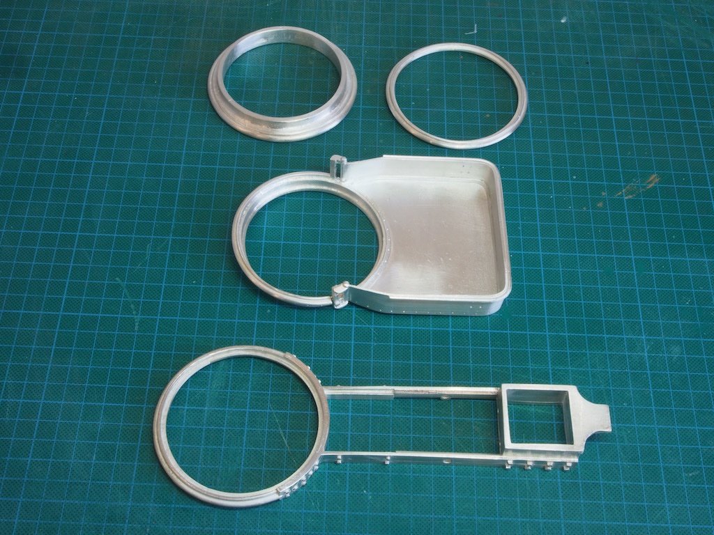
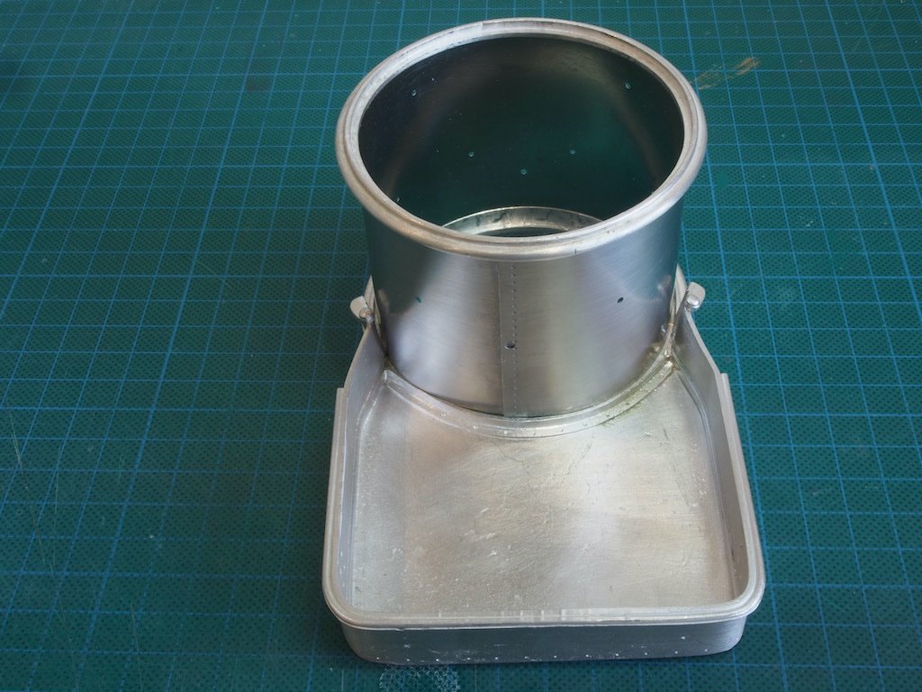
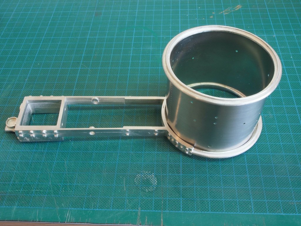
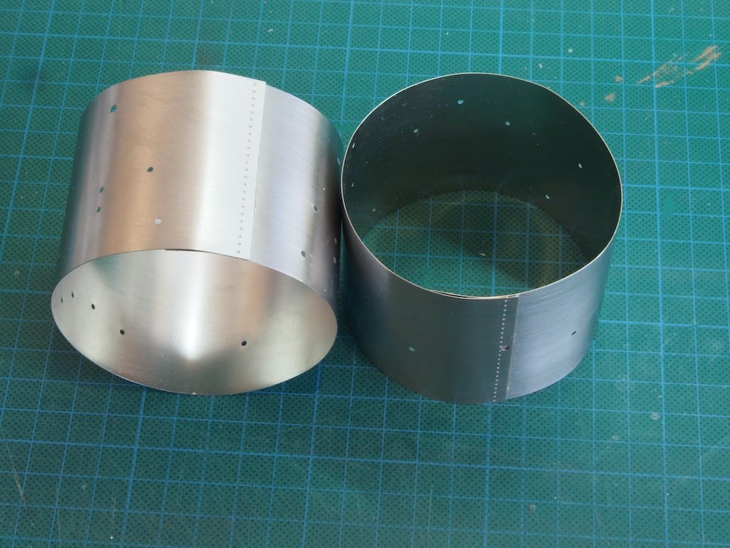
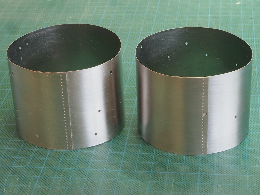
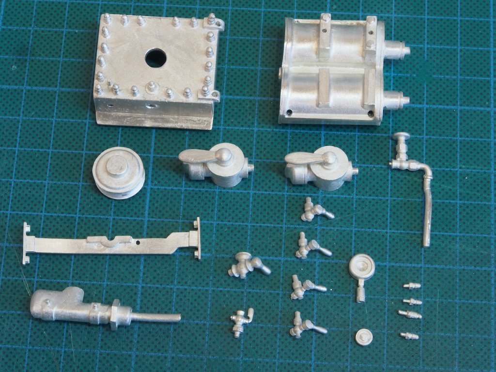
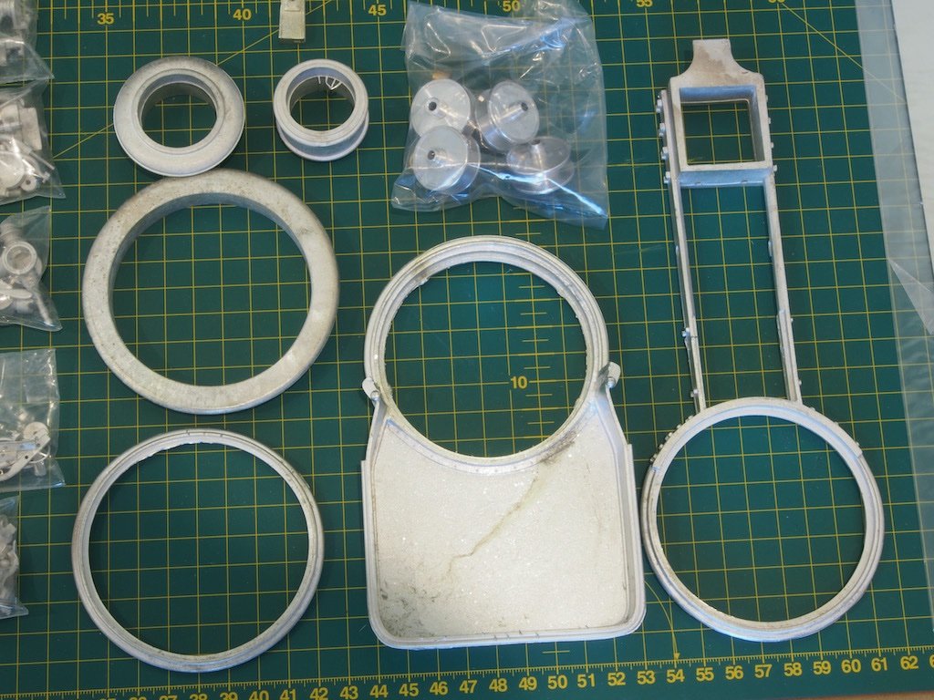
At last, I have managed to make a proper start on this project after a few distractions! Construction: Main Frame Construction begins by checking the alignment of the Main Frame Boiler Ring, the Boiler Ring, the Coal Bin and the Boiler Cap Ring. The Boiler Cap Ring (upper left in the photo) is used as the reference for all other rings. It is important for these to be as round as possible as the boiler walls index from these. The parts were then scraped, filed, and sanded of all extraneous casting imperfections (there were many!). The boiler walls are comprised of two sections, both formed from photo-etched stainless-steel sheets. The outer faced of these are first scrubbed in a horizontal direction with a Scotchbrite pad to simulate a brushed surface. The sheets were then slowly formed into cylinders by bending by hand and using the mainframe / coal bin along with the boiler ring to get them to the right size. Once they were the right size, I held them temporarily with masking tape and miniature clamps while medium viscosity, gap filling CA was applied on the inside surface of the joints. Once that had set, the clamps and tape were removed, and more CA was applied under the overlapped edges on the outside face. Masking tape was reapplied to hold everything in place while the glue set, and they were left overnight. The next day the tape was removed, and excess glue cleaned up with Acetone and cotton buds (Q-tips). All in all, this was a lengthy and difficult process – far more so than the description suggests! Lower boiler wall being formed using Coal Bin and Boiler Ring for index: Upper boiler wall being formed using Mainframe and Boiler Ring for index: And the finished boiler walls: These are now set aside until much later in the build. The reason for forming these now is so that subsequent paintwork on the other parts does not get scratched in the forming process. Attention is now returned to the mainframe and some initial components – the Lower Steam Box and the Upper half of the Water Box, along with various attachments. Locating and identifying some of these parts is a real challenge. Although the drawings are very good and the instruction manual has a lot of photos, some of the smaller parts take a while to positively ID. And although the instruction is very good, it is not perfect, and I’ve already found a couple of inconsistencies that it took a while to nut out. It is important to scrape, file and sand the casting imperfections and then dry fit everything prior to painting and assembly. All the locator holes had to be re-drilled to accommodate the indexing pins as well. Once all of these parts looked like they would fit in the appropriate place, they were scrubbed with a toothbrush in some warm soapy water before being set aside for painting. Here are the parts ready for the spray booth (along with the main frame – not pictured): It may not seem like much, but there is two full days work to get to this stage!

- 138 replies
-
- 13
-
-
Outstanding B.E. - but then again, we have come to expect nothing less from you! 👏👏👏
- 185 replies
-
- 2
-
-
- queen anne barge
- Syren Ship Model Company
- (and 1 more)
-
This is certainly coming together quickly Kevin - looking good.
-
He’s also a member of this forum Kevin - goes by the screen name “Xken”. He also designed the Allerton Steam Pumper kit I’m just starting. You’ll see some similarities in design principles between the two.
-
I see that this kit is another Ken Foran design, so I expect it will be a good one. Nice start.
-
I’ll be interested to follow along too. Looks like you’re all set for a great start.
-
Looks superb from this distance Mark!
-
Looking very sharp Mobbsie!
-
Fiberglass a boat Hull
gjdale replied to Riotvan88's topic in Building, Framing, Planking and plating a ships hull and deck
As long as they are sanded flush, they shouldn’t be a problem as you will be sealing them. If oxygen can’t get to them, they can’t rust. -
Kevin, I would think that the solution to that particular issue is to stop posting on the FB group, rather than stopping work on your model. Come back to it after AV and post your progress here. In all the time I’ve been a member here at MSW I don’t think I have ever seen that type of “trollish” behaviour - only ever encouragement, support and constructive suggestions.
- 322 replies
-
- 10
-

-
-
- enterprise
- caf
- (and 1 more)
-
I’ve only just stumbled across this outstanding build log Gary and all I can say is WOW!!! What a superb piece of modelling. Thank you for your detailed explanations of your processes too.
- 189 replies
-
- 10
-
-
-
Good question Popeye. The instructions call for both medium CA and 5 min Epoxy (as well as wood glue for the wood bits). I’m open to suggestions in this regard as I have very little experience with Britannia metal castings.
-
Good to hear that progress is being made Mobbsie, but……if there’s no pictures, it didn’t happen….😉😎
-
Thank you one and all for the very kind comments and likes on the completion of my Longboat model. Unfortunately, as I was setting up to take some "what's in the box?" photos for my new build, I knocked the camera and tripod over onto the Longboat. By a stroke of good luck, damage was minimal and relatively easily repaired - a little glue, a lick of touch up paint, and some re-tensioning of the rigging and all is good. No photos of before and after but rest assured all has been put to right. Just need to find a safer temporary place for the longboat until her permanent home is decided.
- 109 replies
-
- 3
-
-
- medway longboat
- Syren Ship Model Company
- (and 1 more)
-
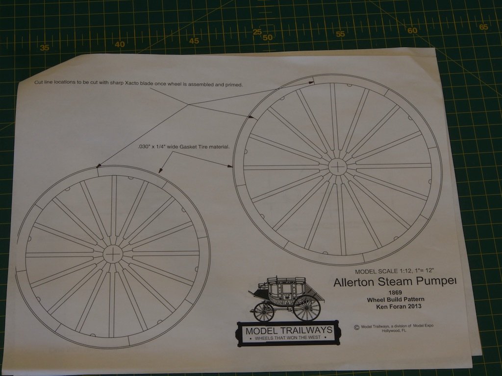
Thanks for all the interest folks. I hope to make a start in the next few days. There may be a slight delay while I make some minor repairs to my Medway Longboat. While I was setting up the photos for this log, I knocked over the camera and tripod - right onto the longboat! Fortunately, damage was minor and won’t take much to fix. Ken - there is no jig for the wheels, only template patterns. The wheels are an interesting part of the construction in their own right. It’ll be a while before I get to that stage though.
-
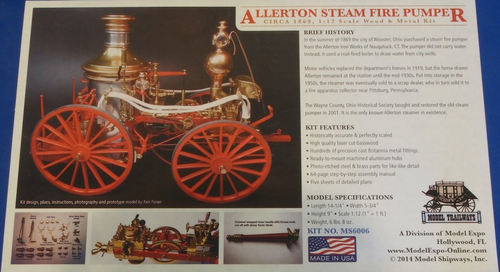
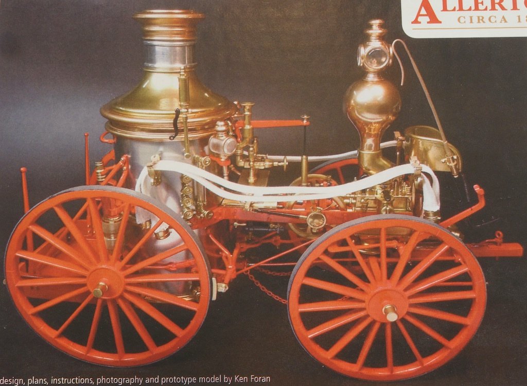
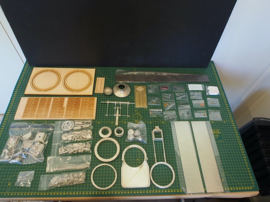
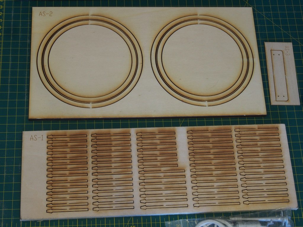
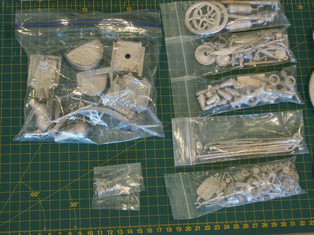
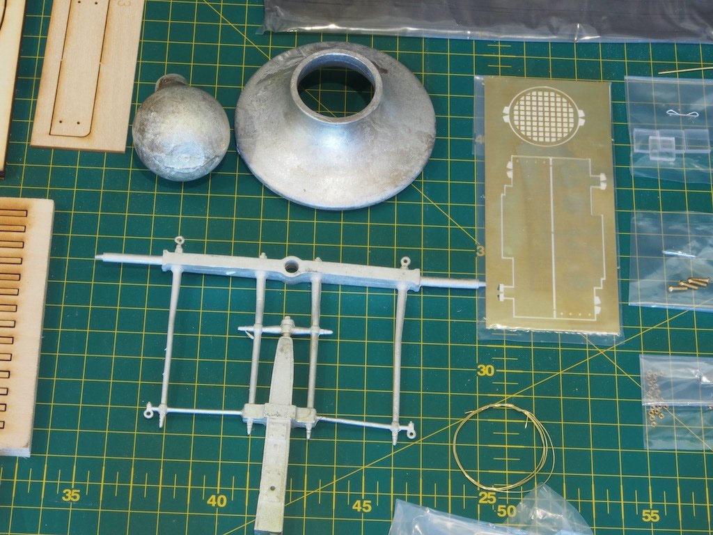
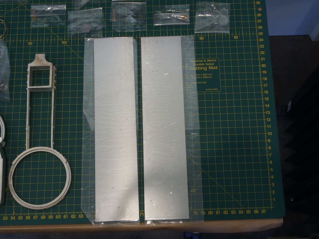
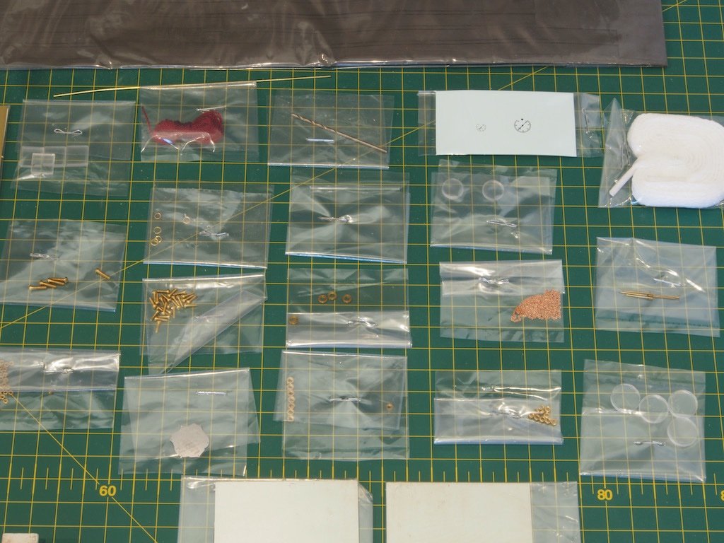
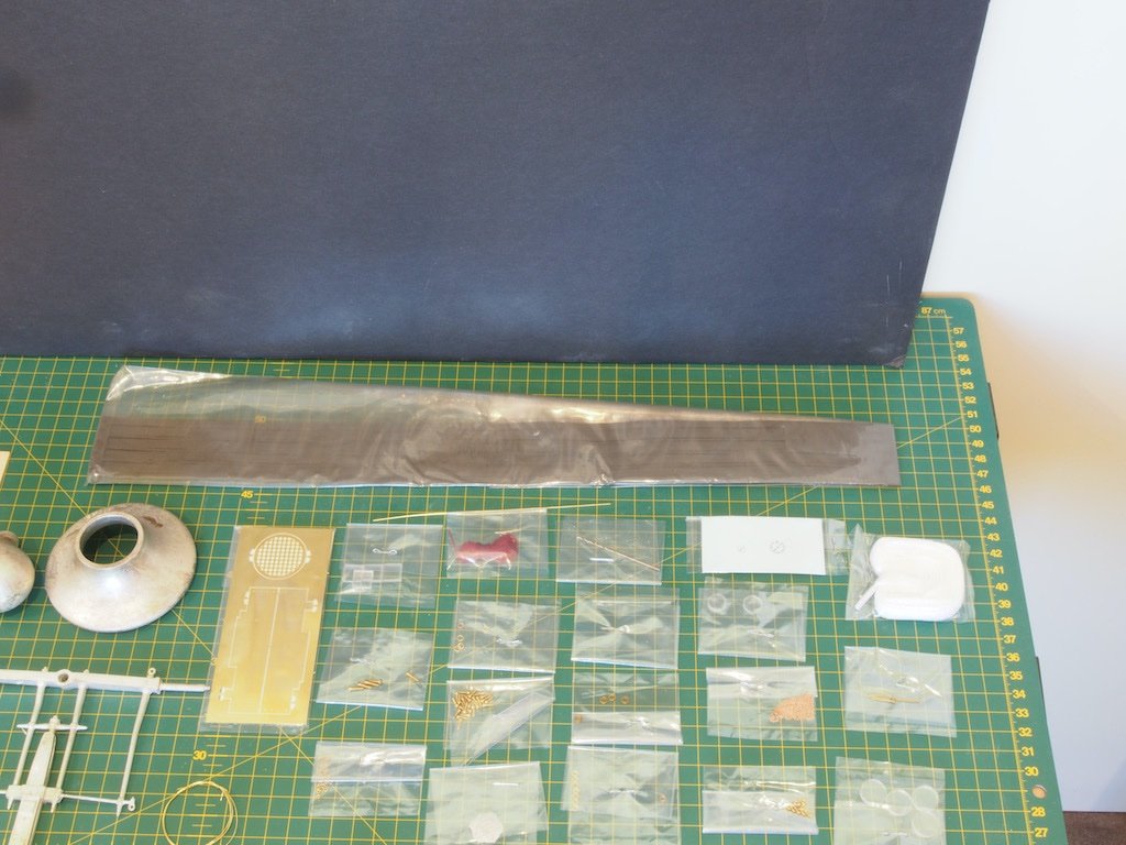
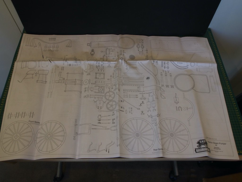
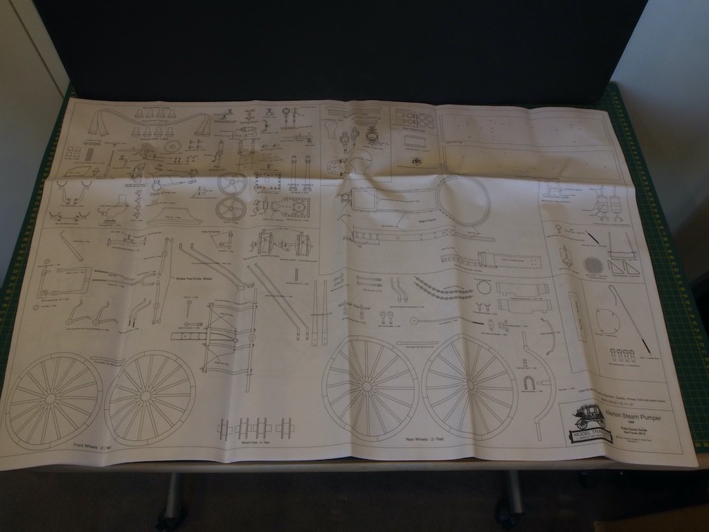
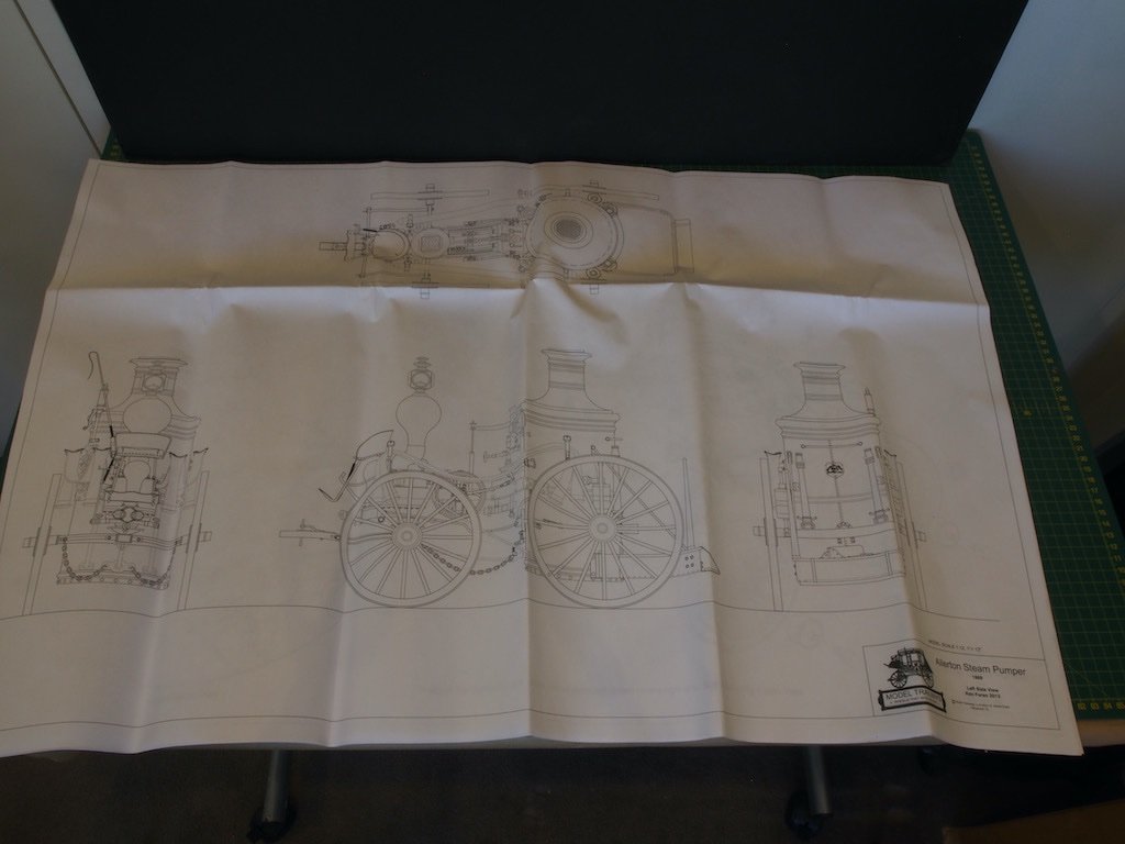
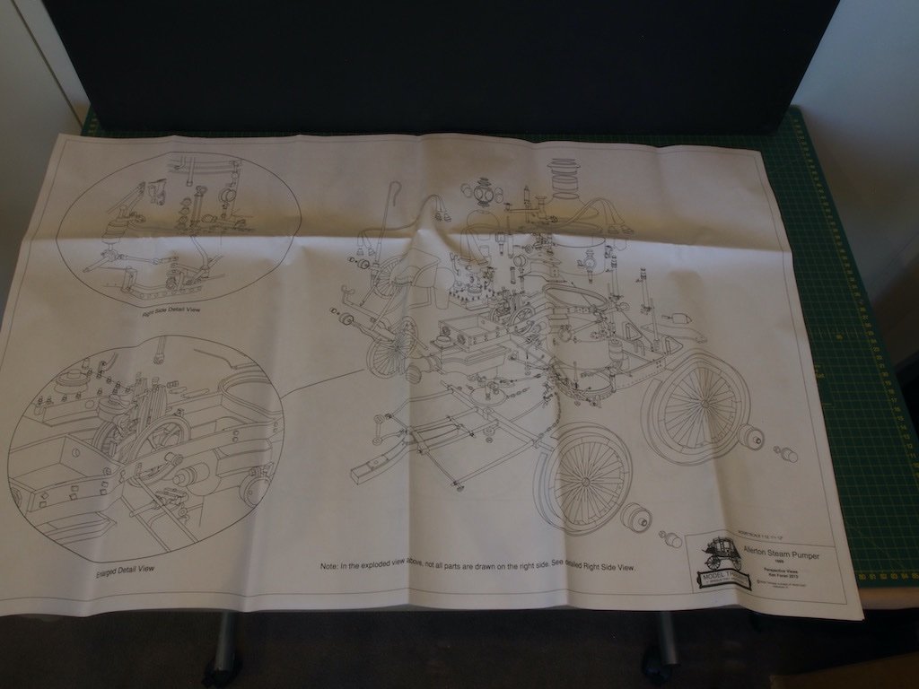
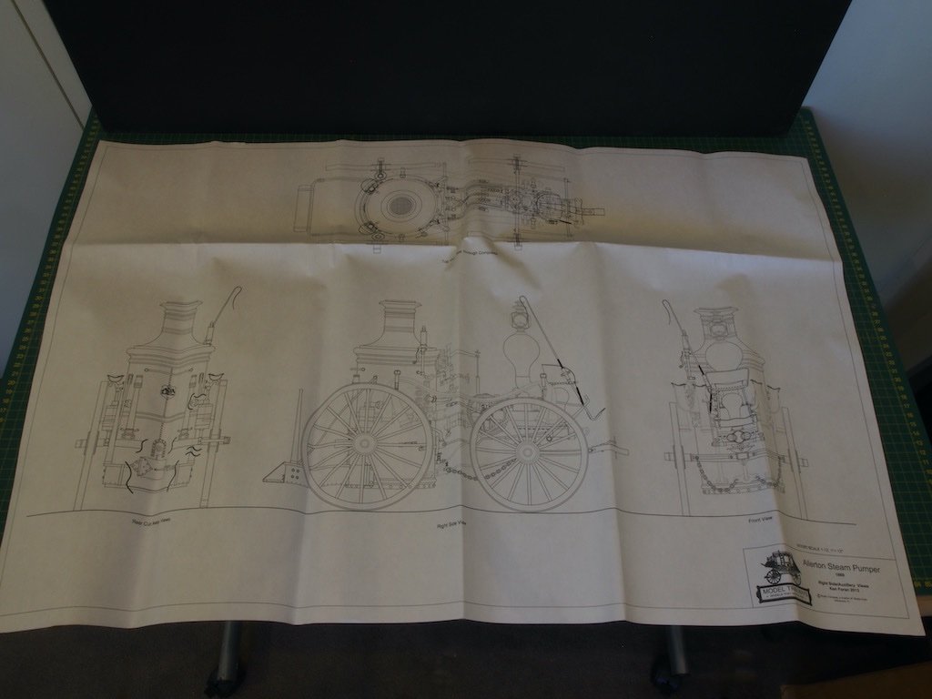
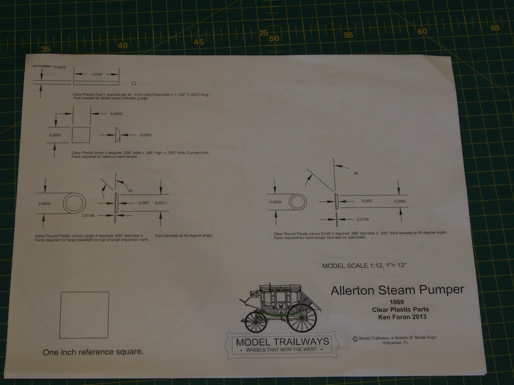
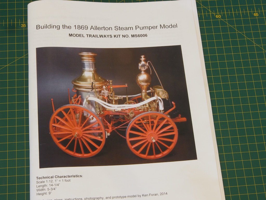
Introduction Anyone who has followed my builds will know that I have a fairly eclectic taste in models, and this is no exception. I bought this kit on a whim one day several years ago when Model Expo were having one of their frequent sales. I thought it would make a very attractive addition to my model collection, and my wife liked it too, so what was I to do? This model was designed by Ken Foran (a well-known member of MSW), who also did the plans, instructions and prototype model. In addition to being a member of the MSW forum, Ken has also published the book Model Building in Brass, which is a must have coffee table and go-to reference book. Ken’s work is truly outstanding, and I only hope that I can do his gorgeous design justice. Rather than re-type the history of the Allerton Steam Pumper, I have included a photo of the box lid, which tells the story. The model is in 1:12 scale (1” = 1 ft) and the completed model measures 14 ¼” (362mm) long x 5 ¾” (146mm) wide x 9” (228mm) tall. What’s in the box? The kit contents are interesting in that there is very little wood at all. What wood there is, is laser cut basswood and appears to be of decent quality. There is a plethora of cast Britannia metal fittings, some nicely machined aluminium hubs and a number of photo-etched steel and brass parts. With all of that metal in the build, the finished model weighs in at a hefty 6lbs 8oz (just shy of 3kg). The instruction manual is 64 pages long and includes quite a number of colour photos to support the detailed instructions. At first reading, this manual is a considerable step above the typical kit offerings. Also included is a set of 5 large pages of plans and drawings as well as two further pages giving details of clear plastic parts and wheel templates. Here is an overview of the box contents (minus plans): And here a few close ups of the various component groups. The only wooden parts – the wheels and their spokes: Several bags of Britannia metal parts: More cast metal parts and the machined aluminium hubs: More cast metal parts and some brass photo-etch: Some photoetched stainless steel parts: A range of small parts: More small parts and the wheel tyres in the long packet at the rear: The plans sheets: And the additional drawings: And finally, the instruction manual: I'll be back when construction begins in earnest.....
- 138 replies
-
- 20
-
-
Fiberglass a boat Hull
gjdale replied to Riotvan88's topic in Building, Framing, Planking and plating a ships hull and deck
Riotvan88, I was faced with a “never done this before” situation with my Chris Craft runabout. A detailed explanation of trials and then the actual process can be found in my build log here starting on page 5 at post 145 for the trials and page 6 post 153 for the actual process. I was guided a lot by a tutorial I found on the RC Groups forum.
