
.JPG.3b858ae7db6d3e5e48507bb4328943a5.JPG)
jlefever
-
Posts
156 -
Joined
-
Last visited
Content Type
Profiles
Forums
Gallery
Events
Posts posted by jlefever
-
-
I have a pair of the small pull type Japanese saws. They are a bit expensive but I really like them. They have very thin stainless blades, sharp teeth and no set to the teeth so they cut very smoothly. Since they're pulled through the kerf they tend to cut straighter and the lack of set allows cutting very near to if not against finish surfaces.
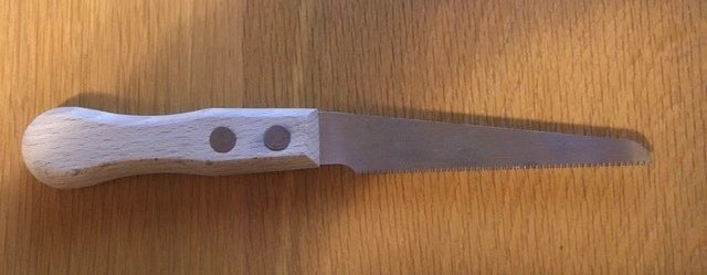
Highly recommended.
Jim
- thibaultron, Jaager, mtaylor and 1 other
-
 4
4
-
I'm sure you'll get other opinions on this question but my two cents worth.
Deadwood consisted of important structural members but at the time most wood ships were built engineering as we think of it didn't really exist. Instead skilled ship builders (we hope they were skilled) surveyed the material on hand selecting the right sizes, grain and supposed strength from which to cut the timber members. The wood had been harvested with care, selecting trees who's trunks and limbs were sound and strong from which members could be cut without flaws while respecting the natural wood grain.
Further important framing members would be fastened to the deadwood (cant frames) so the material needed to be sound.
So perhaps the answer to your question, the material was often selected from wood on hand but with with very specific attention to it's form, soundness and strength. it wasn't a casual process.
Jim
- thibaultron, mtaylor, druxey and 1 other
-
4
-
-
You can also try a composite soldered or glued up with short cut off metal tubes and brass washers. Washers should be easier to "turn down" with limited tools than a solid piece of brass.
Jim
- Moab, Roger Pellett, Keith Black and 1 other
-
4
-
1 Mini Projects
Mini Project 1 - The Dove’s Pump
When working on a project like the Dove I need to do a lot of thinking. Little of this process is rote to me and planning time is very important. One way to build planning time into such a project is to take a break and work on a different sort of project allowing thoughts of how the Dove will come out of its ridged box and how the planking will go marinate for a while.
The Doves need pumps. Here are the pump models I built.
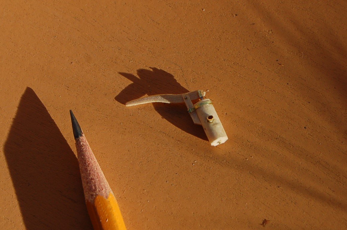
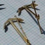
Figure 11‑1 - Pump for the Solid Hull Dove
Each Dove mounted a single pump of a simple wood tube type. Mine features a wood handle bracket attached to the pump barrel with a brass strap. The handle is fitted with a brass shackle used to lift the brass lifting rod that disappears down into the barrel. It’s also fitted with a brass spout with a lip to improve the water flow.
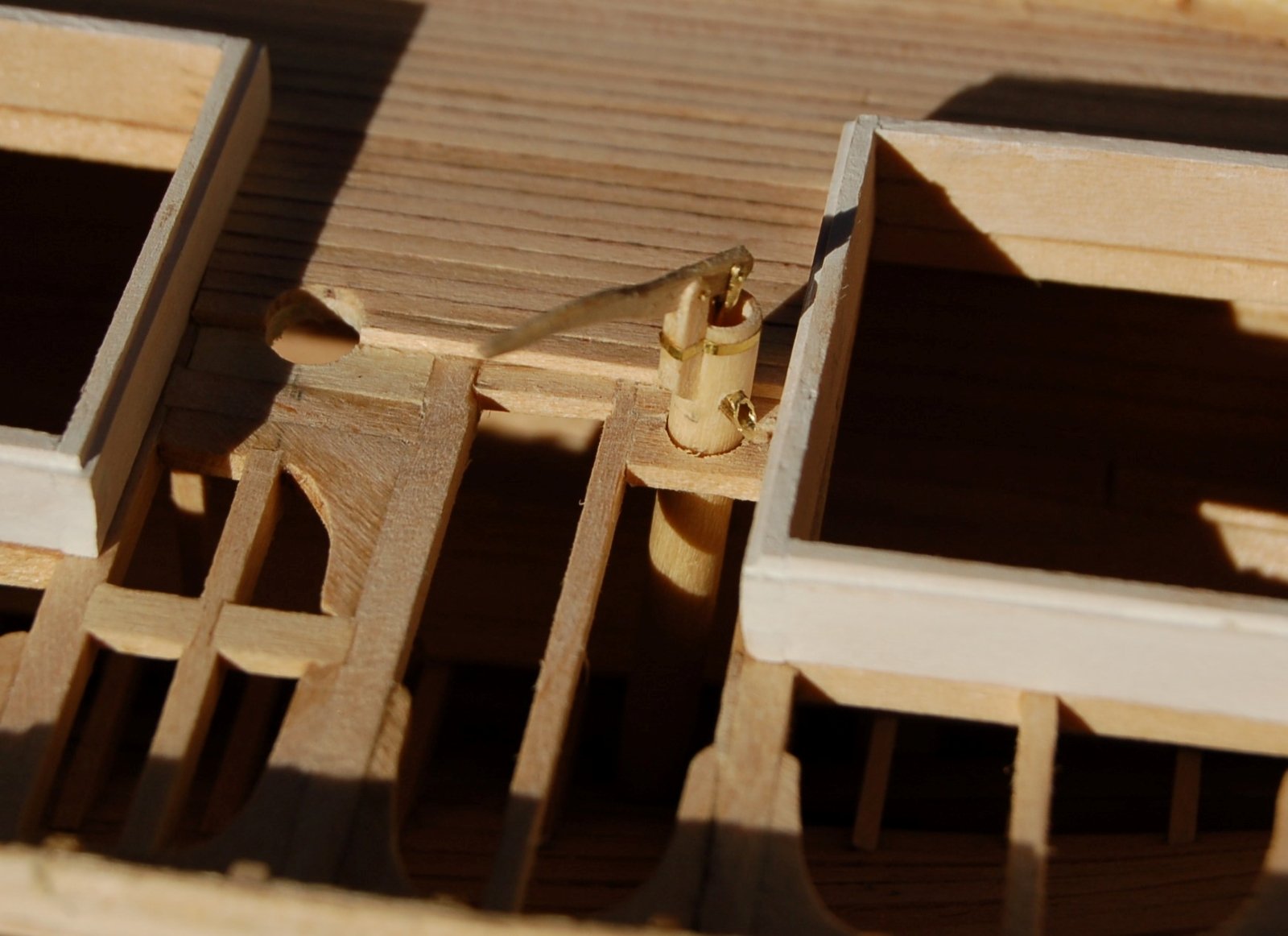
Here's the longer model pump for the framed Dove with its barrel projecting down through the deck, ceiling and into the open space between the ribs and beside the keelson.

Figure 11‑2 - Pump Projecting Down into the Hold
And mounted on the solid hull model…
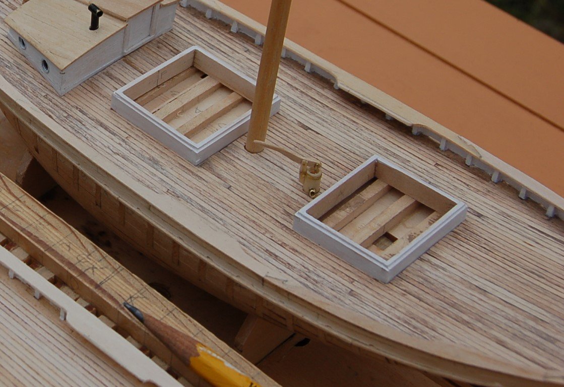
Figure 11‑3 - Pump on the solid hull Dove
- GrandpaPhil, Matt D, mtaylor and 1 other
-
4
-
To your first question, hatches and other deck openings are, like windows and doors in buildings, a point of weakness. It is typical to add extra structure around such openings to replace the strength lost when holes in the decking are needed, especially large holes.
Not a bad question at all and knowing why elements are there improves the likelihood that they will be modeled accurately.
-
Work on the Main Deck (2)
In my last post I covered work done topside before the start of the deck framing. Once finished the next task was the actual decking. The final steps included completing the deck framing permanently attaching the forward deck section and the cabin trunk and starting decking. I started with roofing the cabin trunk. In the next image, the deck is ready for decking and the cabin roof is half complete.
This is as complete as the roof will get. The companion has been framed and the stove pipe strapped to a cabin beam. More important, the waterway has been started. You may note from the pieces laying about, broken and whole that I found it a struggle working out the scarf joints while coping the planks around the many stanchions.
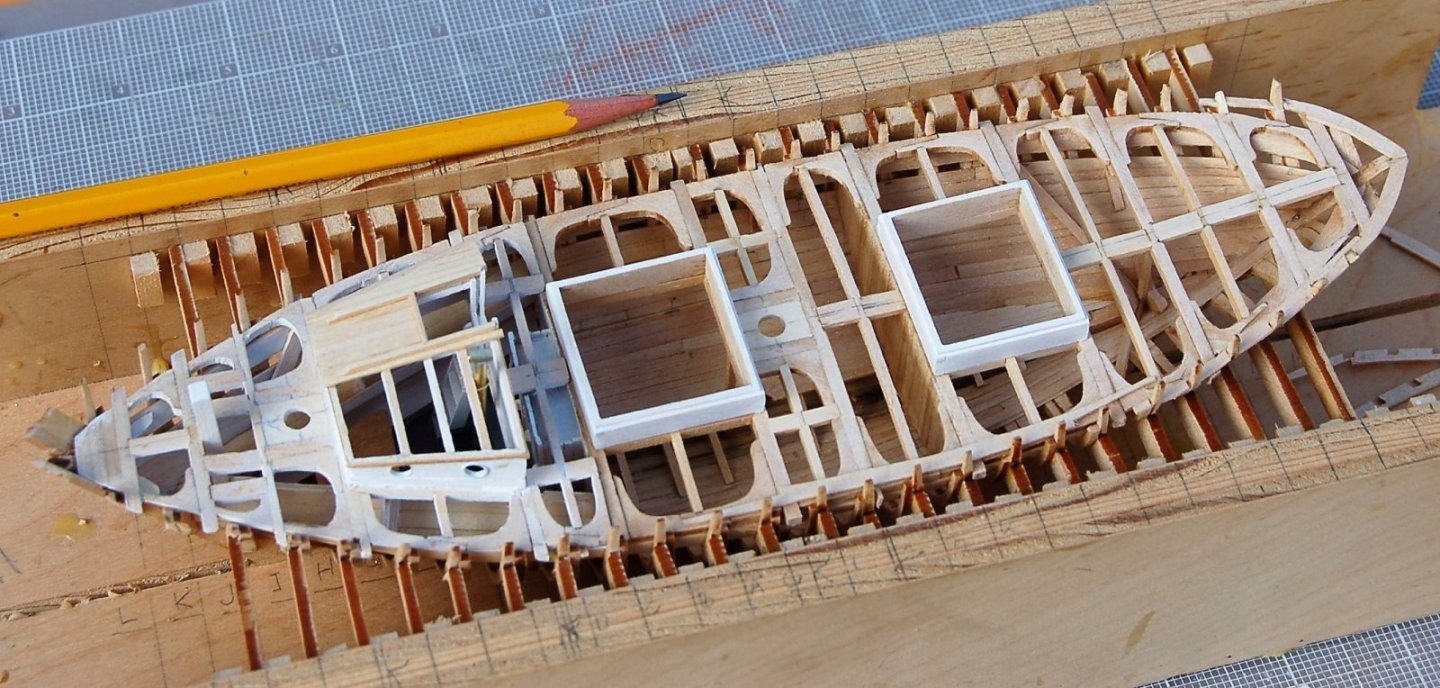
Figure 10‑9 - Cabin Trunk and Main Deck framing in Place
In the next image the perimeter plank or waterway has been installed all around the deck and decking is in place. Again, only half the deck will be covered with this, the framed Dove, which will be presented as if still under construction. The decking was worked from the centerline toward the railing with nibbing worked in where appropriate. Calking has been simulated by staining one face of each joint with permeant brown Sharpie marker. The design decking was to be 3” by 1 ¾” and I’ve used 1/16” strips to create scale planks.
The single plank running through the hatch will be cut away when I mount the hatch.
For now, it has been run from stem to stern to make sure the plank spacing would align on both sides of the hatches. The perimeter plank will be completed with a trim strip run outside the stanchions as a trim piece expressing the plankshear and joining the hull and rail planking. Part of this strip is shown already in place on the starboard side of the deck.
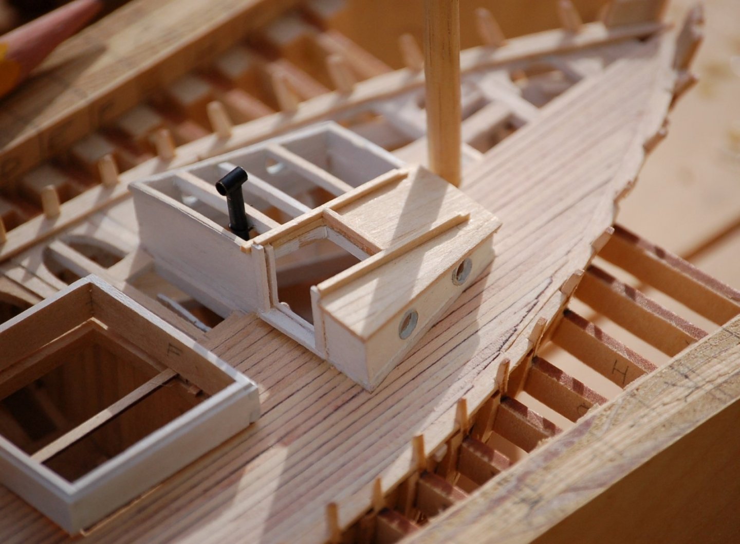
Figure 10‑10- Cabin Trunk and Main Deck in Place
Decking
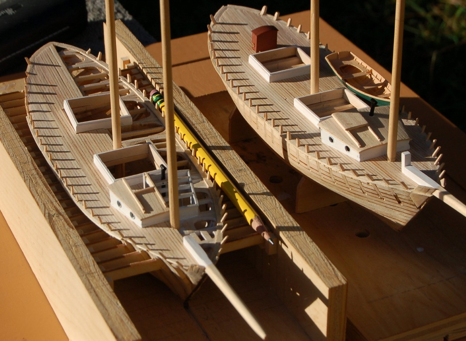
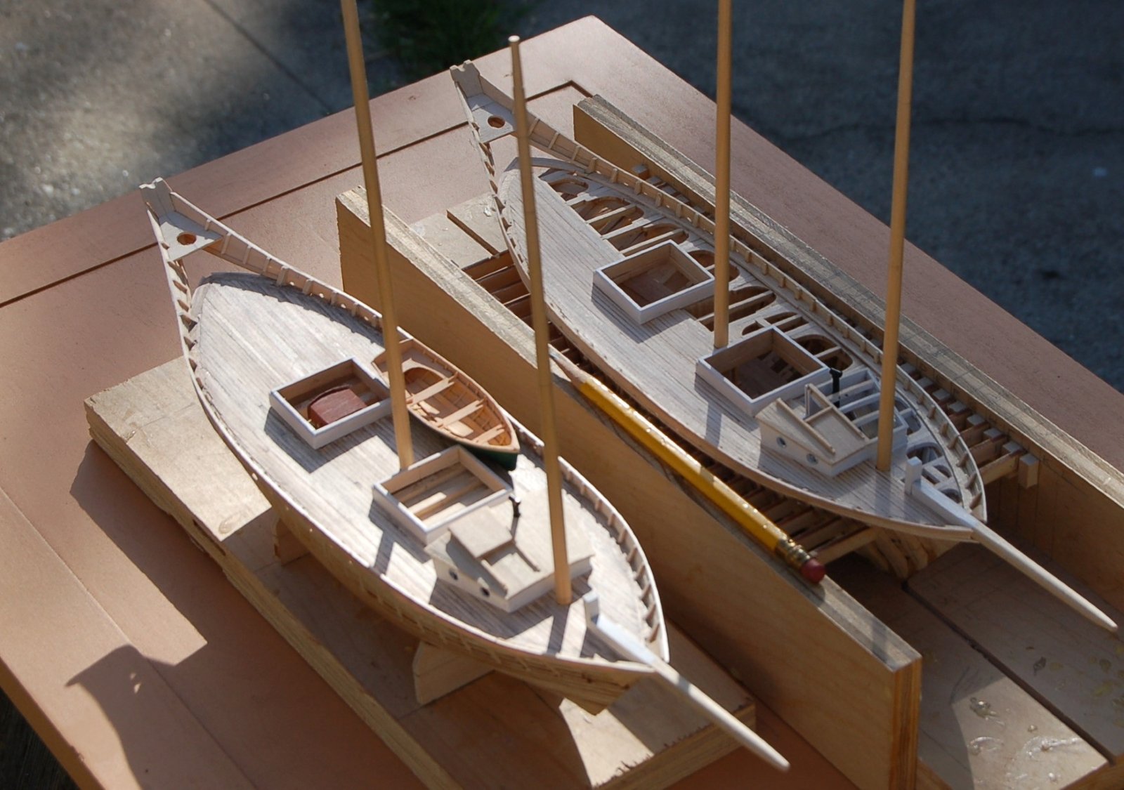
Here are both Doves with the deck complete and the cabin trunks in place with complete companion ways and roofs.
The Solid hull version is sporting a boat and binnacle. I’ll discuss building these elements in a section on furnishings.
At this point two of the stanchions on the aft end of the framed Dove have been partially broken off They will need to be repaired before the next step which is installing the railings. The stanchions on the solid hull appear to have better stood the test of time. The photo must have been taken near the end of the day as the stanchion shadows are quite long for posts only a quarter inch tall.

Figure 10‑11 - Decking, a Big Step Toward Looking Like a Ship
Railing
The next project was planking the railing. It was another dramatic step especially at the stern where the railing breaks away from the hull and sweeps up to the terminating “Tombstone” it really identifies the Dove as a classic pinky. As previously indicated the railing is only a scale foot high, certainly not enough to keep off much water in any significant sea. Scuppers have been worked into the bottom planks with a fine “rat tail” file.
While the tombstone forms a convenient crotch for the main boom, the open railing, dramatically flaring back and upward toward the tombstone must have done little to keep the deck dry.
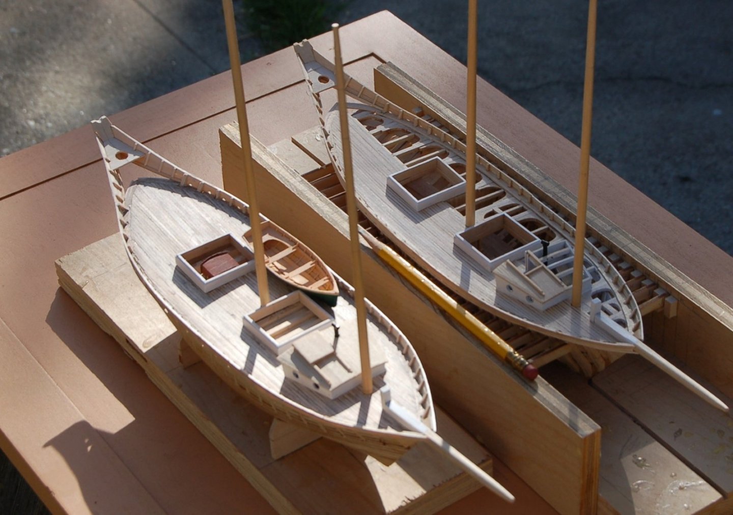
Figure 10‑12 - Railings
Top Rails
Before applying the top rail, I painted the stanchions and inside rail planking white and on the solid hull Dove also applied a lick of weathering to hint at a vessel that has seen some use. At three points along the top rail, the cap flares out to form a pin rail. The plans indicate that the top rails will receive a natural finish. I’ll paint them to suggest a natural mahogany.
The pumps seen in this image will also be described shortly as will the rudder and tiller that will rise through the opening at the rear of the vessel.
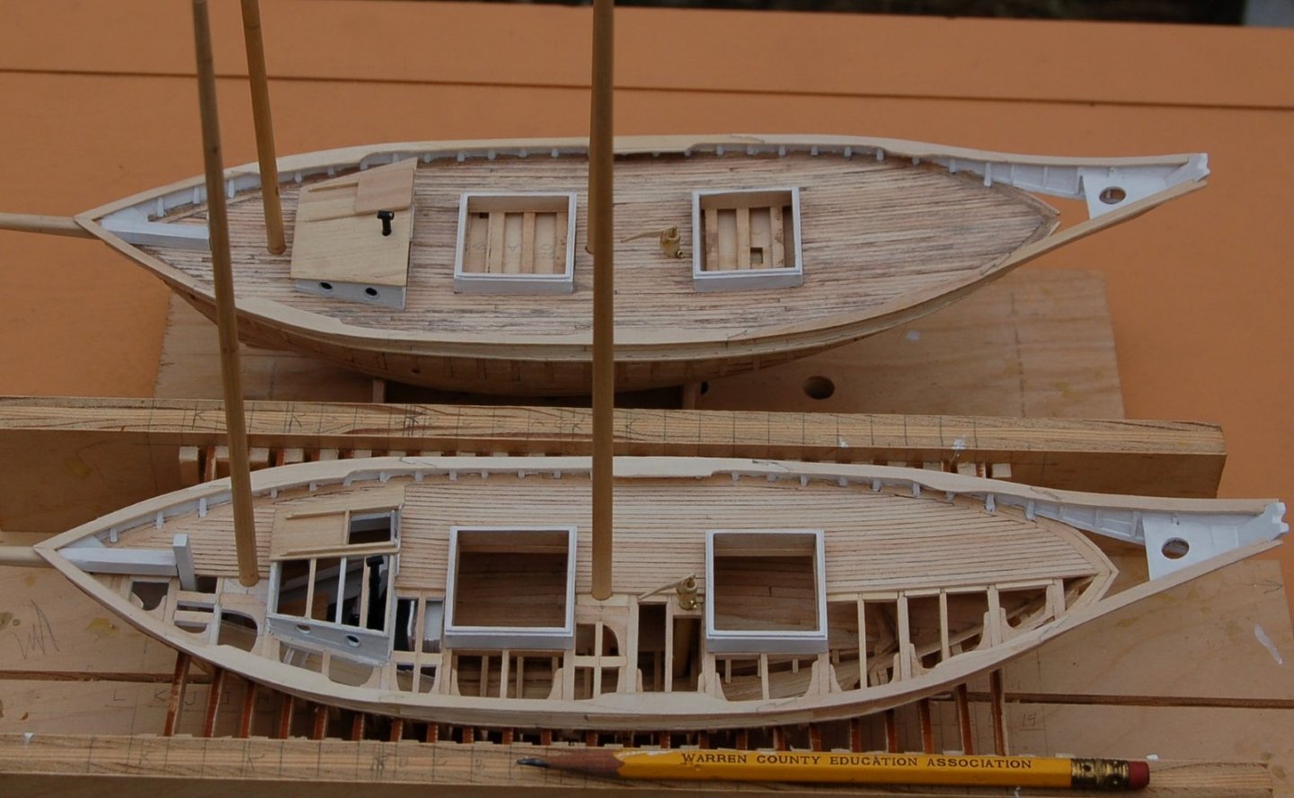
Figure 10‑13 - Top Rails
Top Rail Joints
The top rail was cut from four segments of straight stock and cut to profile without horizontal bending. All the top rail Joints several of which can be seen in this image used an interlocked scarf joint.
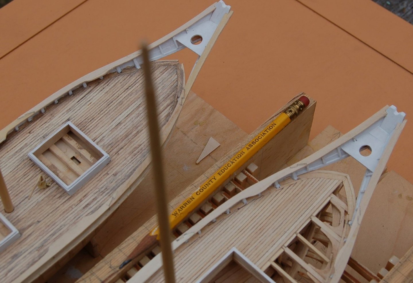
Figure 10‑14 - Rail Joints
This view focuses on the stern construction showing the decking, the perimeter plank and the construction of the railing.
The final view, on the next page is an overview of progress on the framed model. I’ve now reached the point where additional progress will not be possible without removing my little vessel from its confining box.
Nearly ready to come out of the box.
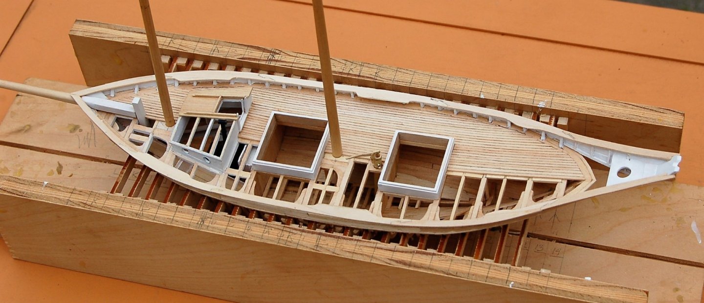
Figure 10‑15 - Approaching the moment the Dove will be removed from the Erection Box
However, before I take a deep breath and start cutting, I’ll bring you up to speed on a variety of Dove related projects.
That's it for now. I'm back to combing through my old photos. See you next time.
-
Work on the Main Deck (1)
Bow Sprits
With the below deck basically done and the cabin fitted out, it was time to move upward. The main deck framing is near complete but before moving on to planking the main deck I wanted to work out the hatches and cabin trunk as well as the bow sprit.
Here a bow sprit has been added to each Dove. They’re a foot square at the kingpost and round off quickly once past the hawse planks and outboard. The inboard end had been worked into a tenon which fits into a mortise in the kingpost. They’re small but look sturdy. At this point, they have been blocked out and fitted to the hull but are not yet fully shaped.
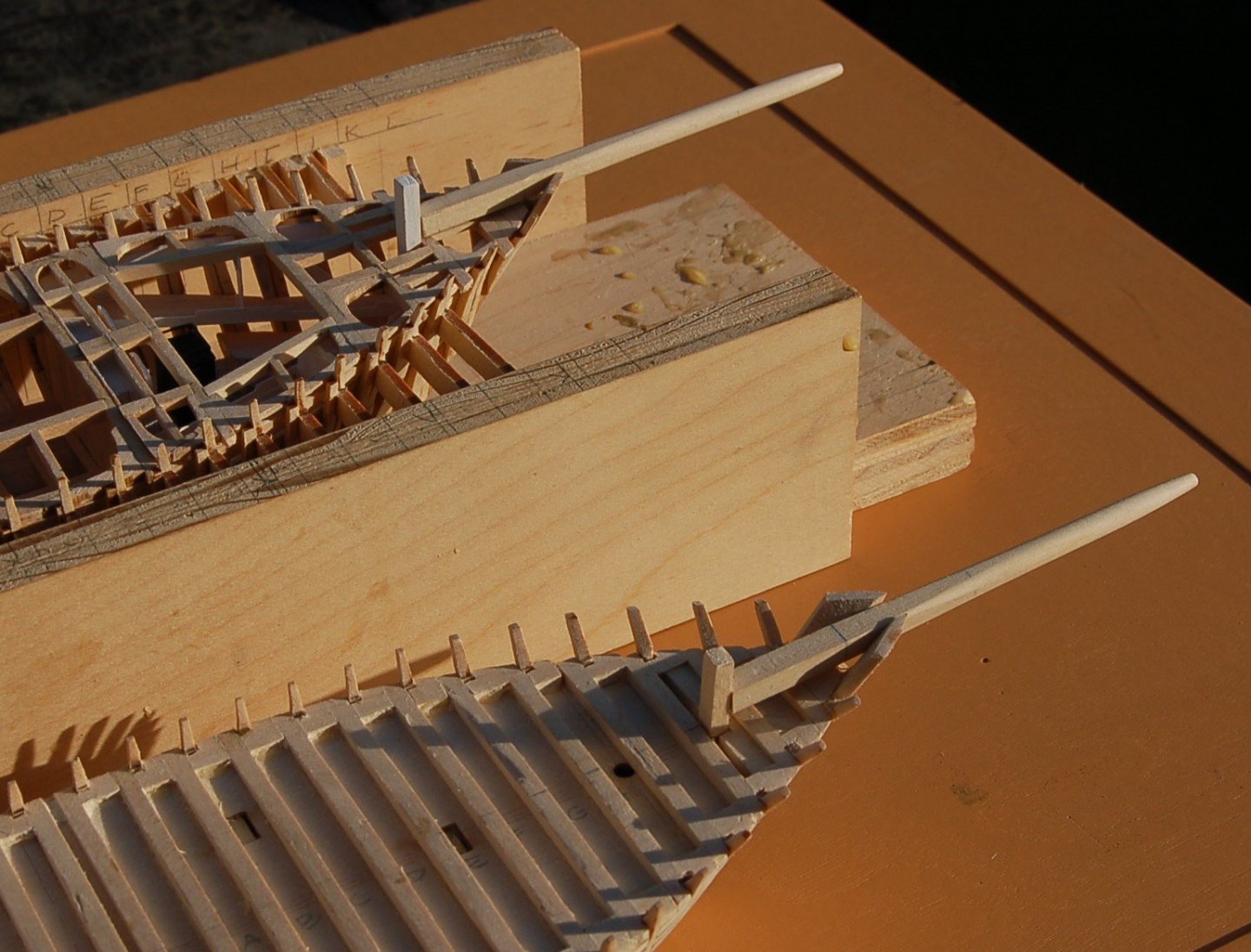
Figure 10‑1 - A Pair of Bow Sprits
If you look ahead a bit, or back to the first chapter images you will notice that before I finish up the contours of the Sprit tip have been redone, in part to accept a wye for the rigging. I used the same pole but reworked it a bit as I realized the need further tweaking.
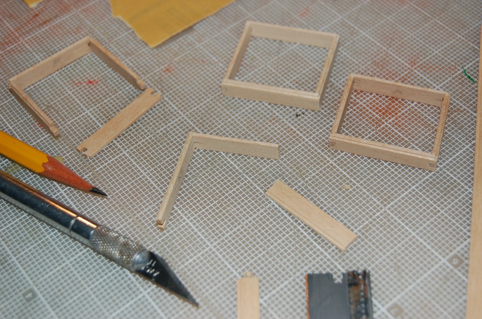
Hatches
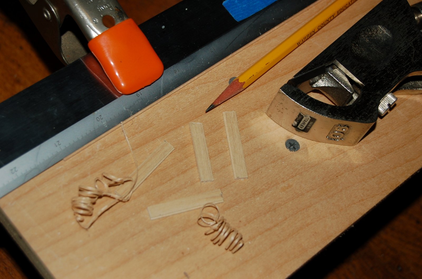
The Dove’s hatches started with strip stock but needed a reveal or rabbet along the top edge. To achieve the rabbet, I clamped my strip under a metal rule and used a small shoulder plane to peel off the edge of several pieces.

Figure 10‑2 - Planeing the Hatch Edges
Needing two hatches for each dove I cut eight lengths of this roughed out material.
Next the hatch segments were measured and mortises and tenons worked into the ends to approximate the more typical dove tails. The pieces were fitted and glued together and the small projecting ends trimmed and sanded. Just a bit of sharp edge work was needed to trim the rabbet ends and get an even edge all the way around.
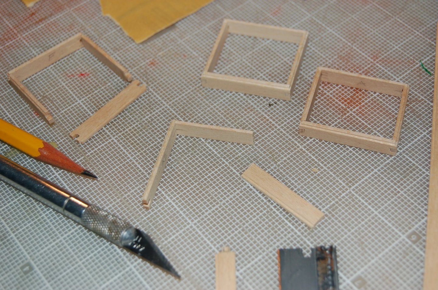
Figure 10‑3 - Gluing Up the Hatches
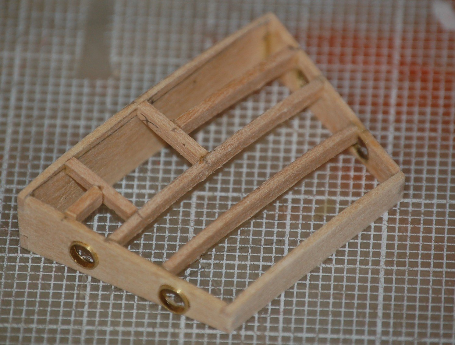
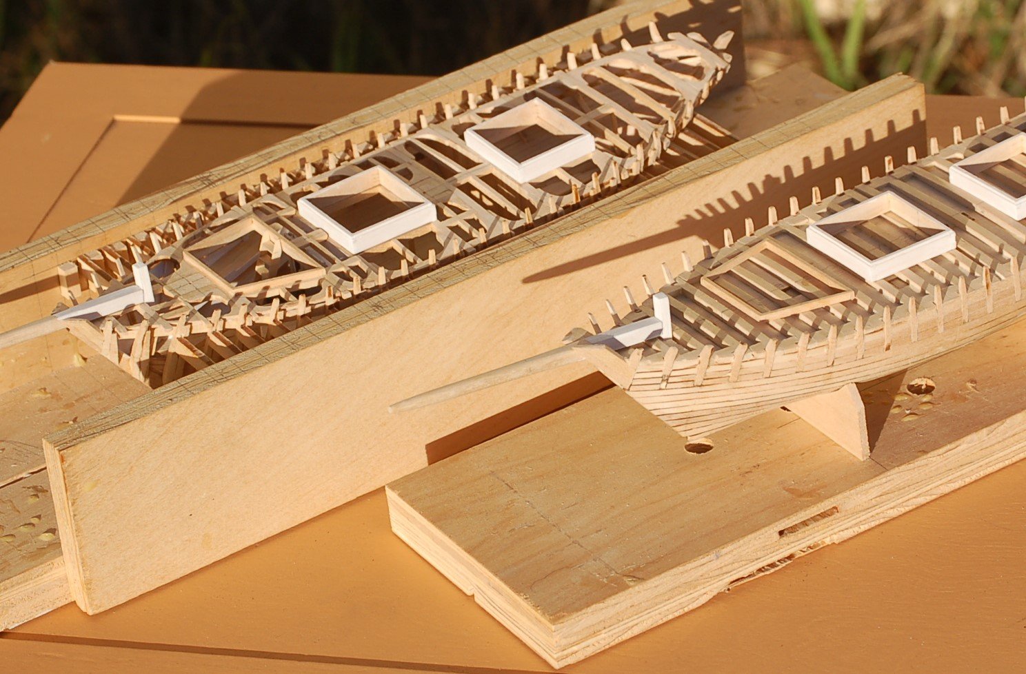
The hatches are the same size and interchangeable for both vessels but are marked “F” and “A” for fore and aft since each Dove has two different hatch sizes. Finally, each received a splash of white paint.
Here the hatches are seen sitting in place on the Doves. You can see that I’v nearly finished the deck framing at this point.
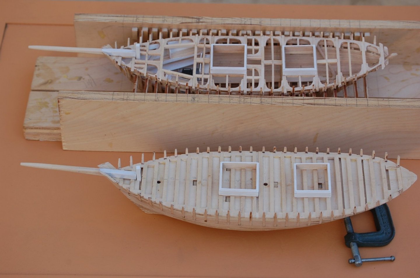
Figure 10‑4 - Two Doves, Two Hatches Each
The clamp holds the solid hull Dove on an even keel for its photo session.
Cabin Trunk
Next, I attacked the cabin trunk. The trunk is trapezoidal, will have a companion way offset to the starboard and four port holes. Its roof is curved and slopes toward the bow.
For portholes I have drilled out a piece of brass tubing to get thinner edges then sliced the tube into thin rings. As you can see, the cutting didn’t go too well and a bit of reworking will be needed. The ends of the trunk walls have been worked into dovetails which reflect the angle that the sides will meet. The fore and aft ends have their tops radiused to define the roof and holes to receive the port holes are drilled into the trunk sides. Finally, port holes are epoxied into the trunk sides.
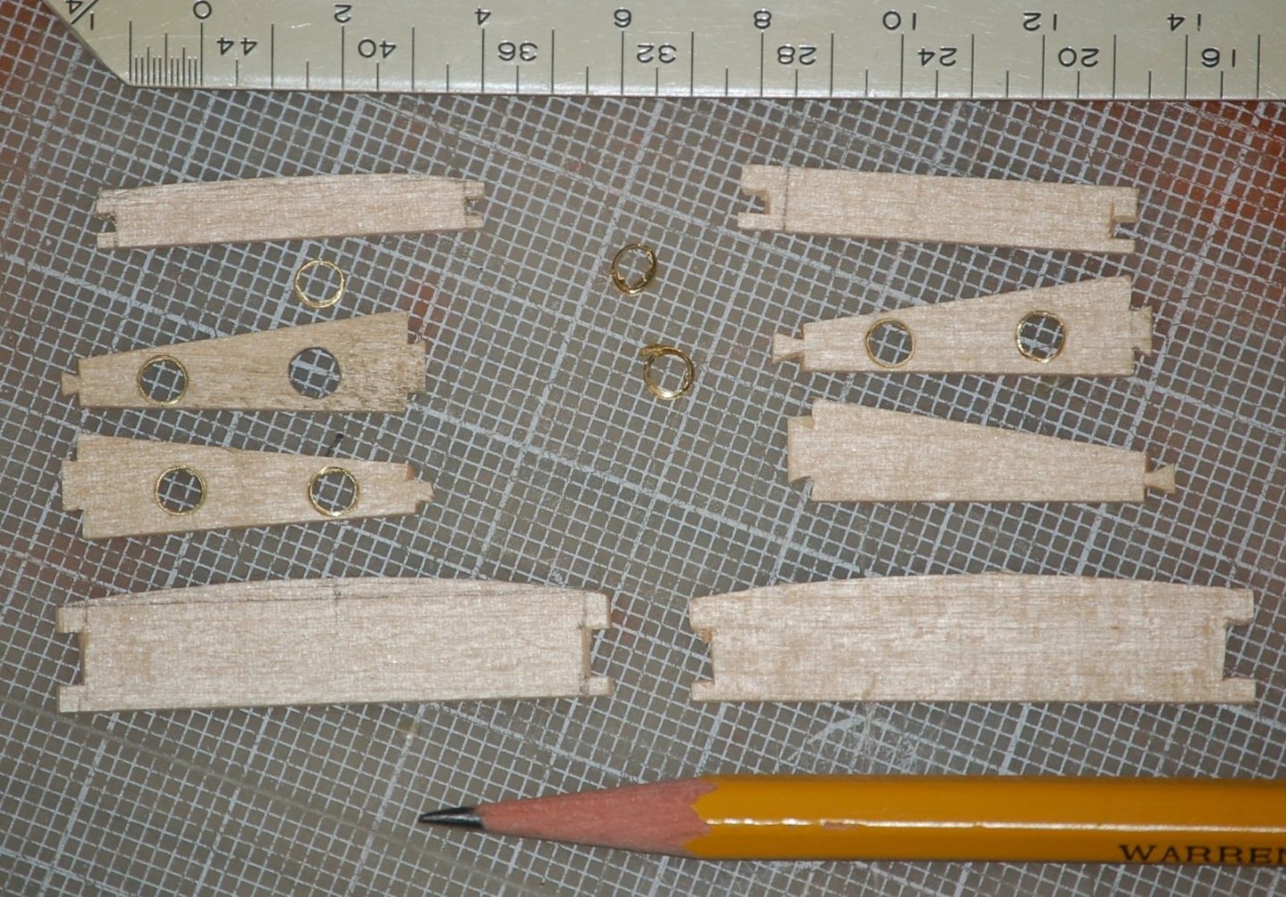
Figure 10‑5 - Trunk Sides
The companion way will be worked into the aft side after preliminary assembly.
The next steps adding roof and companion way framing. Curved beams reflect the curvature of the roof and block out space for the companion way. Like almost everything else about the Dove, even at quarter scale there are lots of small bits to be made and assembled.

Figure 10‑6 - Trunk Glued Up
The Trunk sits on a sill which will be let into the deck. Here you see the sill in place on the deck framing of both the framed and the solid hull versions of the Dove. In the framed version, I want to be able to have at least a minimal view down into the furnished cabin. The top end of the cabin ladder will attach to the sill once fixed in place.

Figure 10‑7 - Cabin Sill Located on the Deck
Fitting the trunk onto its sill. The drop-down portion of the companion way has been started now but it too will be left open. In addition, as part of my effort to preserve the ability to see as much of the cabin interior as possible, only starboard half the cabin roof will be planked.
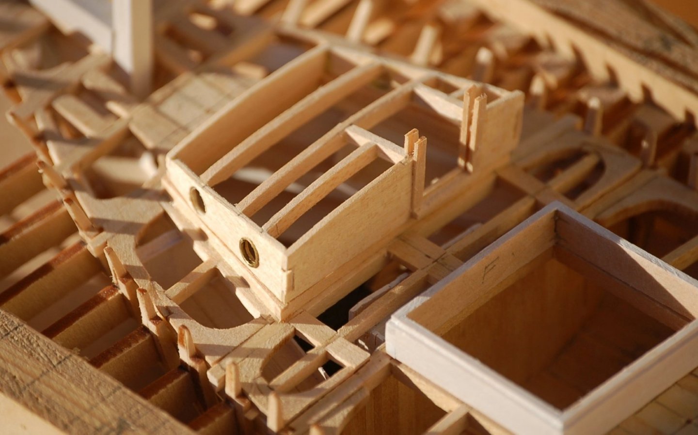
Figure 10‑8 - Cabin Atop its Sill
The break in the deck framing just forward of the fore hatch indicates that the framing in this area is still not glued in place. Next time you see it it will be glued down and deck planking underway.
Thanks for visiting
- Mirabell61, GrandpaPhil, Jond and 2 others
-
5
-
I'll jump on this train as well. Also a lover of Schooners I'll follow your work with interest.
Good luck with your project.
-
Fitting Out the Framed Dove – Below Deck (Part 2)
Work on the framed Dove has continued below deck. This post concentrates on the cabin interior and starting main deck framing.
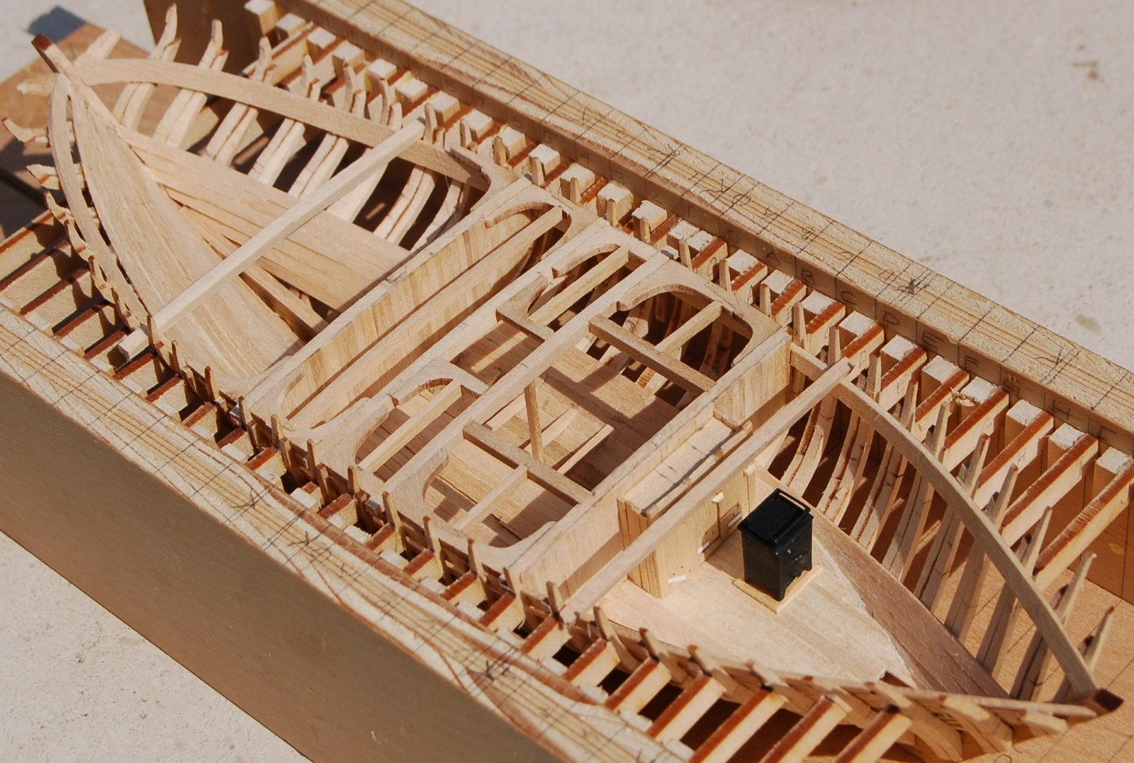
In the first image both bulkheads are now complete, the flooring for the fore hold has been framed and partially installed and additional main deck framing and knees added.
I’m still not sure about the long-term wisdom of the tabs connecting the Dove’s ribs to my little erection box but so far, they have afforded me a strong rigid frame against which to work and flex the interior planking. I'm hoping that once cut free from the jig, the interior work will return the favor and provide a strong base against which to apply the exterior finishes.

Figure 9‑10 - Forward Hold Fitted Out
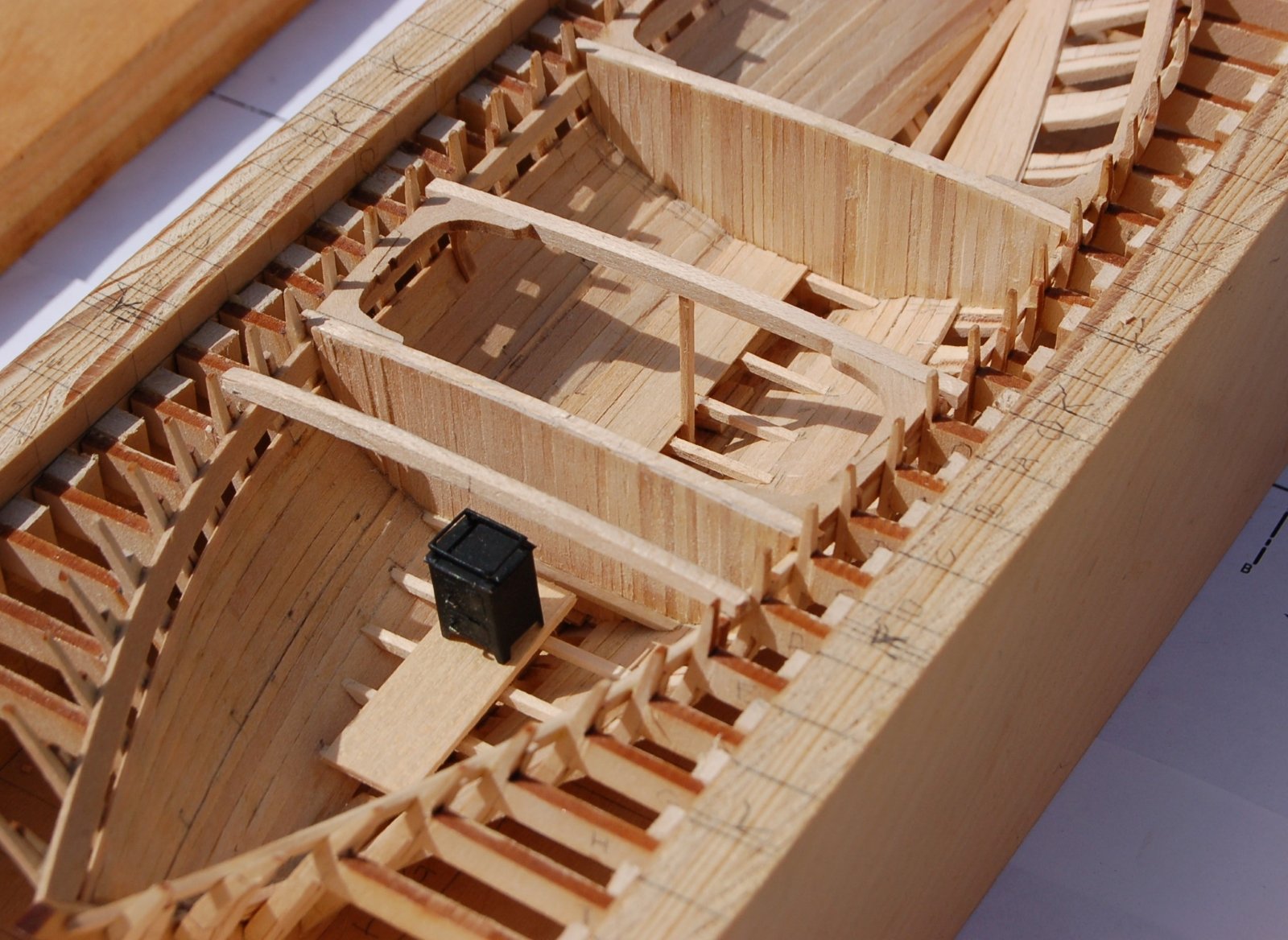
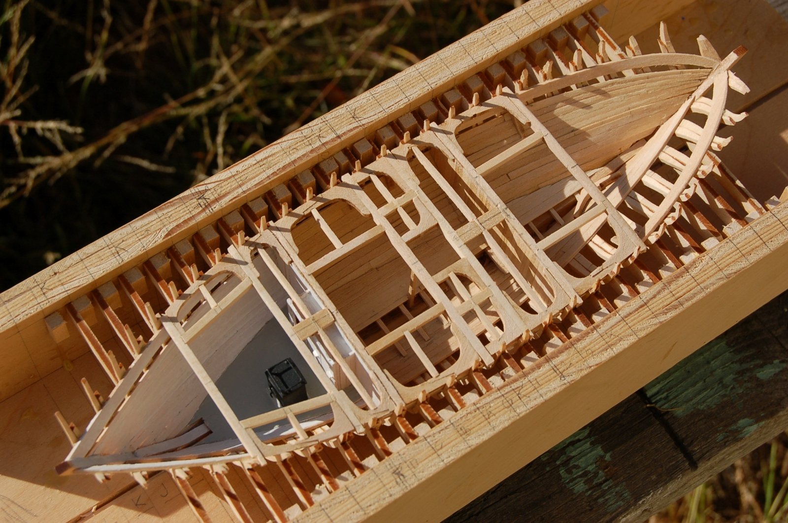
In the following image the main deck framing has been completed above the fore hold including the framing around the forward hatch and supporting the main mast.
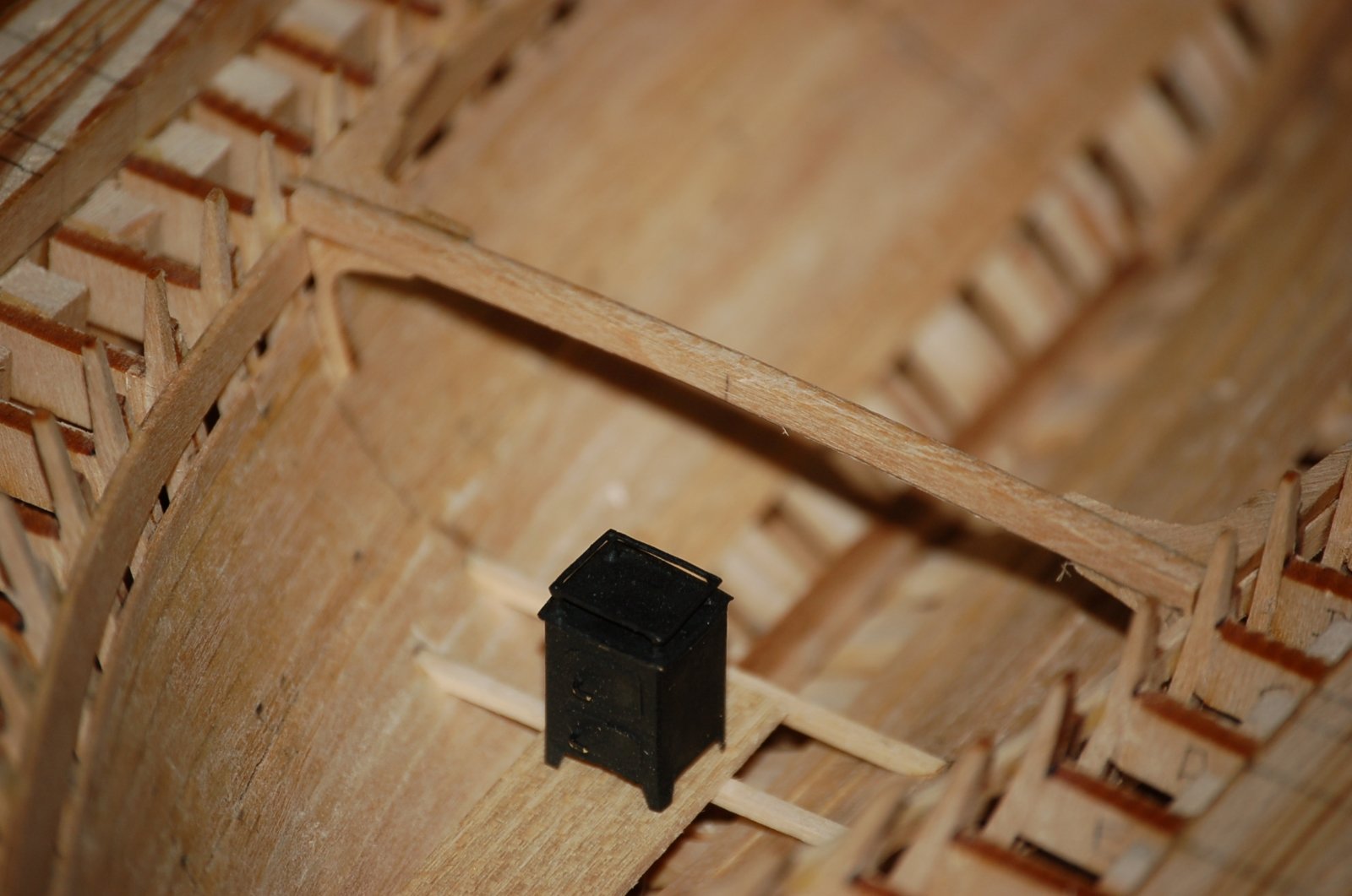
In the cabin area there is now a complete floor, a pad for the stove and three small lockers for the crew.

Figure 9‑11 - Cabin Underway, Fore Hold Near Complete
The main deck framing in this image now encompasses the opening for the cabin trunk and the hatch accessing the aft hold. There are still a fair number of beams, knees and secondary framing material to go but day to day it looks more complete.
I’ve also taken a moment to paint the cabin interior and set the stove permanently in place.

Figure 9‑12 - Advancing Deck Framing
Shown in this image is the complete main deck framing in the bow. Also fitted is the kingpost (painted white) which will support the bowsprit and windlass ratchet pawl. Since I have more work to go the deck framing ahead of the cabin bulkhead is glued into a sub assembly but is removable and not yet glued in place above the cabin.
While you now see colors applied to this model, I’ve decided that as it will be presented partially unplanked that it will be shown as if still under construction. As such the application of color will be limited to areas that might have been painted at such a point in construction. Color will also be used to draw the eye to features such as the partially covered cabin interior. In general, I will avoid strong colors on this model.

Figure 9‑13 - Deck Framing Above Cabin
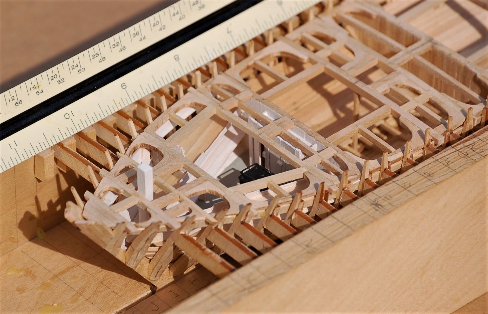
Progress in modeling the cabin is shown in this image. In it, you can see benches and four upper-level berths. Also included are two pairs of hanging knees which will support the deck beams above. The knight head can be seen as it penetrates the berths on its way to the keel. At the extreme bow hawse timbers have been worked into the framing and hook applied between the clamps. Bracing diagonals have also been added in the bow. Similar diagonal bracing will be fitted in the stern.
This is a small cabin and likely crowded and uncomfortable for the Dove’s crew but I’m not yet finished adding furnishings down here. I guess it was tight and intimate but better than being in the weather when the little stove was going.
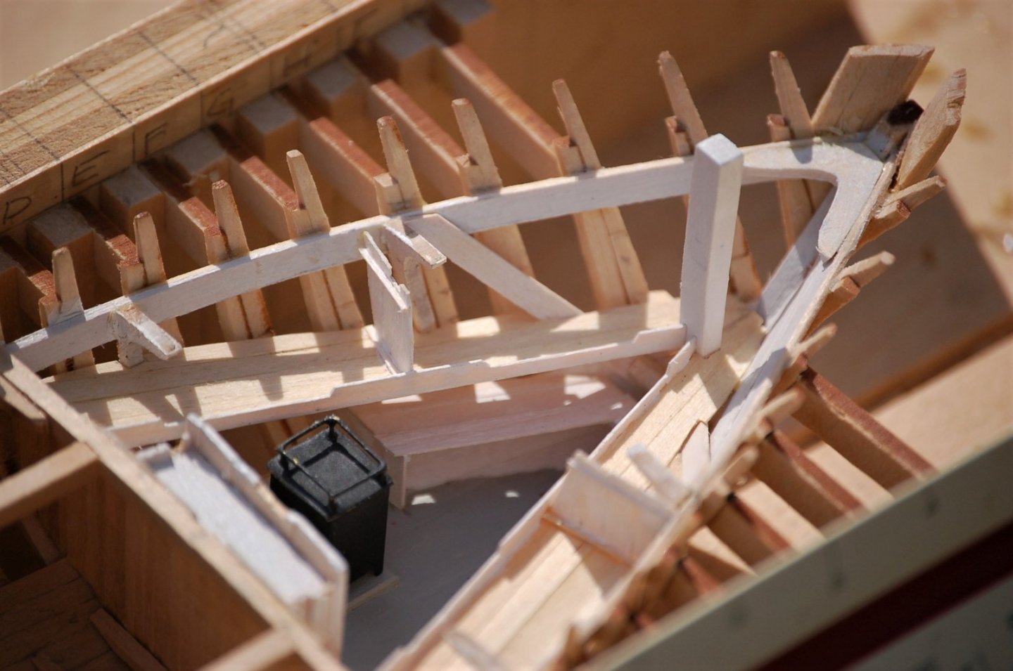
Figure 9‑14 - Cabin Furnishings
Here are the final fittings intended for inside the cabin. The mandatory ships ladder a small table and the stove pipe. Like most of my piecework I’ve attempted to make the wood components of material whose thickness is as close to scale as possible. Even at the relatively large quarter scale the cabin fittings take on a fairly delicate look and yes, they are pretty fragile.
I’ll need to drill a hole in the stove to receive the stove pipe.
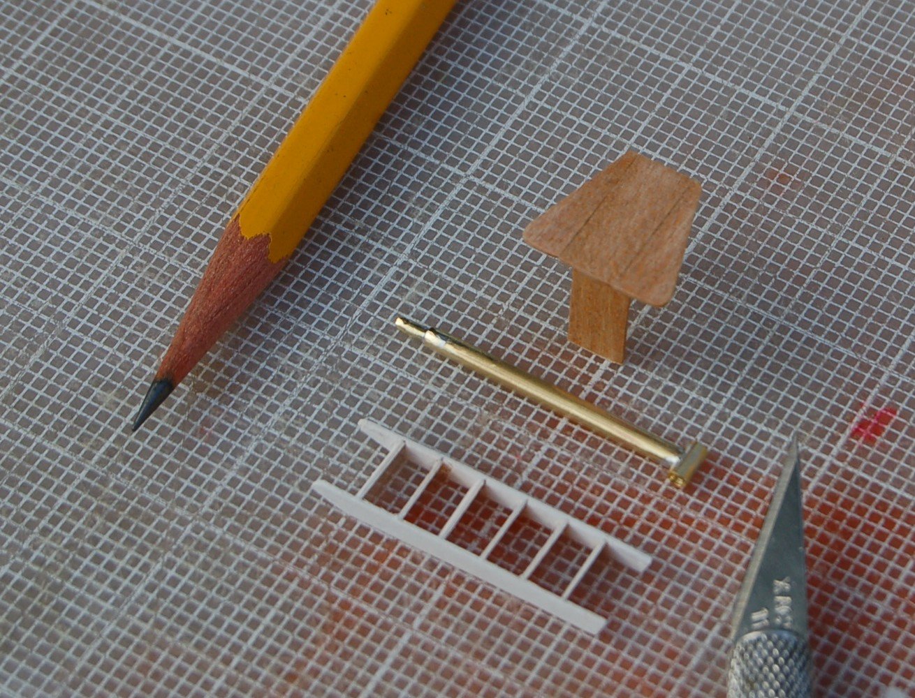
Figure 9‑15 - Cabin Furnishings
At this point the work on the cabin is nearly complete. The table is in place, the ladder sits approximately in place and the stove pipe is tacked in place still lacking a coat of paint. Adding to the general congestion of the tiny cabin is the fore mast which passes between the forward berths and the table. There just wasn’t any spare room in here. In the next chapter we will look at finishing the deck, railings and work above the deck.
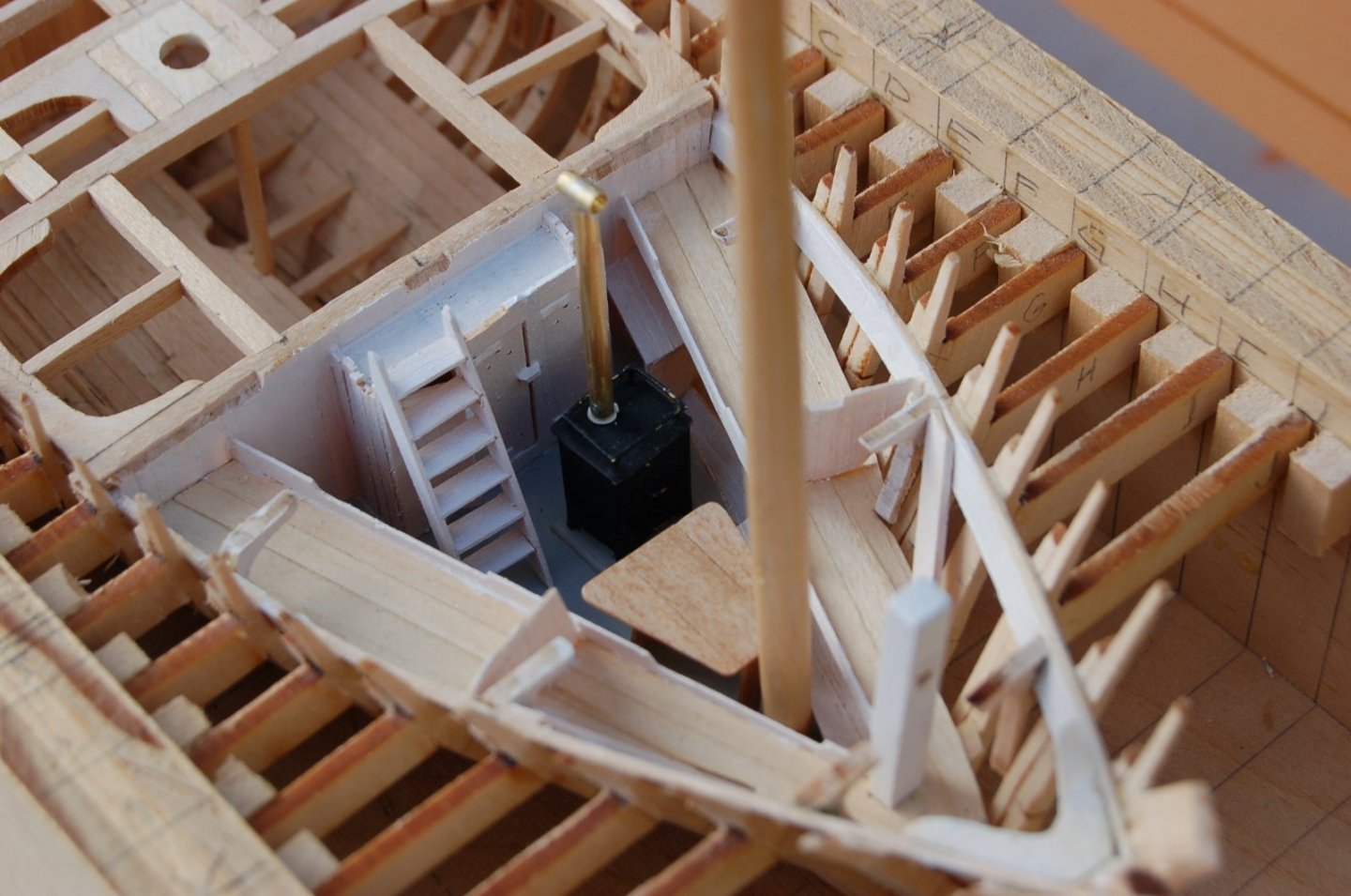
Figure 9‑16 - Finishing the Cabin
Still more to come - Thanks For looking
- gsdpic, Wintergreen, GrandpaPhil and 1 other
-
4
-
Fitting Out the Framed Dove – Below Deck
In this section I’ll discuss the work on the Framed Dove that went below deck. This includes the framing, planking, floors, cabin accommodations and the two holds.
The work starts with the bilge and upper clamps and the lighter ceiling applied to the inside of the Dove’s ribs.
Much as they do on the actual ship, the clamps (heavy planks attached to the insides of the ribs running the length of the hull) unite the independent ribs into a stiffer structure. First applied are the bilge clamps about midway up the ribs near the “turn of the bilge”. I’m using thumbscrews on carriage bolts to clamp the clamps.
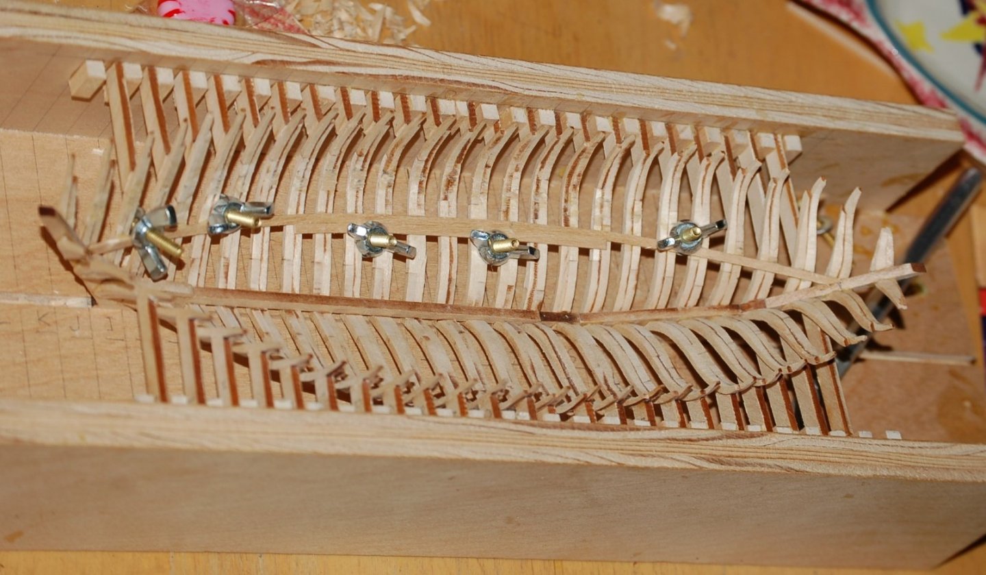
Figure 9‑1 - Fitting the Bilge Clamps
On the Dove the bilge clamps consist of three 2 ½ inch by 5 inch planks. Below the last Bilge Clamps are being applied with whatever clamping devise was close at hand. I should note that in reviewing the Chapelle plans after the installation was complete that my clamps are applied a bit low on the ribs. They would have been more accurately applied if the second and third plank were applied above the first rather than below.
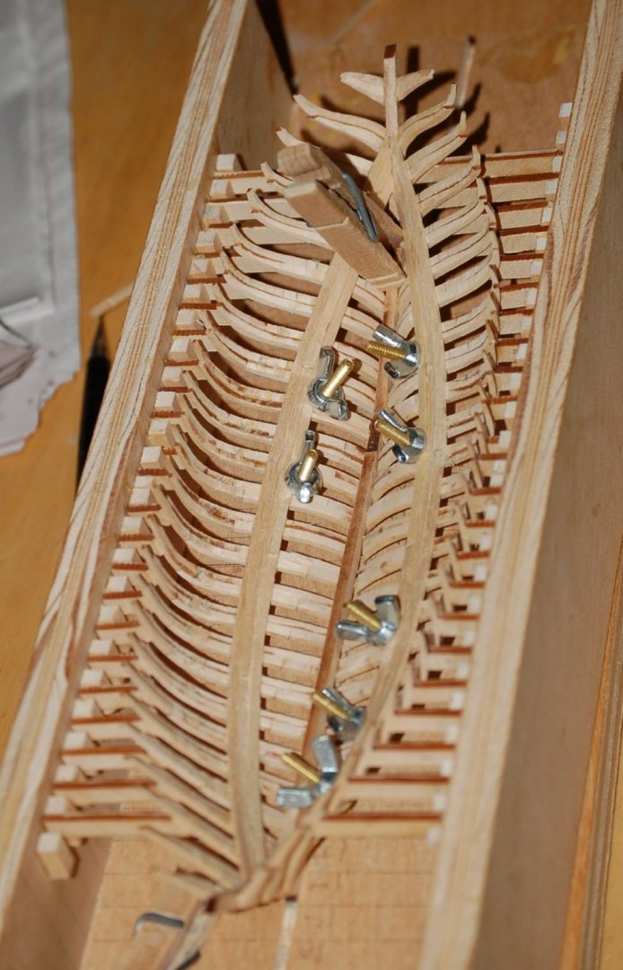
Figure 9‑2 - Nearly finished Bilge Clamps
A second clamp is applied to the ribs just below the deck beams. This consisted of a single heavier 3 inch by 7 inch plank. These clamps proved a bit of a wrestling match to flex into place but now that they are there, it’s another big step toward making the Dove look like a ship. So far, my little model is proving to be quite robust taking a lot of pushing and pulling as I flex the clamps into place without noticeably deforming.
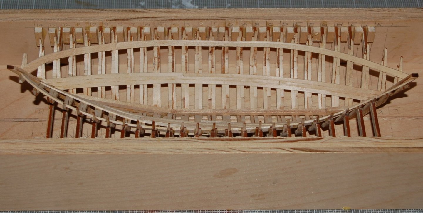
Figure 9‑3 - Upper Clamps Installed
After the clamps were installed, I took a bit of a break from wood work to model the Dove’s stove. Executed in sheet brass and wire the parts of this tiny appliance were not terribly neatly soldered together. In the image below the completed stove (minus stove pipe) sits on a dime. Over the weeks and months to follow my soldering skill will continue to improve and for now I can comfort myself with the knowledge that this rough effort at modeling the stove will be painted black and buried deep inside the model.
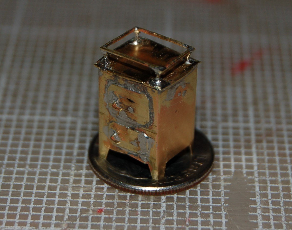
Figure 9‑4 - The Dove's Stove
The next modeling tasks consisted of starting to install the ceiling and cabin floor.
In the dove the ceiling consisted of 1 ½ inches thick planking that ran from the keelson to just below the upper clamp where an air gap was left to allow ventilation of the spaces between the ribs. For my model, since I intend to do a fair amount of interior modeling, I have decided to leave gaps in the ceiling and planking intended to allow views into the completed model. The Starboard side will be completely planked (or ceiled?) while the vision gap will appear on the port side.
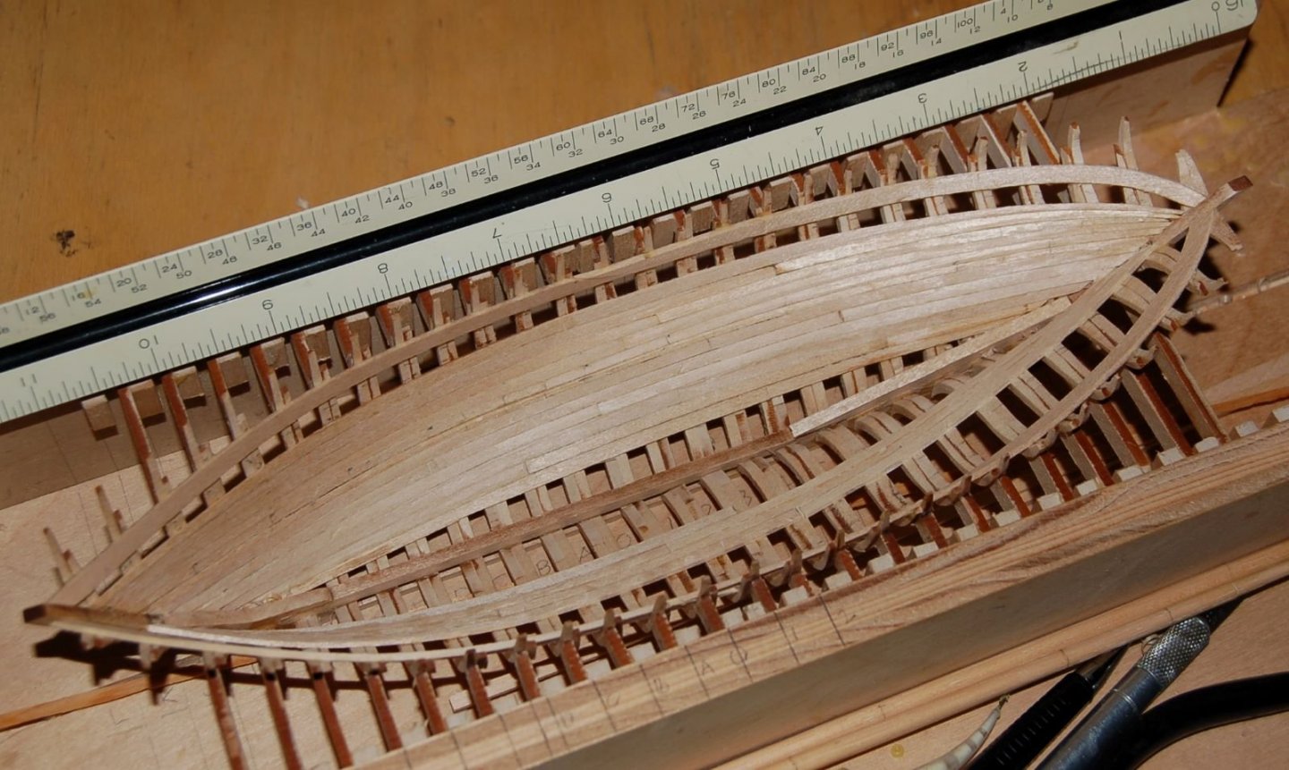
Figure 9‑5 - Ceiling Planking Nearly Complete
In the following image the ceiling planks have been installed but have been left off between the clamps on the port side. Below the bilge clamps the cabin floor beams are being placed. The small gantry like device was used to assure the level application of the beams.
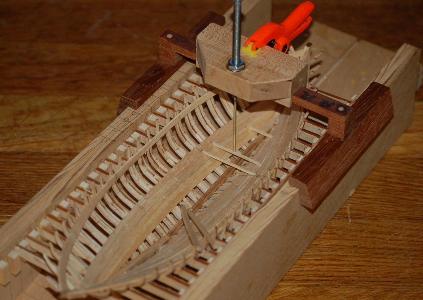
Figure 9‑6 - Installing the Cabin Floor Beams
Once again, I’ve returned to the laser cutter to cut the various knees and hooks needed to frame the Dove’s deck. There are a bunch of them and they can get pretty extreme near the Dove’s ends. The knees with one curved leg are fitted to the hull shape as hanging knees. The knees in the plane of the deck have stepped legs to lap adjacent knees and in some cases notches to receive a secondary beam.
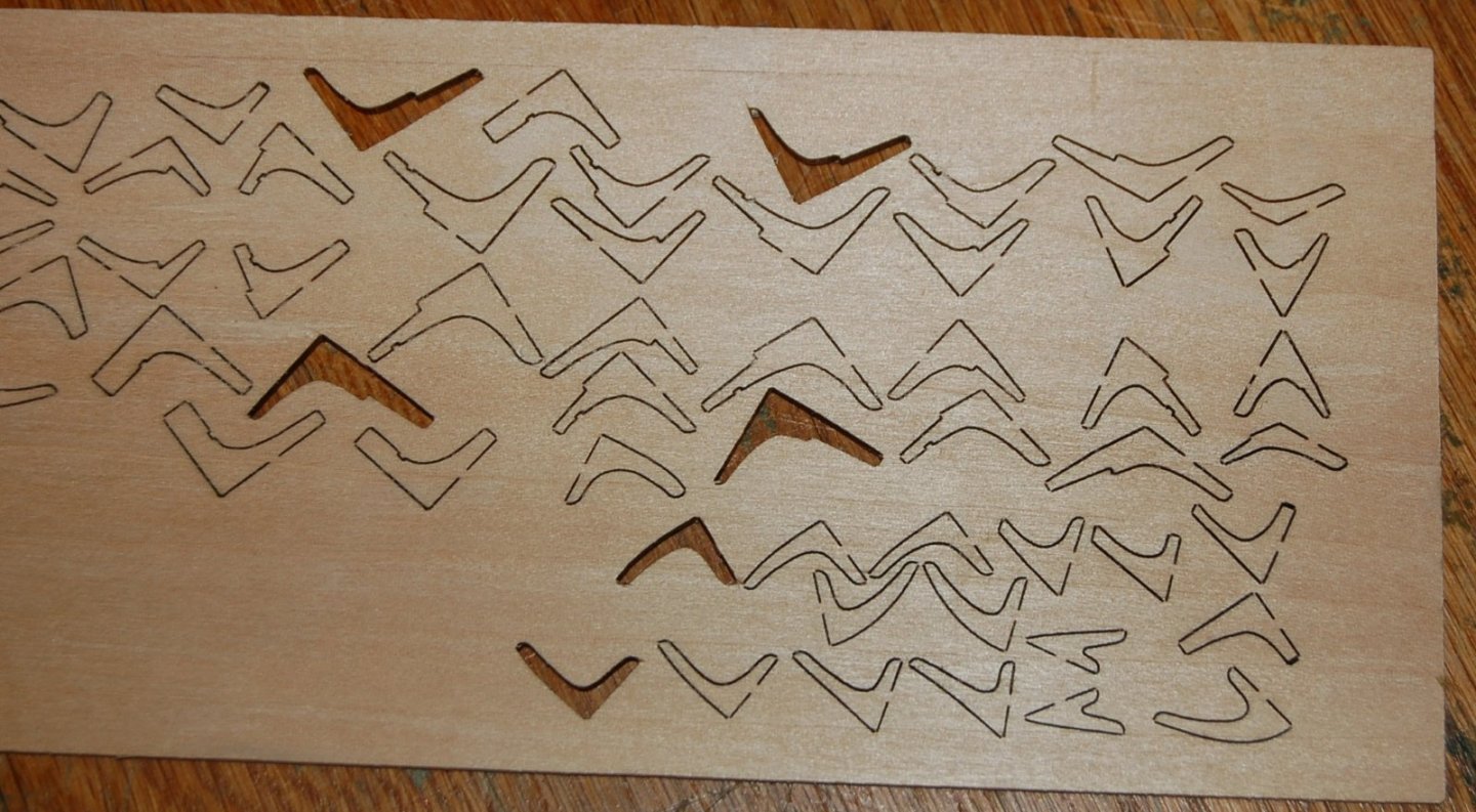
Figure 9‑8 - Freshly Cut Knees
The Dove’s cabin was in the bow with two holds to the aft. Between the cabin and the first hold was a bulkhead running from the adjacent deck beam to the ceiling and floor below. In the image below the little stove sits on test floor boards and the main deck beam which will support the bulkhead has been added above. It’s braced in two directions with knees and will get additional support before I’m done.
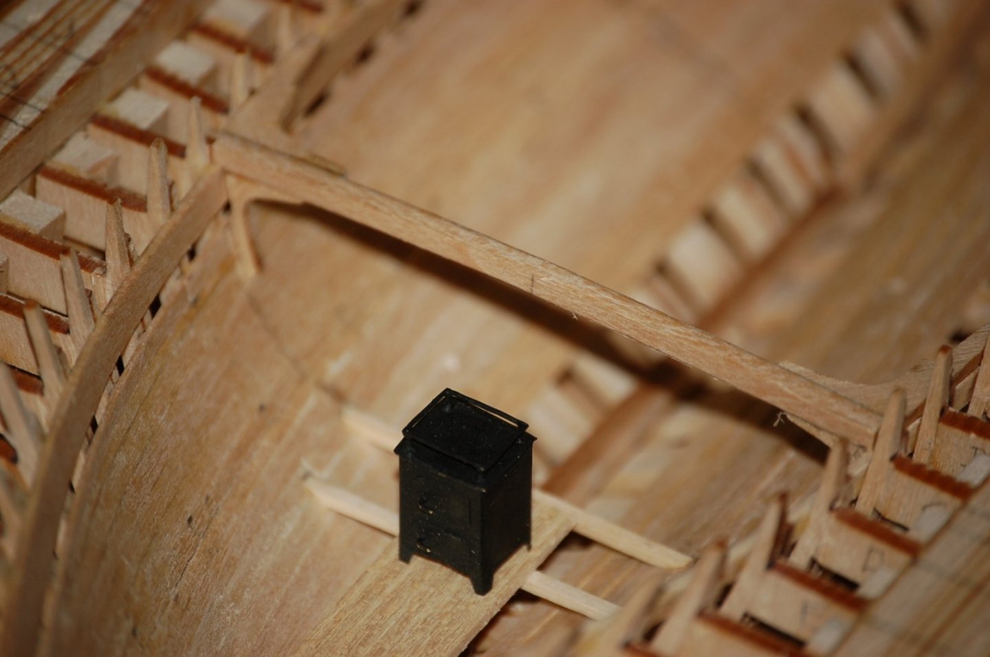
Figure 9‑7 - First Deck Beam
Thanks for looking in - More in a week or so
- Jond, GrandpaPhil, Wintergreen and 2 others
-
5
-
Building a Bread-and-Butter Solid Hull
Now that the Framed Dove is underway it’s time to start stacking and gluing on the solid hull Dove. With a lot fewer parts this will be a much faster start. With the framed model when I laser cut the parts in many cases I left small tabs to retain the pieces in the wood sheet. With the bread and butter lifts I didn’t bother and simply cut them out. They were big enough that I had no worry about losing them.

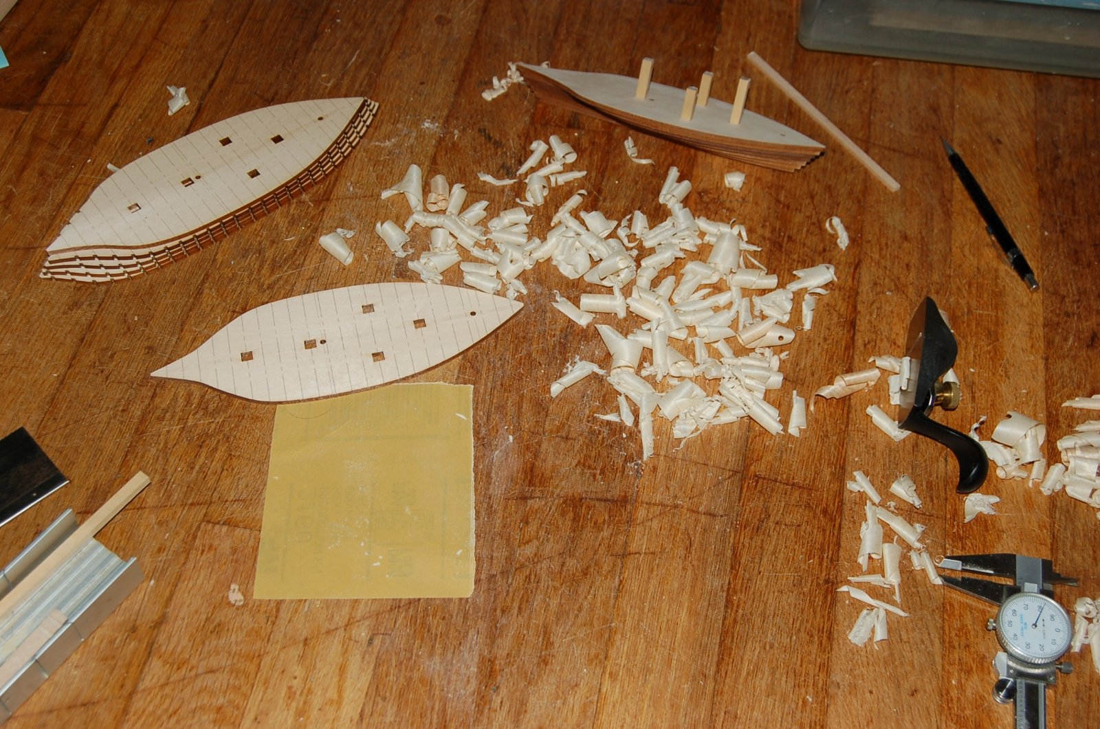
Figure 8‑1 - Laser Cut Solid Hull Lifts
With parts in hand one of the first things I did was stack them up and check the overall dimension. It was close but not as close as I had hoped. Investigation showed that my 1/8” sheets were in fact only near 1/8”. Several were thicker than advertised and when more than one lift came from the same sheet it doubled the error.
This set up a session of measuring, plaining, sanding and measuring again. It really didn’t take all that long to get them comfortably in tolerance (fortunately none of the sheets was significantly less than 1/8”.

Figure 8‑2 - Shaving the Lifts to Measured Thickness
With the thickness adjustment in hand, I restacked my lifts and was more than a bit pleased with the result. The cuts looked accurate, the registration pin block outs lined up and the supportive line work showing stations and keel was quite legible.
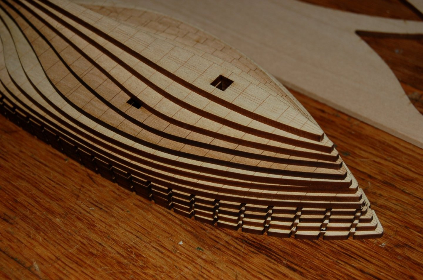
Figure 8‑3 - Lifts Ready to Glue
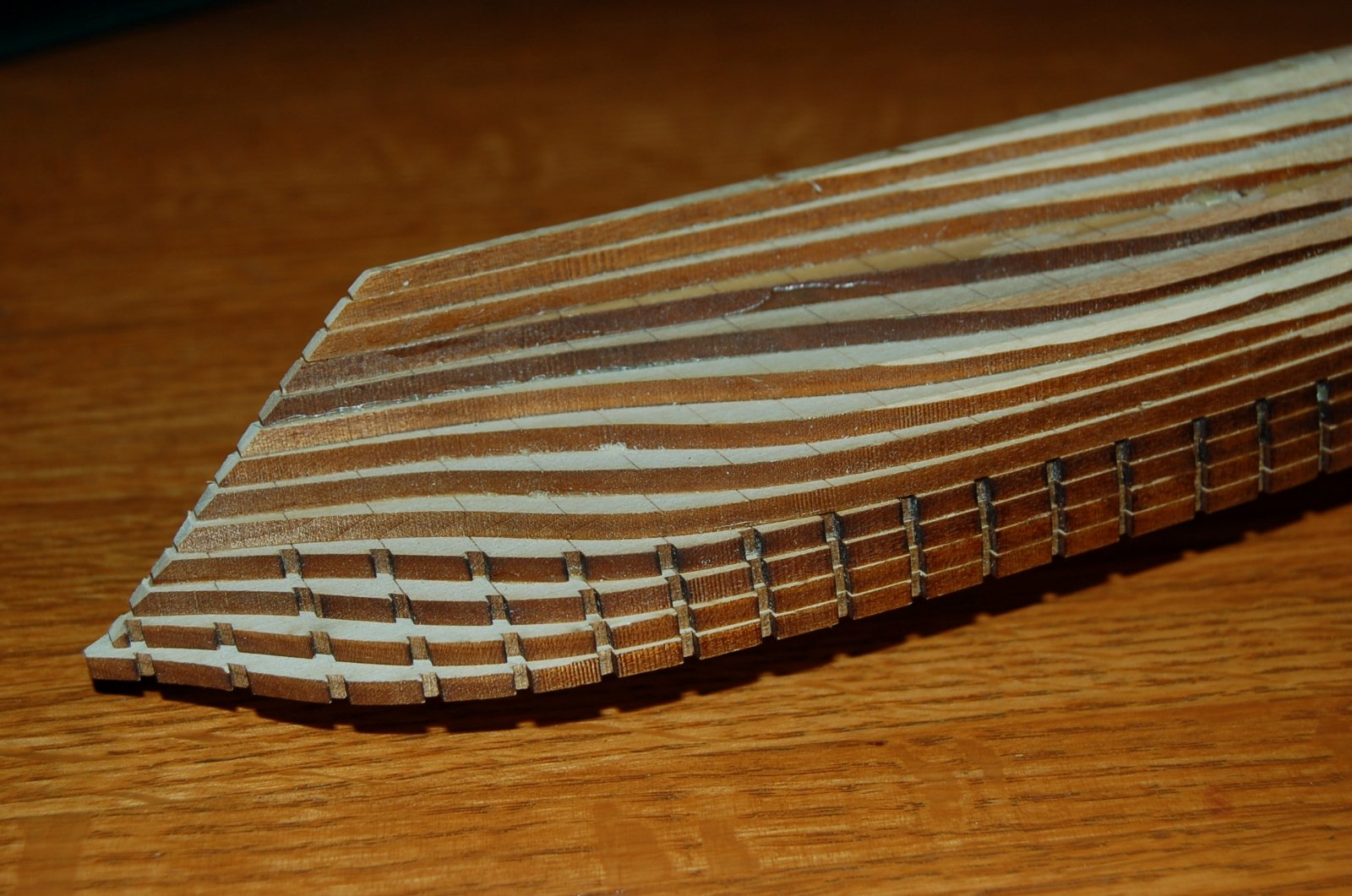
A generous application of carpenter’s glue between the sheets and with the ¼ inch by ¼ inch registration pins in place the gluing went quickly. The entire hull was clamped and let to set for a few days. Then the carving began. The intention was to simply remove the steps cutting away until the scorched line at the inside of each step appeared as a contour line for the nearly complete shape.

Figure 8‑4 - Shaving the Hull to Shape Begins
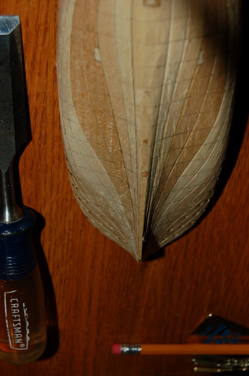
My tool of preference for the initial (and the bulk of the shaping) was a simple sharp chisel. It proved easy to grip and work against the hull. Typically, I worked from the widest beam at station -0- toward the ends and avoided working against the grain. Undoubtedly the sharp double end form of the Dove’s hull avoided the cross-grain work that might occur in a vessel with bluffer, more rounded ends or with a complicated counter or transom so my work went quickly and didn’t require fancier carving tools.
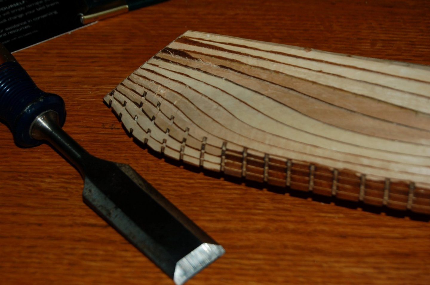
Figure 8‑5 - Shaving Nearing Completion
As I progressed, cutting away the scorched edges of the laser cut lifts, I was pleased to see that the station lines burned into the face of each lift remained visible. This visibility allowed me to sketch the station lines on the evolving hull form and to better visualize the form it was taking.
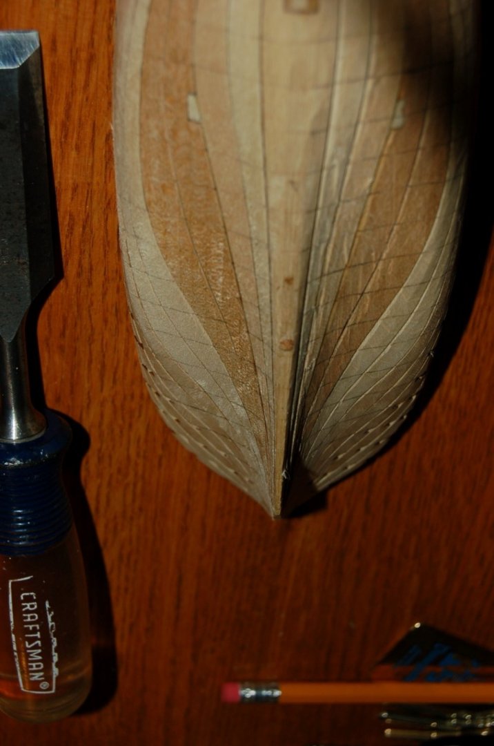
Figure 8‑6 - Chisel Work Completed
In the image below, taken after the final sanding you can still see the brown ticks from the laser etched station lines remaining remain visible documenting the lines on the carved and sanded surfaces. These will be important a little later when I begin to work on planking.
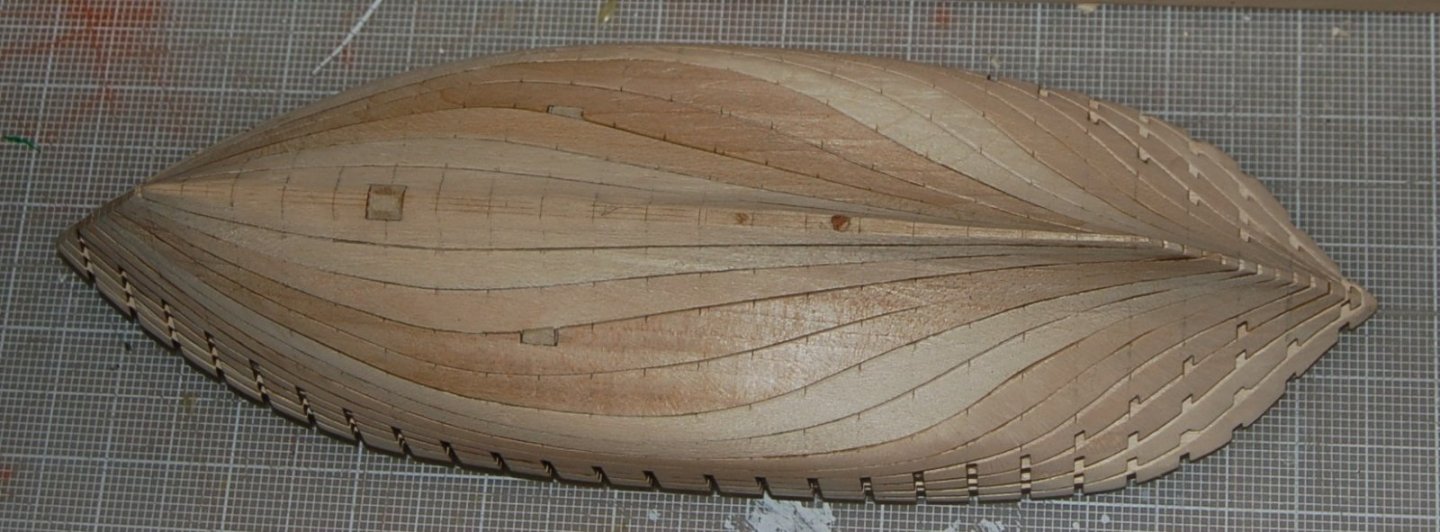
Figure 8‑7 - Sanded Hull
At this point, I’m quite pleased with the “ship shaped” result of the project and like the lines I’m seeing. She does flair out quite a bit at the stern from the keel to the deck creating a hull with a quite fine run below and a wide deck to work above and no need to work out a counter or transom.
I plotted sections at each station on stiff paper and cut them out to check the hull form. The laser ticked station marks made checking the final shape of the hull with paper templates much easier as there was little question about where exactly the template was to touch the hull. In general, the templates demonstrated little need to tweak the hull form.
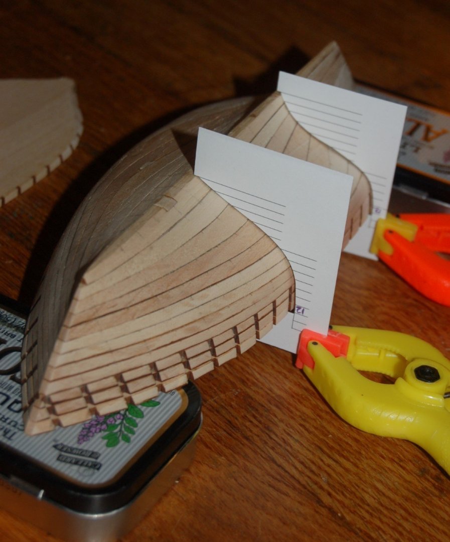
Figure 8‑8 - Checking the Dove's Lines
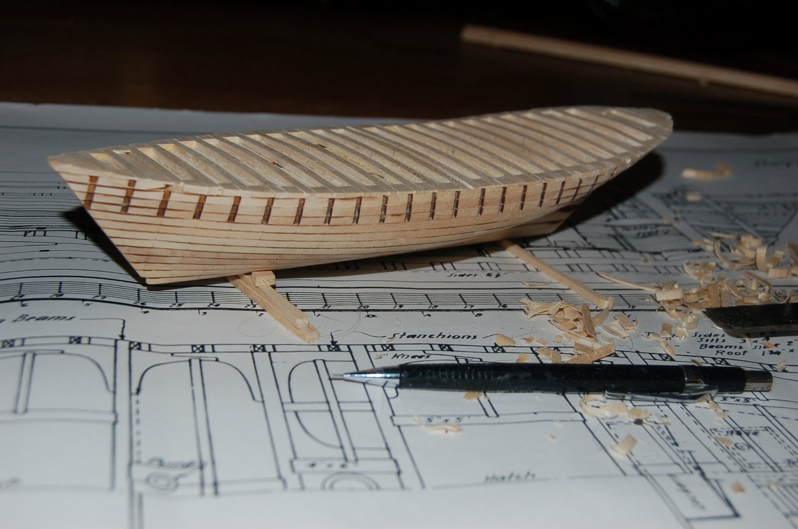
The top most lift was cut into three sections with only the forward most and aft most sections used in order to begin to represent the shear of the deck. The final profile of the deck was developed by adding precut curved pseudo deck beams. Small blocks were added at the edges of the hull to give a continuous edge along the plank shear. Once glued up a little sanding was all that was needed to get the hull in shape for the addition of the railing stanchions. In the figure below, the Dove is beginning to look quite “ship shaped.”
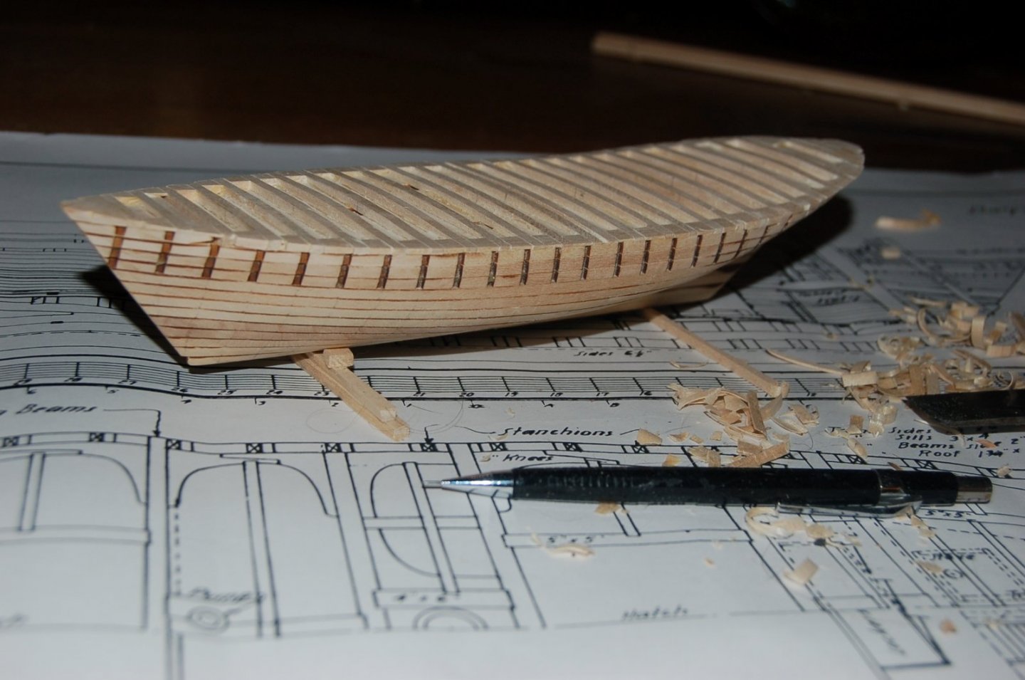
Figure 8‑9 - Deck Shaping Complete
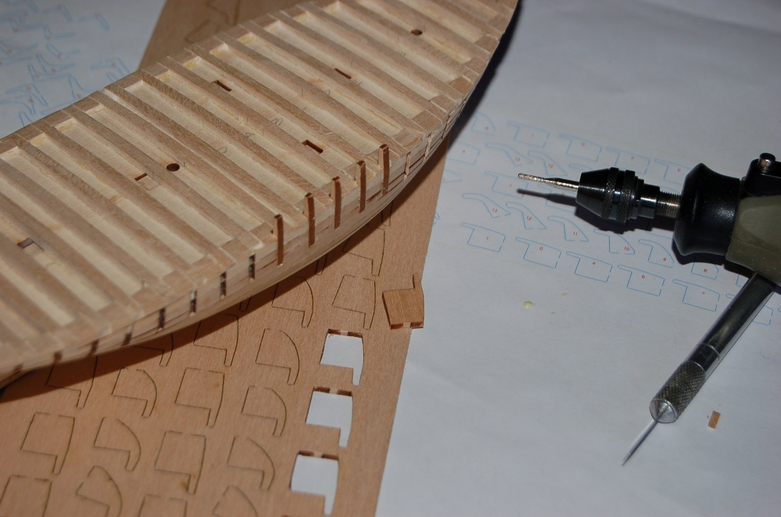
The final effort for this stage of the Solid hull is the attachment of the railing stanchions. Standing just 12 inches above the deck, the stanchions are pretty small but are an important part of the Dove’s looks. Tiny as they are, it’s also important that they be well attached. Once again, I returned to the laser cutter this time cutting out the stanchions which were just about the size of the final rib segment for the framed Dove’s ribs. Preparing for the cut, I copied the rib pieces, added a short tab to use to stabilize the stanchions and remembering that I would need a port and a starboard part I made two copies of each segment.
With cut stanchions in hand, I set about making their application to the model. Using a diamond abrasive bit in my rotary tool I deepened the cut in the precut grooves in the hull to form a continuous slot a bit deeper than the 1/8 inch initially burned into the upper lifts. The tabs on my new stanchions were about ½ inch by ½ inch but I ended up shaving most of the tabs off, before I glued each stanchion in place.

Figure 8‑10 - Cutting in Rail Stanchions
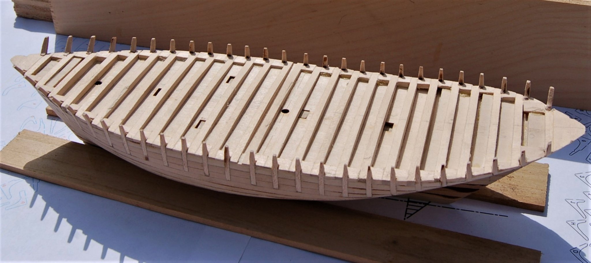
So here the Dove is with the hull pretty much blocked out and ready to receive planking and furnishings. The Stanchions are pretty strong but I would still knock off and replace a few of the more angled end pieces before I finished.
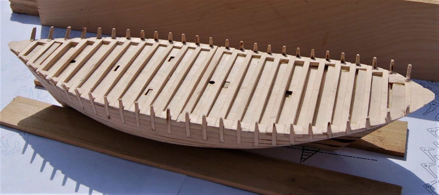
Figure 8‑11 - Rail Stanchions
Until next time, thanks for looking.
- Mirabell61, KeithAug, mtaylor and 3 others
-
6
-
1 Building a Framed Hull
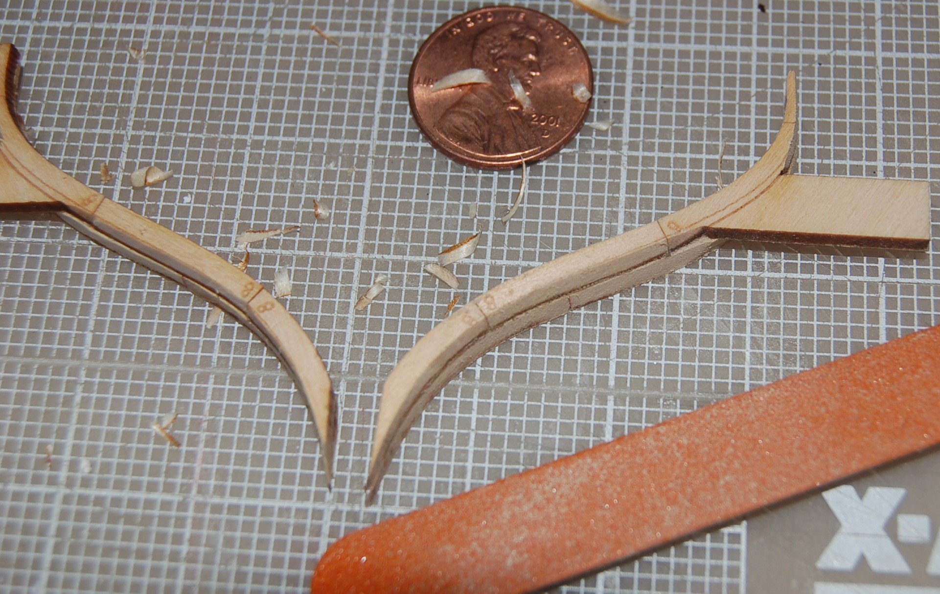
With dozens of little rib parts in hand I began the first assembly process, building up the individual ribs. At rib -0- both the fore and aft halves of the rib were pretty much the same profile. Forward of station -0- the smaller half of each rib would be its forward portion and of course aft of -0- it would be the after portion. Using the lines scribed on the larger side of the rib during the cutting process I began attaching the sections of the smaller side with glue.
Below are the parts used to make up the starboard portion of rib 8. Rib 8 is the first rib to attach to the face of the keel and deadwood rather than sit on the keel.
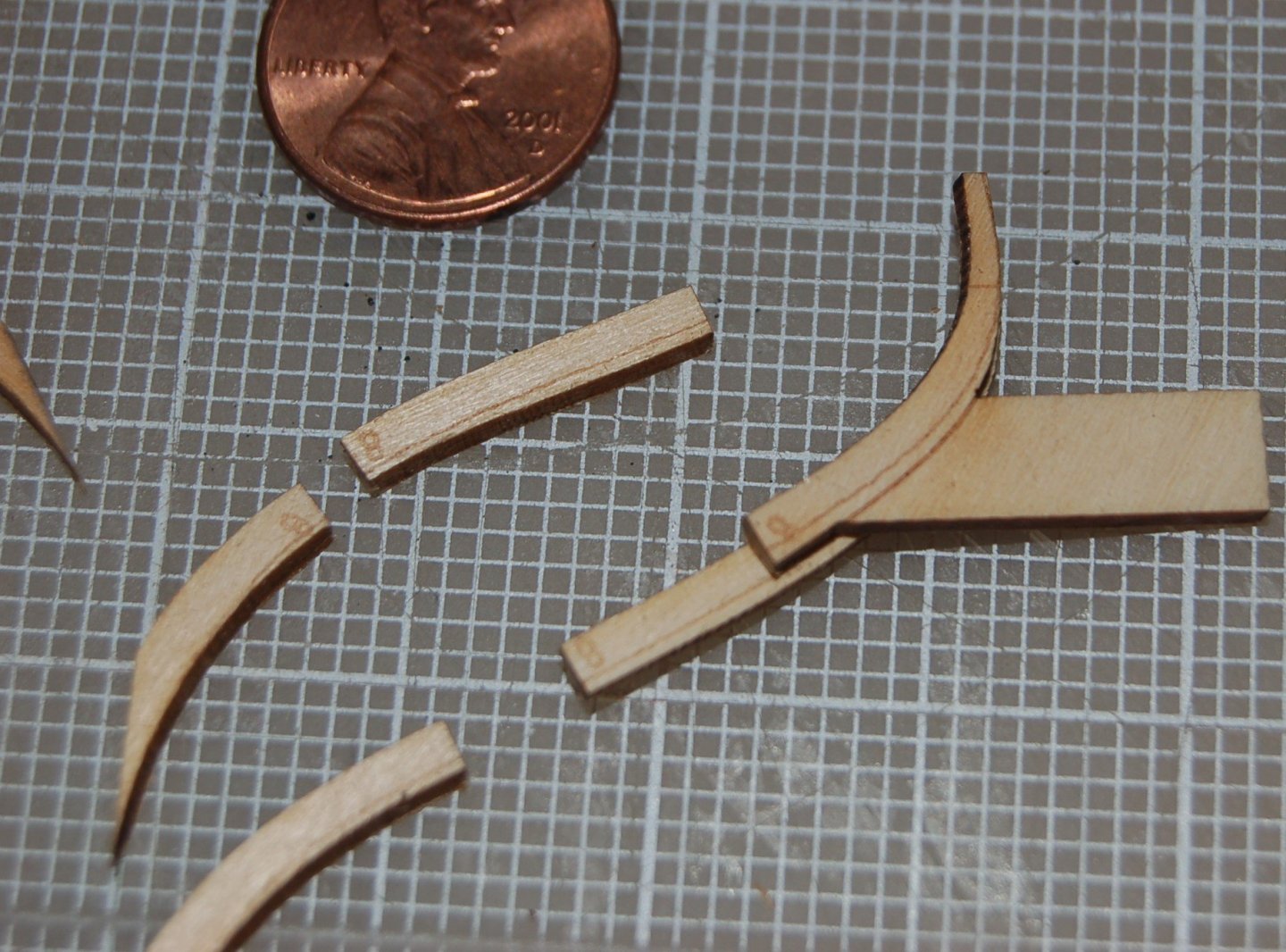
Figure 7‑1 - Setting out the Futtocks for Rib 8
With the Futtock’s now glued together I could start the initial fairing or shaping process. Using my hobby knife, I trimmed the outside face of the rib starting at the outside corner of the largest side, just meeting the point where the two segments met at the center and cutting down to the line scribed on the smallest face. While not scribed in the cutting process, the inside faces get the same treatment in preparation for the ceiling to come.
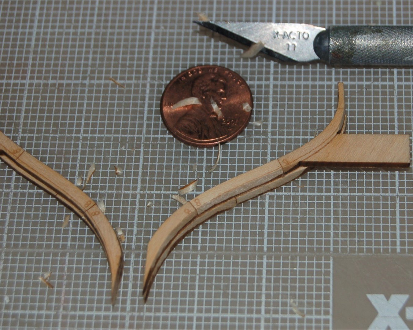
Figure 7‑2 - Shaving the Faces of Rib 8
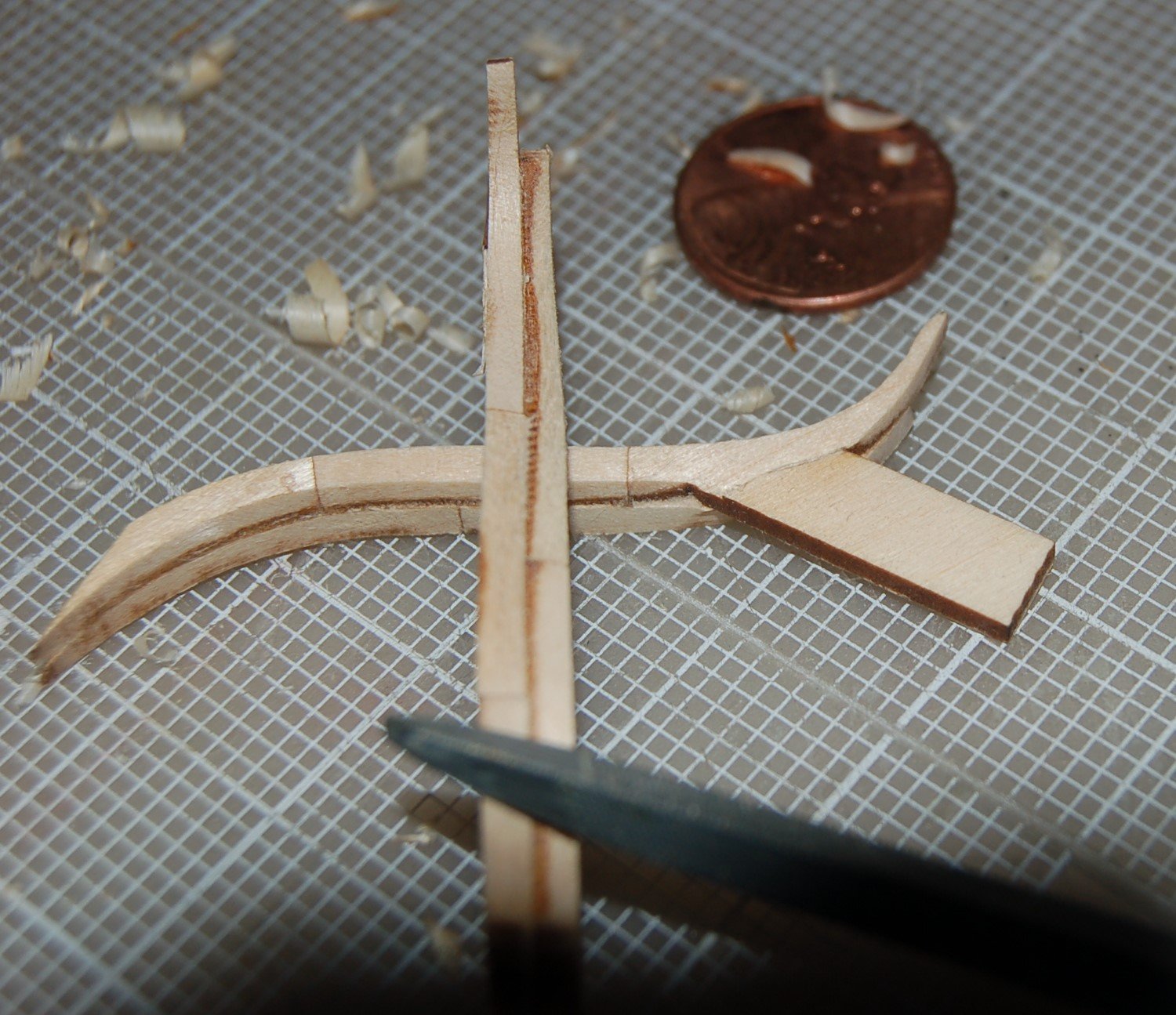
Finally, a few swipes with a sanding stick had the rib almost ready for planking. Note that the portion of the rib where the erecting tabs are connected will need fairing at a later date.

Figure 7‑3 - Sanding Rib 8
The rib also calls for a fore aft taper from keel to the top of the rail stanchion. This is accomplished by laying the rib flat on the cutting board and paring it with a sharp chisel until the desired thicknesses are achieved. Only 26 more ribs to go.

Figure 7‑4 - Fore - Aft Taper for Rib 8
Here I am setting up ribs d, e and f. These are three of the ribs that sit directly on the keel and are trapped by the keelson. “e” and ‘’f” have been glued up and the fairing process started on the starboard side of “f”. The tabs proved useful during this stage allowing me to clamp the rib down while the glue dried and to check the correct span and curvature of the assembly. I looked for each to be exactly four inches end of tab to end of tab.
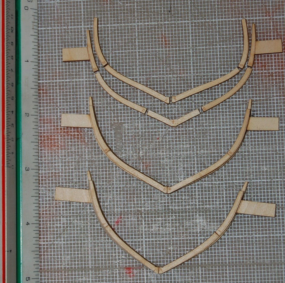
Figure 7‑5 - Additional Ribs Laid out
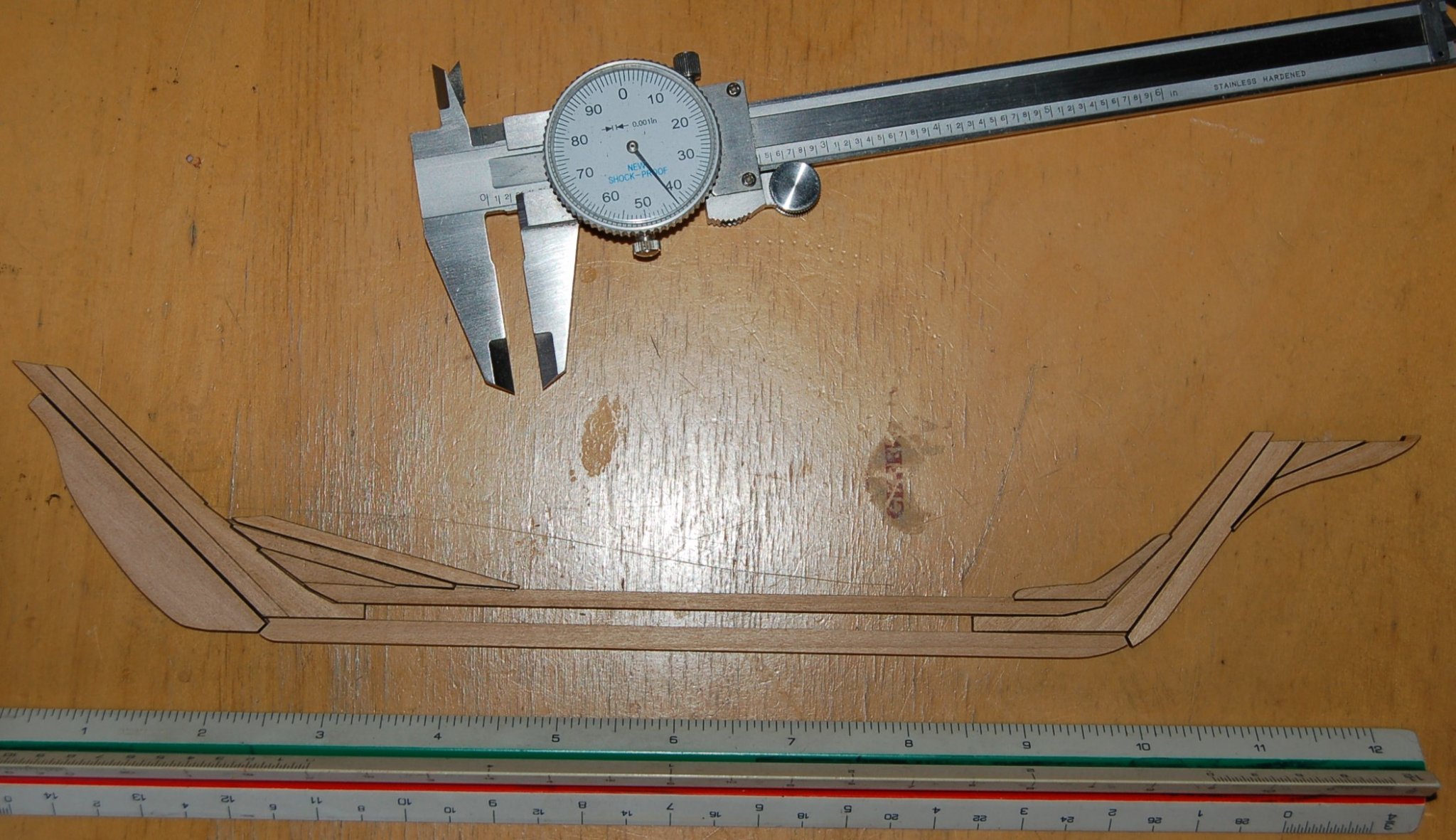
During breaks in my work on the Dove’s ribs, I worked on the keel and associated timbers including a blank for the rudder. In this case I basically traced the lines from scans of the Smithsonian drawings in my CAD software and sent them off to the laser cutter. In addition to the keel, I cut the keelson, the long timber above and parallel to the keel, the stem post and stern post, the stem post knee, the angled dead wood at the stern and finally two pieces of the cutwater which will give the Dove it’s graceful bow. The top piece of deadwood was cut short and would need to be redone. Other than that miss-step things went quite well. In this image you can get an initial idea of how big the Dove models will be, approximately 12 inches between perpendiculars. Even though the solid hull wouldn’t need the keelson and interior timbers I simply burned two sets in preparation for the solid hull to come.
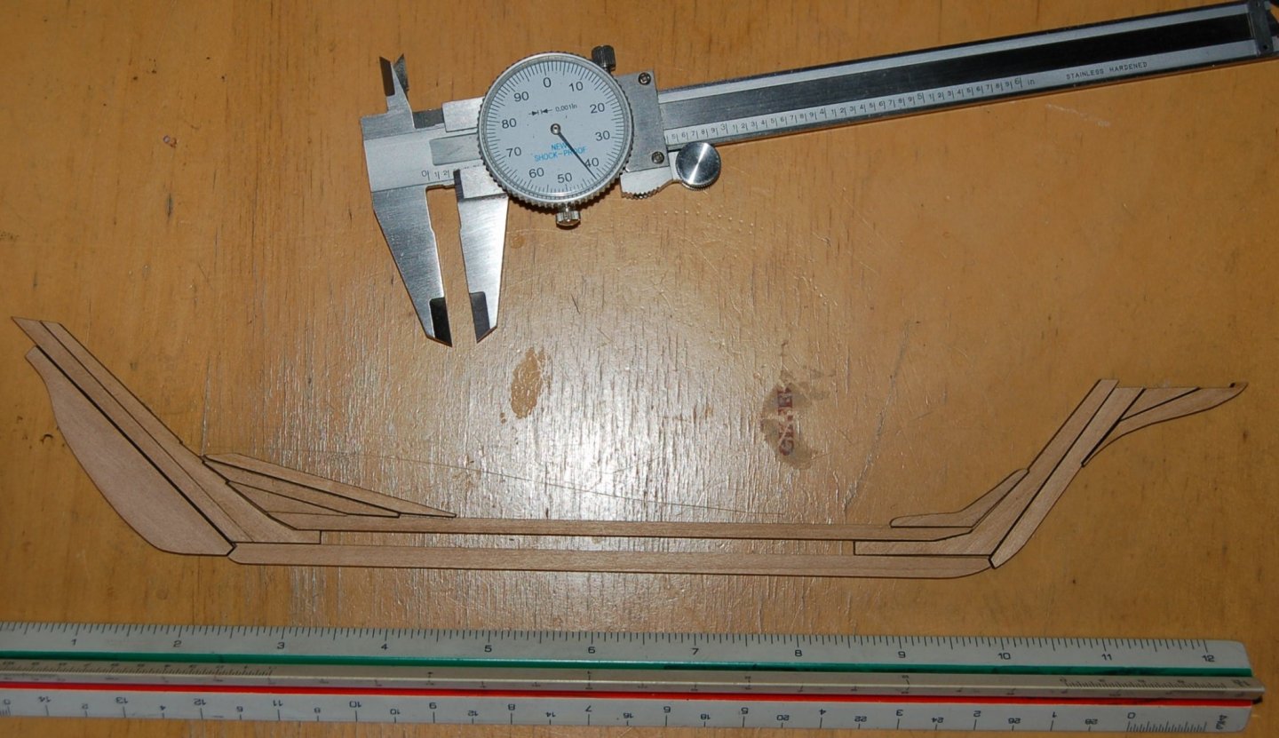
Figure 7‑6 - Laser Cut Keel Parts
Now it gets interesting. So far, I have been making tiny pieces, wishbone frames; fish shaped Lifts and spindly keels. I’ve reached the point where I can’t keep making pieces without attempting to put some of them together, I need to know if what I’ve planned will have any chance of working. It’s time to lay down the keel and start standing up frames.
To erect the framed Dove, I needed a wood jig or support system. This was made up from bits of scrap plywood. The base is approximately fourteen inches long and exactly four inches wide. A 1/4” kerf has been cut down the center of this piece to receive the Dove’s keel. Along this bottom I drafted lines at 3/8” spacing (18”s scale) and labeled them with the station numbers. After copying the station lines to the sides of the jig, they were screwed and glued to the base. The sides were also labeled with the station numbers and a horizontal pencil line indicating the height of the erection tabs.
With the erection jig assembled it was time to start building the Dove. The stem and stern posts were glued to the keel and the assembly set into the groove in the jig. The keel, stem and stern posts were also marked with the station points. Next short quarter inch square blocks were glued to the jig at the vertical station lines. Once everything was set a bit of glue was applied to the base of rib -0- as well as the ends of its two erection tabs and it was set on the keel. Two small wedges hold the rib in place while the glue sets. The Dove’s first rib has been installed and we’re underway.
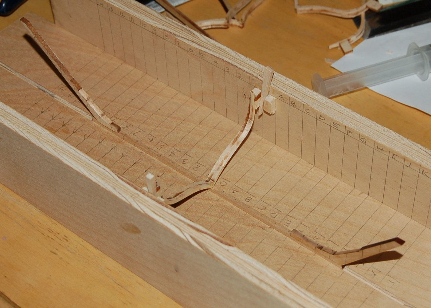
Figure 7‑7 - Keel and First Rib Set UP
Here more blocks are glued in place and ribs 1,-0- and “a” have been inserted gluing their bases to the keel their tabs to the adjacent blocks. The stem post (bow) is to the right and the stern post to the left. The stern post has an impressive rake.
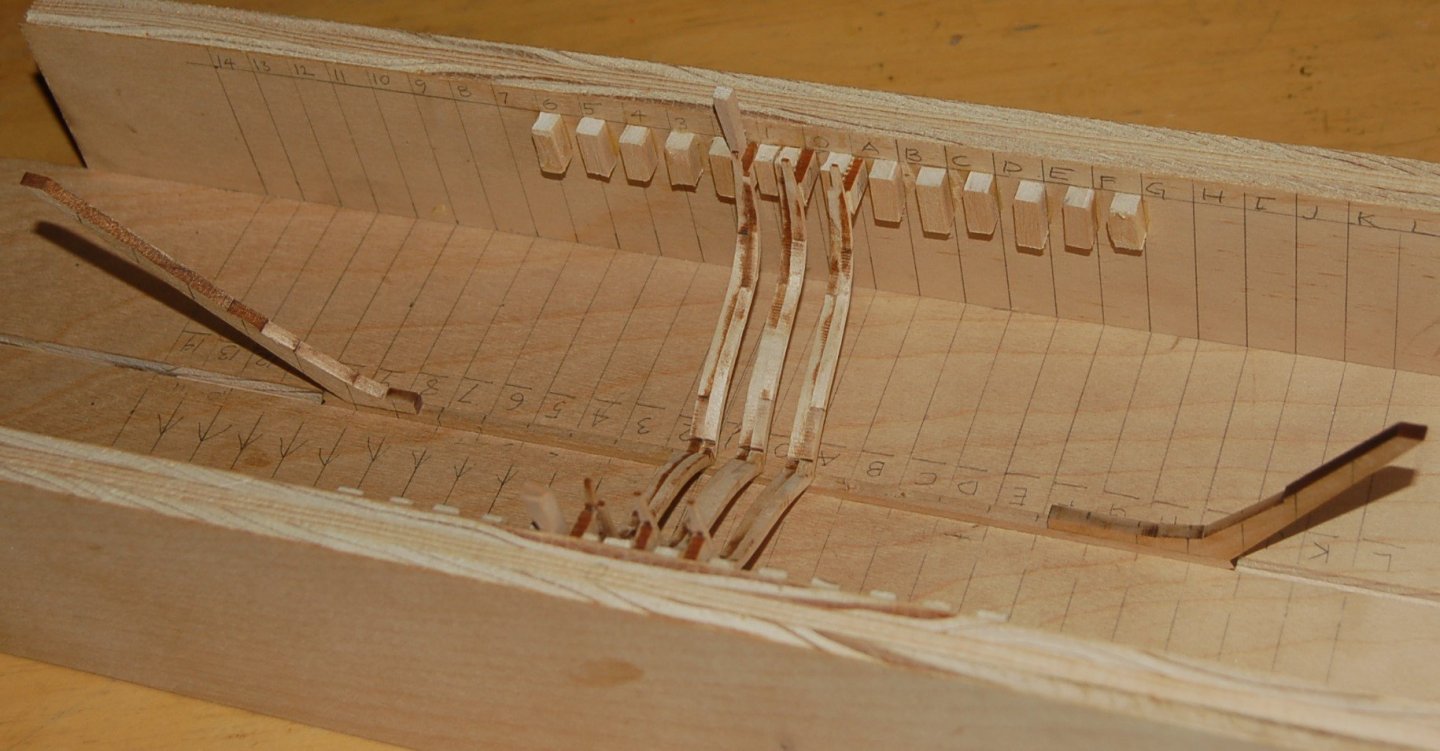
Figure 7‑8 - Two more Ribs Added
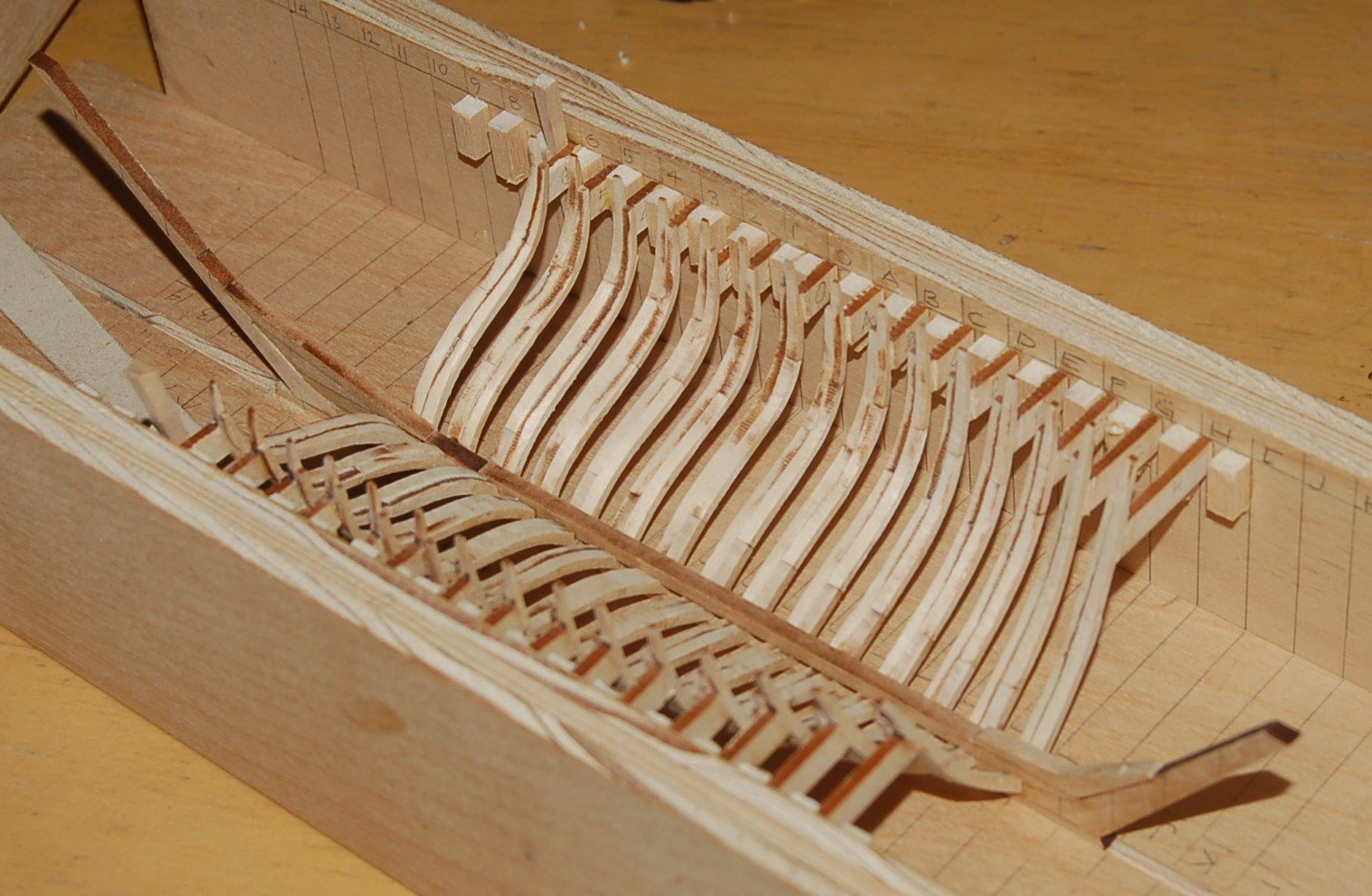
With the bulk of the ribs installed, in this image you can see that the keelson, the stem knee and some of the stern deadwood timbers have been added allowing the remaining ribs to be installed.

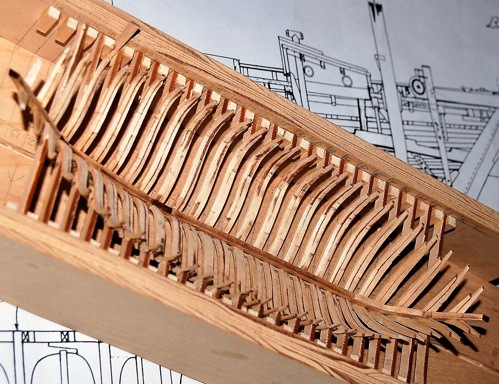
Figure 7‑9 - Most of the Dove's Ribs Installed
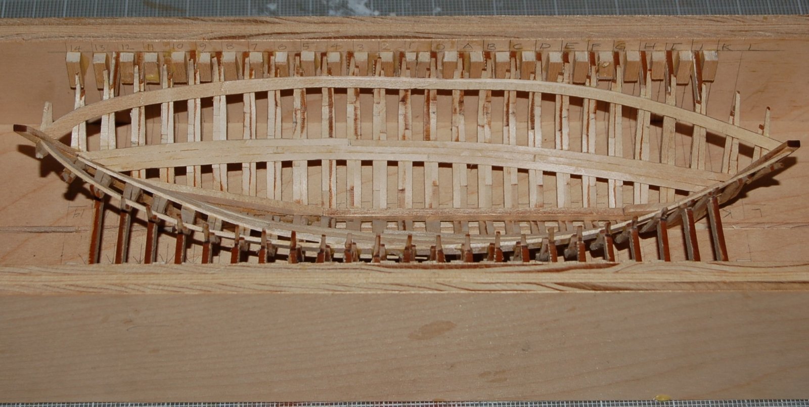
And in the final image of this section, all the ribs are glued in place. The final two pairs of ribs at both the bow and the stern don’t have the erection tabs are simply glued to the stem and stern posts. At last, we have something that looks like a ship.

Figure 7‑10 - Ribs Complete
- GrandpaPhil, Siggi52, Ainars Apalais and 1 other
-
4
-
Burning Wood
Laser Cutter
To my CAD system the laser cutter looks like an old style pen plotter. The cutter takes a series of simple point to point move instructions moving either with the laser turned on or off. It is quite precise and proceeds remarkable quickly.
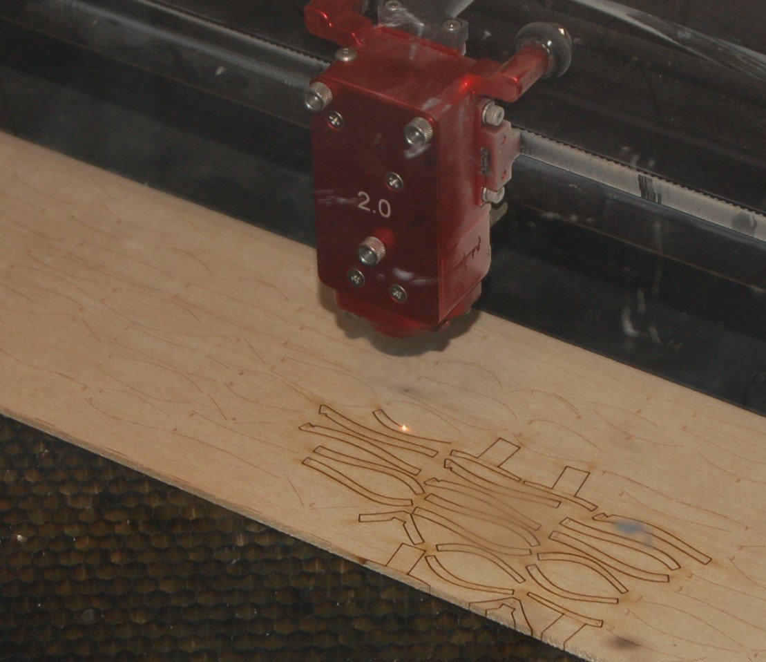
Figure 6‑1 - Cutting the First Pieces
In this image you can see parts being cut. The red device is the actual laser head and directly below it you can see the hot spot where cutting is actually happening. There’s little smoke but can see a buildup of white soot on the head. The sharp eyed among you will also note that I have placed my sheet in the machine too far back and as a result all the pieces along the front edge are being miss cut. Later I would isolate that row of pieces and recut them.
A note on wood. Many modelers use and are proud of exotic wood in their wonderful models. For the purpose of these pinkies, I’ve decided to use simple bass wood. The decision was made for a number of reasons including: the “experimental” nature the project, the generally easy and inexpensive availability of the material, the fact that it has a nice fine parallel grain and because I find bass wood easily workable. For spars I’m using slightly harder birch dowels.
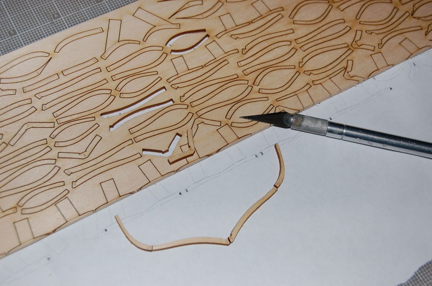
Figure 6‑2 - The First Rib Pieces
In about fifteen minutes I had dozens of little rib pieces to work with.
The bread and butter lifts followed without a problem.
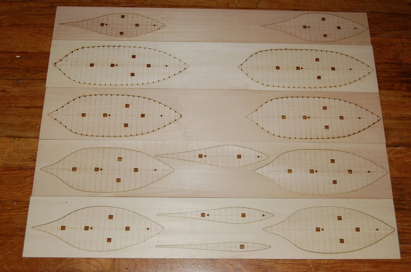
Figure 6‑3 - The Solid Model Lifts are Cut
Next, I begin assembly but as I soon discovered, I wasn’t quite done with the laser cutter. The additional parts needing cutting will be described a bit later on.
- KeithAug, Ryland Craze and GrandpaPhil
-
3
-
Lofting the Solid Hull “Bread-and-Butter” Dove
Water Line Lifts
As I develop this log, I intend to zig zag back and forth between my framed model and my solid hull. So, here are the next steps in making a solid hull model.
I’m assuming that most of you know the concept of building up a solid hull with the bread-and-butter technique but just to make sure, in brief a bread-and-butter model is built up of a number of planks or lifts each cut to the shape of the hull in a series of progressive sections. It can look much like a contour map. In any case, done right it avoids a lot of carving and should be somewhat more resistant to developing cracks over time than could a solid block.
Since I already have a comprehensive set of the Dove’s lines, the easiest approach is to cut my lifts to match her waterlines.
See Figure 3-6 - in a previous post
Additional Water Lines
The Dove’s waterlines were drawn 12” apart and could therefore be modeled fairly neatly with ¼” sheets of wood. Of course, I took a slightly different path. I had a stash of 1/8” stock so I decided to cut my lifts at 6” intervals. This would mean less carving but would mean developing additional waterlines.
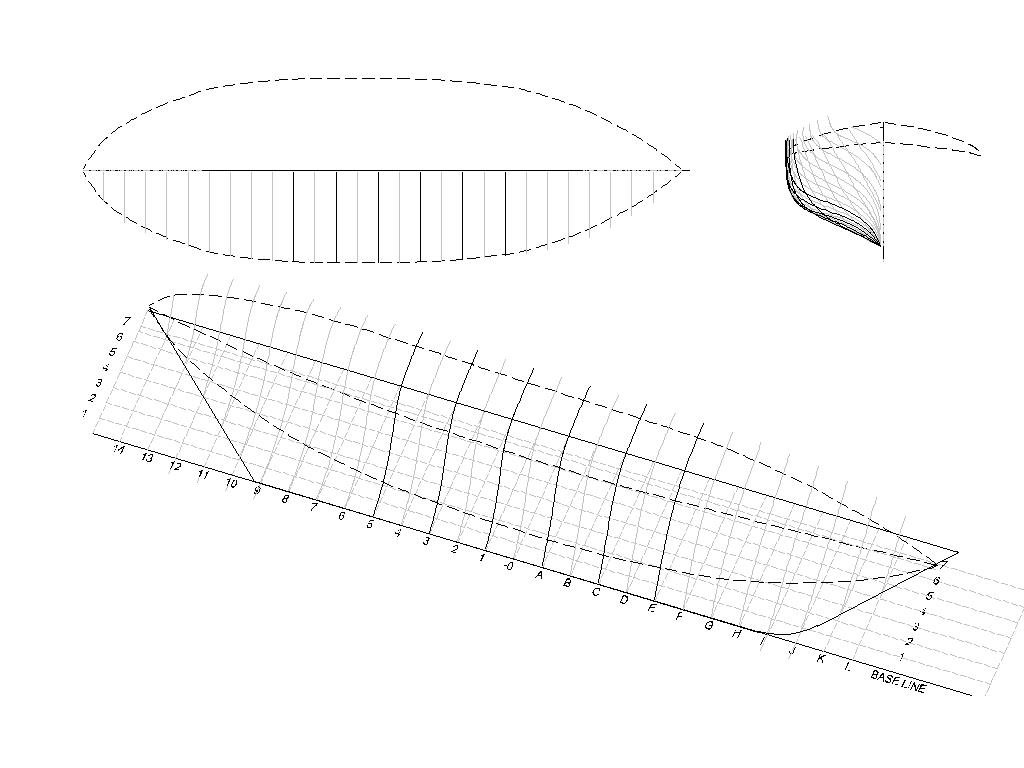
In the drawing below, the solid lines represent the new interpolated water lines.
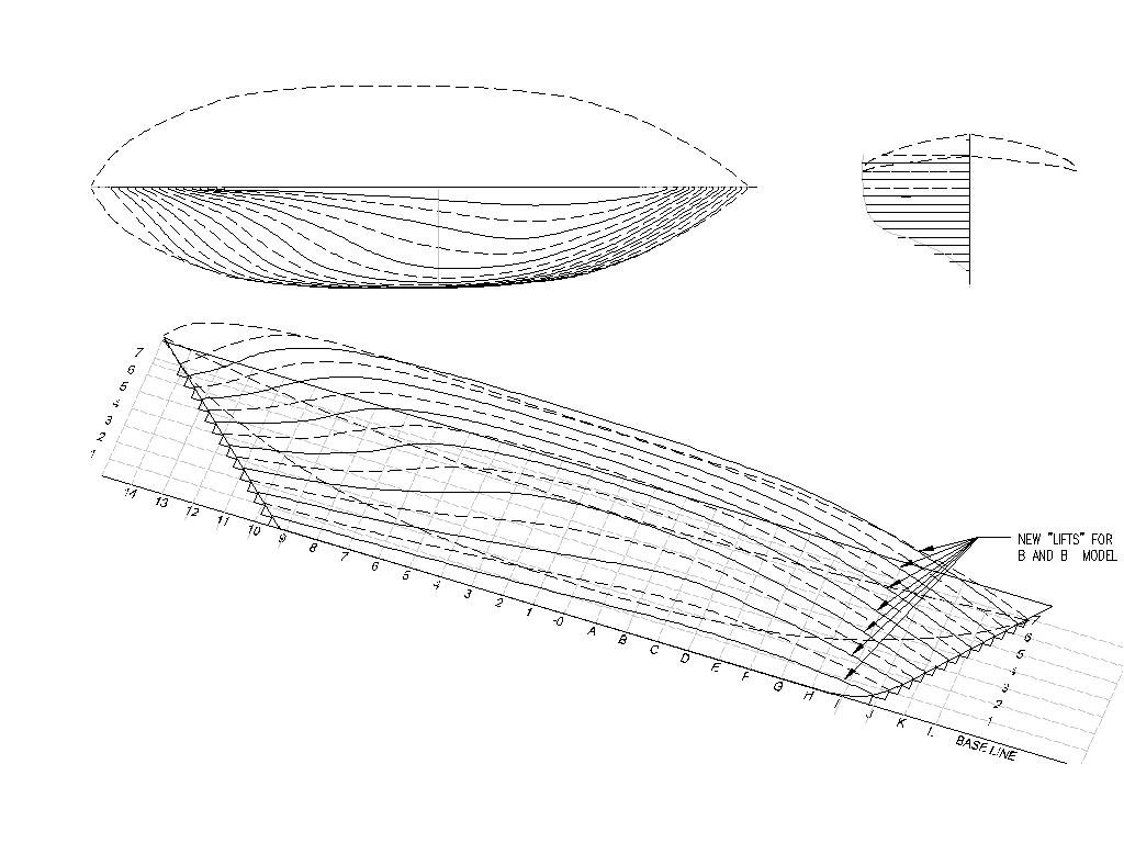
Figure 5‑2 - Additional Lifts Added to the Plan
As the hull tapers out from the keel, it’s important to cut each lift to the largest of the waterlines it touches allowing material to be cut away to achieve the hull form.
Cutting Plan
The Dove has a fairly simple hull form with no Tumble Home so my layout of successive lifts was pretty simple. If tumble home occurred at some point, some portions of the lifts would need to taper in the opposite directions. We’ll cover that trick if I ever get there.
My next step was to extract each half water line from my three D model, mirror it and shift if 4 inches from its opposite side (the width of the keel top) to create a usable lift profile. After that, I again planned on using the laser cutter to make my job a bit easier.
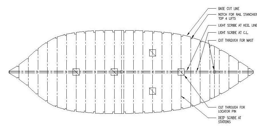
Figure 5‑3 - Planning a Single Lift
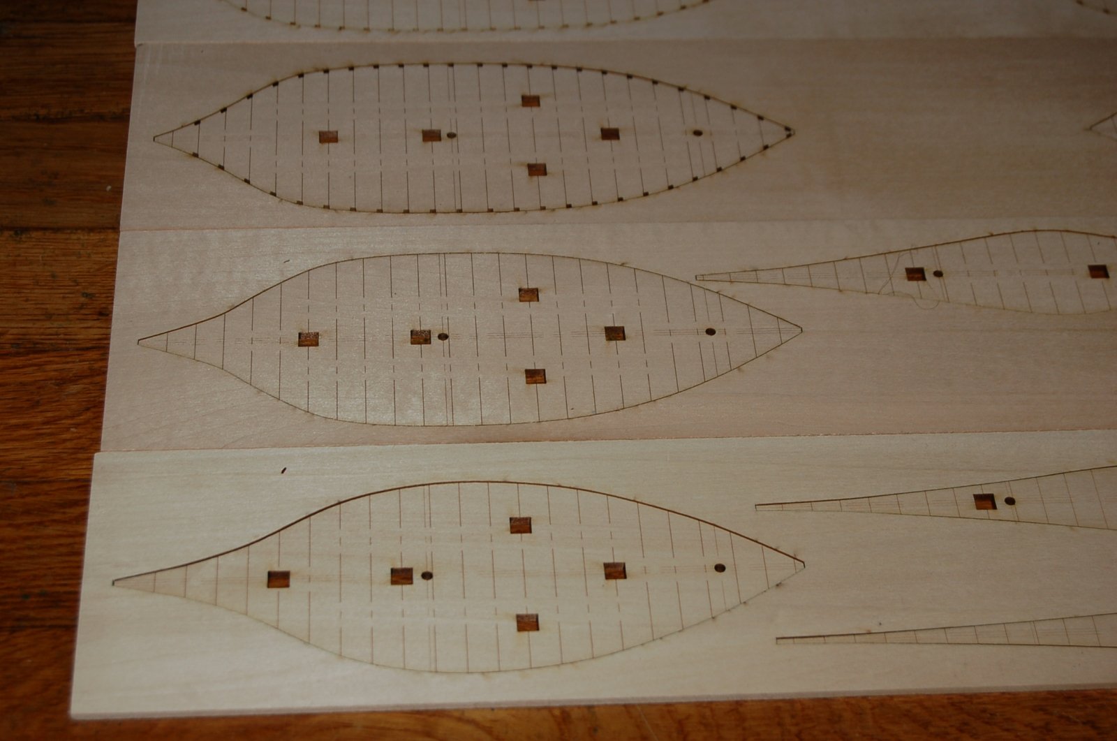
Here, looking a bit like a filleted fish is one of the top lifts. In addition to cutting the shape I will cut out five ¼” square holes which will, with a quarter inch square peg, be used to align the assembled lifts. I will also cut out a pair of 1/8” round holes to guide the location of my masts. Since the masts feature a slight rake these holes will shift slightly forward with each descending lift and will serve as a guide for drilling holes for the masts.
Using a low intensity burn I will lightly scribe the hull centerline and the sides of the keel and posts. I will use a stronger burn (but one that will not cut through) to mark the location of each station on the hull as it’s worked into shape. I also hoped these burned in station lines would reduce any surface stress and minimize warping or cupping before final glue up. Finally, on the upper 4 lifts I created a scale three-inch square notch at the location of each rail stanchion (in retrospect the three-inch fore to aft size was good but I wished I had cut the notches deeper.
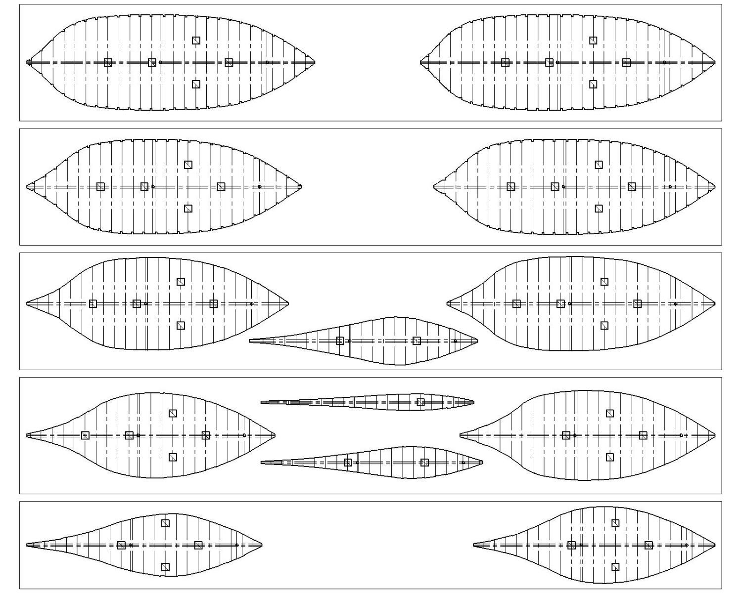
Hoping I hadn’t missed something, or just as likely overthought things, I drafted up thirteen lifts to be cut from five four inch by twenty-four inch sheets of wood. They do look like so many fish.
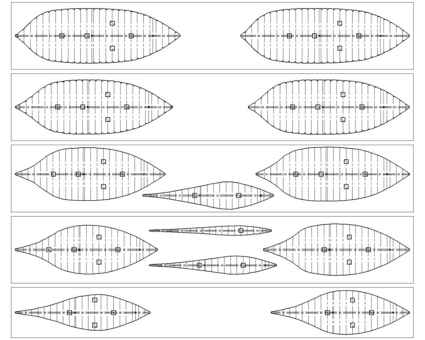
Figure 5‑4 - All the Dove's Lifts
I’m now really ready to burn wood and get on with model building.
- GrandpaPhil and KeithAug
-
2
-
In this post, which I'm titling "Lofting the Framed Dove" I get a bit closer to thinking about building an actual model.
First there's filling the Gaps
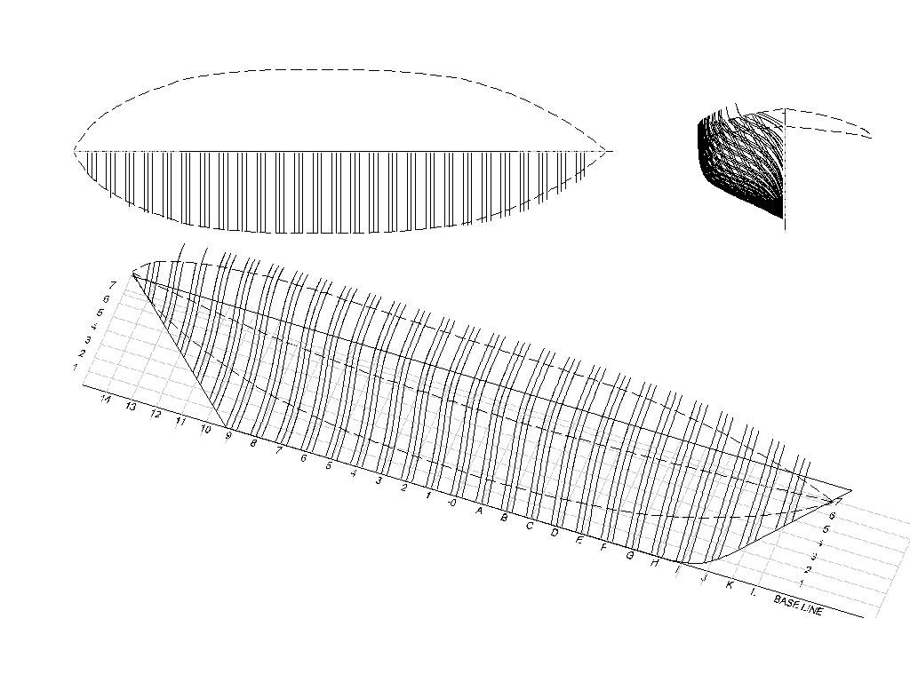
Now that I have a nearly complete set of lines, I need only to add the lines left out of the original plan (at stations A, C, E, 1, 3, 5) but that I need to loft a full set of ribs. These lines are interpolated between the given half breadth lines by projecting new offsets that touch the waterlines, buttock lines and diagonals. This adds the following six new lines.
Figure 4‑1 - Infill Half Breadth Lines
The result is 27 half breadth lines each of which is the center line of a rib.
Ribs
Each rib will be laminated from what will initially be 1/8” stock. I could cut the ribs based on the center line but in many cases that would leave portions of the cut face of the rib undersized. To properly size each rib at some point I would need to know it’s smallest profile, its largest profile and the shape at the center where both halves meet. in order to calculate the shape of all the rib faces, my next task was to create two more lines one six inches in front of the center line and one six inches in back. These lines represent the nominal forward and after face of each rib (the ribs will later be shaved down to match the fore/aft taper specified in the plans).
Figure 4‑2 - Thickness for All Ribs
The new lines were of course developed using the same process as used to interpolate the missing ribs creating new lines six inches off the rib center line. A bit tedious but nothing new. My 27 half breadth lines had now become 81 rib face lines. One at a time I copied each line from the hull model and addressed it as a flat (2D) line in my CAD system.
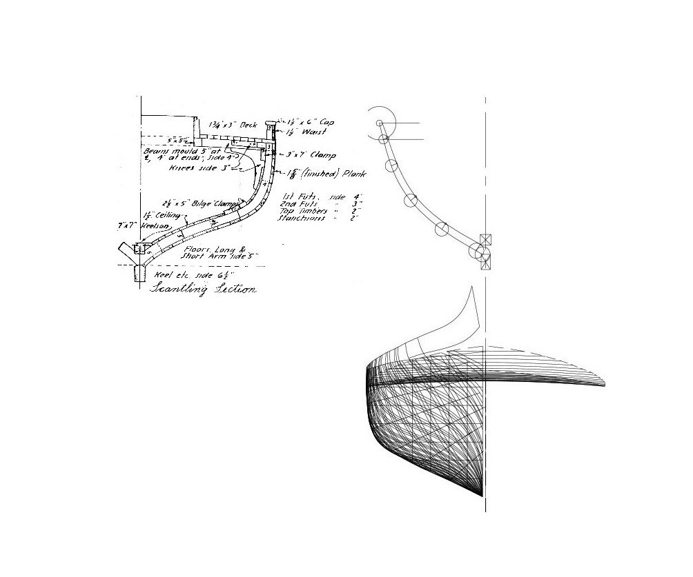
Referring to Chapelle’s Scantlings Section, I found that each rib was molded 5 inches deep at the keel and tapered to 3 inches at the underside of the deck then to two inches at the underside of the rail. Using a series of circles spaced along the rib I established the taper with a new spline giving me the inside shape of the rib at each face.
Figure 4‑3 - Extracting a Single Rib
Since I would be shaving or “dubbing” the ribs to fair the hull before planking (both inside and out) each rib needed to be large enough to be shaped without cutting it below its design dimensions. As a result, the ribs were initially cut to the maximum profile of both the outside face and the centerline. Also, in addition to simply doubling up the ribs fore and aft, each would be cut into overlapping futtocks (shorter sub-sections). This again approximated original design but also would enable me to cut most of the rib segments with their long axis close to the wood grain preserving as much strength as possible in what would be fairly delicate ribs. Finally, at the time I was doing this work I had access to a laser cutter which I would use to do the cutting so I needed to think about the cutting tool path in laying out my parts.
 Figure 4‑4 - Developing a Single Rib
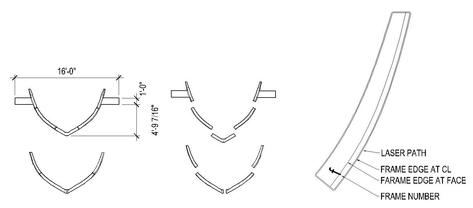
The image above to the right shows a single futtock. I included the shape of the rib and offset a parallel line a short distance away to establish the path the laser would take hoping to allow room for the laser to burn away enough wood to cut my part but not so much as to reduce the size of the piece. Generally, I was successful but perhaps didn’t adequately take into account the fact that as the laser burns through the wood it produces a “V” shaped cut, wider at the top and narrower at the bottom as the cut was completed.
Lasers can also be set to lower power settings allowing me to “burn” additional information into the piece without cutting through. I burned the rib number into each piece in this case “f” and a line indicating the true front edge of the rib at its face, giving me a target to fair to.
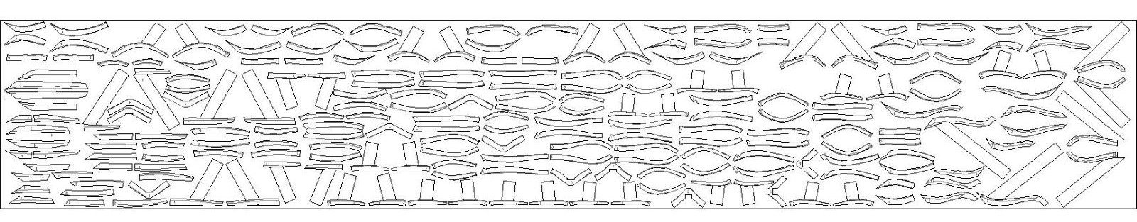
To the left I’ve included drawings of a single rib pair: one of four segments running from keel to underside of the deck and the other five segments with a “V” shaped piece sitting on the keel and reaching to the underside of the rail as the stanchion. I’ve also added two tabs to the upper pieces of the rib. I’ll call them erection tabs and they will be used to stabilize the rib while I build up my hull. The ribs were then broken up into smaller CAD drawings, each representing a single futtock. The process was repeated for all the Dove’s ribs. Finally, all the designed rib plans were laid out onto a single 4” x 24” rectangle with each rotated to have its long axis as near as possible to parallel with the grain of the wood.
 Figure 4‑5 - The Cutting Plan for All the Dove's Ribs
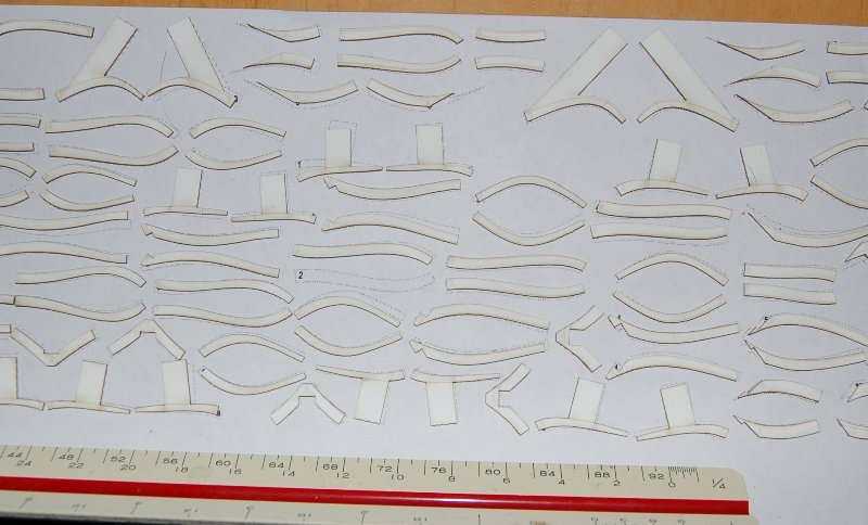
I was now one step away from cutting wood. First, I would cut a piece of chipboard to test my work. Here are some of the test pieces:
Figure 4‑6 - Test Ribs Successfully Cut
They’re a lot of them and the pieces are small but the process seems to work. As soon as I figure out how to approach the bread-and-butter solid hull, cutting wood will follow quickly.
- GrandpaPhil, Mirabell61, mtaylor and 1 other
-
4
-
What a wonderful project!
I think if it were up to me (which it isn't) I'd stick as close to your father's initial approach rather than doing too much to update the model. The connection to your father's handwork could be quite valuable.
I'm sure there are many good sources on the Cutty Sark, especially in England, however if you can find a copy of Nepean Longridge's The "Cutty Sark" that isn't too expensive you might enjoy it and get some useful direction in modeling the Sark. My dog eared copy was published here in the US in 59.
Jim
- Keith Black and mtaylor
-
2
-
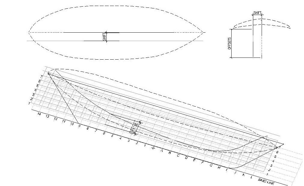
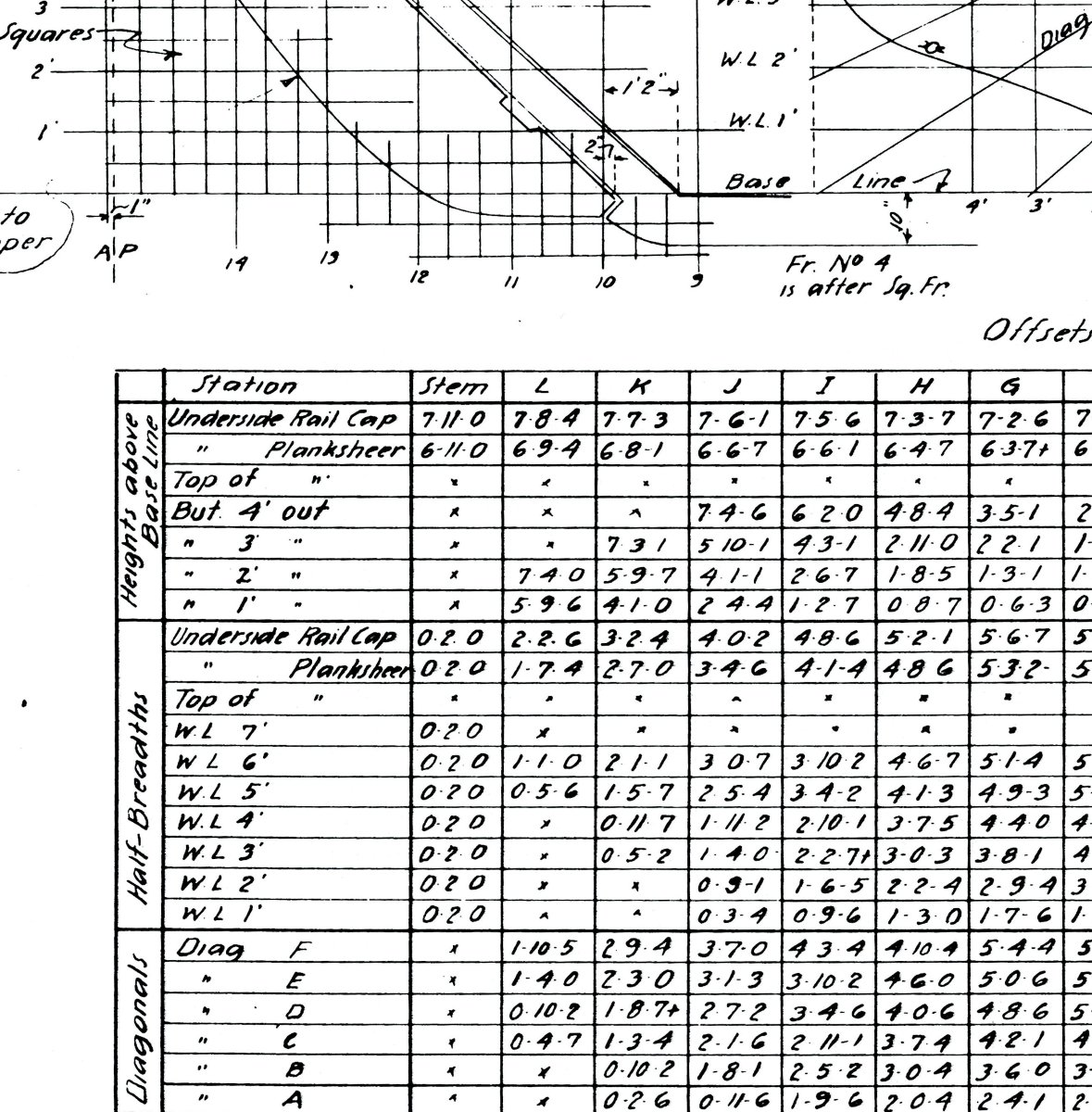
...so a bit more on extracting the shape of my hull from table of offsets Chapelle included in his set of drawings. I'm not sure if they come from the builder or from Chapelle's measurements of the builder's half model.
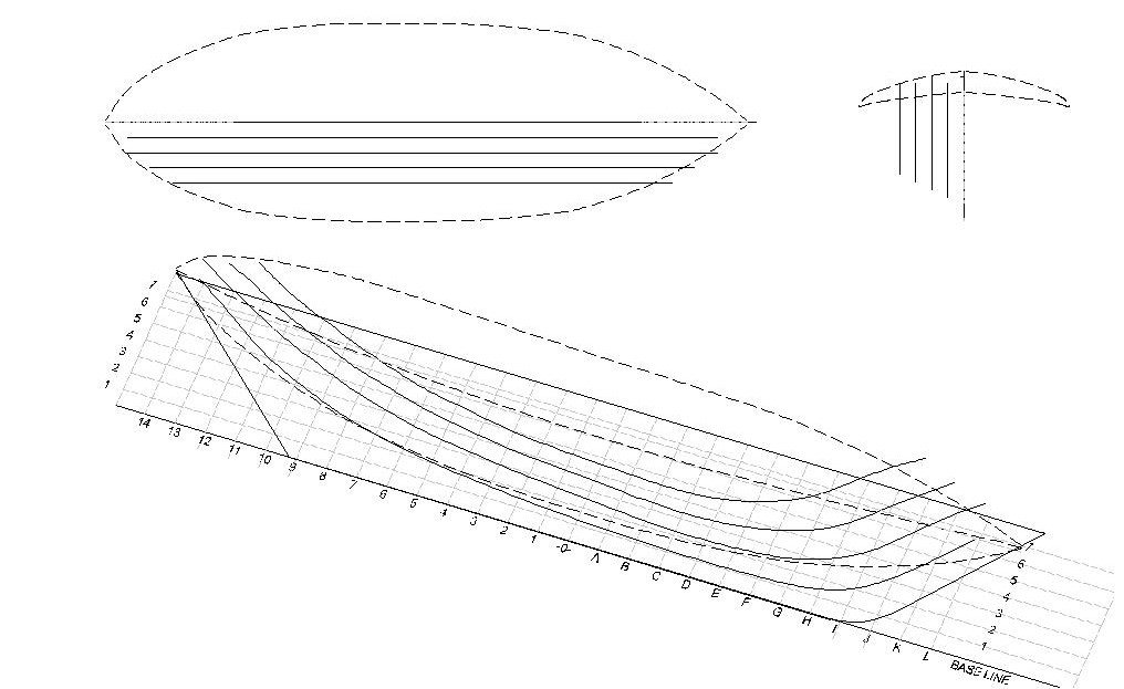
Buttock Lines
The next lines I constructed were the Buttock lines. These lines are offset vertically from the base line but each of the four buttock lines is also shifted away from the from the keel center at one-foot intervals.
The following example shows the second Buttock, shifted 24”s from the keel then then offset vertically (from the keel / base line upward toward the deck.)
Adding all four Buttock lines yield the following form:
Diagonal Lines
The final group of lines used to define the hull shape are the diagonals. For the Dove we are given offsets for six diagonals that are projected around the hull at varying angels and look a bit like planking. Each is offset from the Dove’s centerline projecting outward along a sloping plane. The plane being defined by its vertical intersection with the centerline plane and its horizontal or vertical intersection with the rectangular faces of a box whose bottom is the base line and the left side is at the extreme beam.
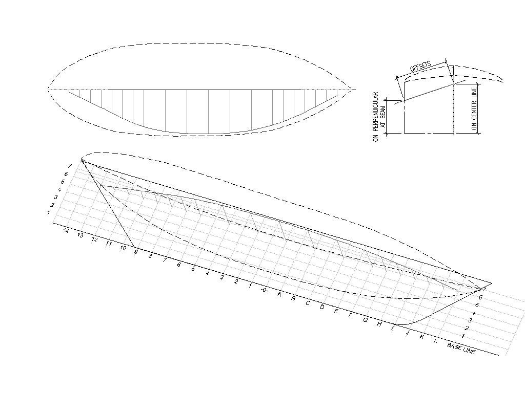
The six diagonals give us the following:
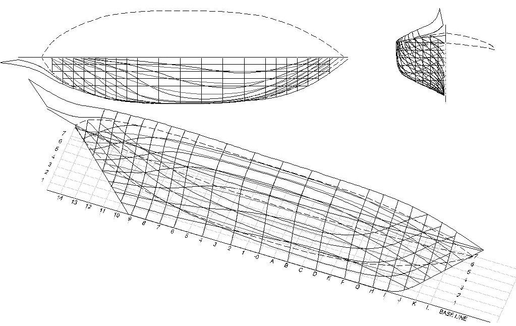
Referenced together, all these lines give us a fairly complete (if not a bit confusing to look at) image of the Dove’s hull.
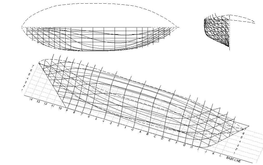 gure 3‑11 - All Lines Together, The Full Set
The table of offsets also includes data locating the plank shear line which I have shown dashed in each of my examples and the line at the underside of the rail cap which will be useful when figuring out the Dove’s pinked stern. It looks like this:
With the two-inch offset at the keel or stem and stern posts we give the builder 1 ¼” thickness to fair the planking into a 6 ½” keel.
With these lines entered into my computer the next task was to check them for fairness. This took two forms of activity.
First, I made sure that all the lines intersected where ever they crossed. Because of the way they are constructed the half breadth lines and the waterlines are guaranteed to intersect as they both use the same offsets to develop lines either vertically or horizontally. The buttock and diagonal lines are trickier and need to be closely examined.
Chapelle gives a bit of guidance in sorting out issues writing on the table:
“Note to loftsman. Buttocks to control in afterbody, waterlines in forebody when offsets do not fair.”
I quickly learned that in those incidents where a gap was discovered the spline control point being adjusted needed to be moved along its original offset line until it touched the line to which I was bringing it. Doing anything else quickly turns the model into a hash.
My second activity consisted of examining the model for bumps and wrinkles. I found several most of which were trivial to fix and one that clearly represented an error in creating the offset table as it stuck out like a sore thumb. In each case where correction was needed the spline control points were slid along their offset lines, preserving the intersecting mesh, until each line ran fair.
The following illustration shows, with exaggerated curves, the types of errors I looked for and indicates that where errors occur, they tend to ripple across several station points. In this case, the mathematical spline curve generated by CAD systems mimic the behavior of wood battens or even planks in that once pushed off fair in a single location, problems can occur in adjacent spans.
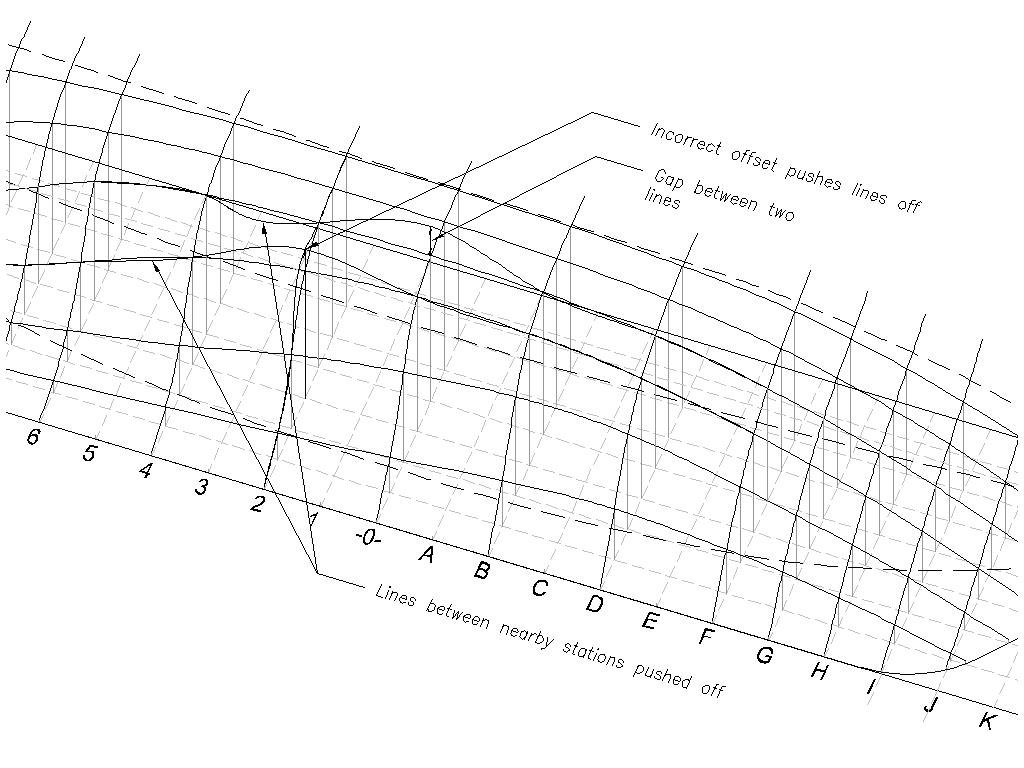 Figure 3‑13 - Looking for Problems
Using my CAD system, I found that the ability to dynamically rotate the model on my computer screen was a huge help. The often-incomprehensible mesh of lines quickly snaps into a visually sensible surface as the model is rotated. I found that tracking each line by eye fore to aft or top to bottom as the model rotated quickly revealed problems. As it turned out, most of the problems I found with the Dove were with the smooth run at the top of the rail.
In the end, I’m not sure if all this effort with the table of offsets actually saved me any time or made the model all that much more accurate but in completing this exercise, I certainly came to better understand the development and purpose of the ships lines and to appreciate the role of the naval architect. I do believe that as a result of the checking and corrections
I made in this process the models I built presented fewer issues with fairing and planking when converted to wood.
That process will be covered in the next posts.
- GrandpaPhil, Jond, Mirabell61 and 4 others
-
7
-
Perhaps the first eccentric step in my process was the decision to use the Table of Offsets to shape my model, discarding at least temporarily the three other sheets of plans in the set.
The table purports to be numeric or digital representation of the hull form (coming from a very non-digital time). Being numeric it is scale independent but can be used by the loftsman to directly layout out each of the ships lines without needing to make scaled measurements from the plans.
The next two posts describe how I used the table. (Those of you who already understand the process or find it tedious may want to skip ahead to future posts where wood is actually cut.)
Using the table presupposes an imaginary grid stretching the length of the Dove’s hull. The base line of the grid is a line at the center of the top of the keel. The horizontal lines of the grid are parallel to the keel and spaced vertically at 12 inches intervals numbered 1 through 7 from the bottom up. The vertical lines of the grid, called stations, are spaced 18 inches apart and are numbered outward from the widest portion of the vessel or station -0-. Stations forward of -0- are actually lettered A-L. Stations aft of -0- are numbered 1-14.
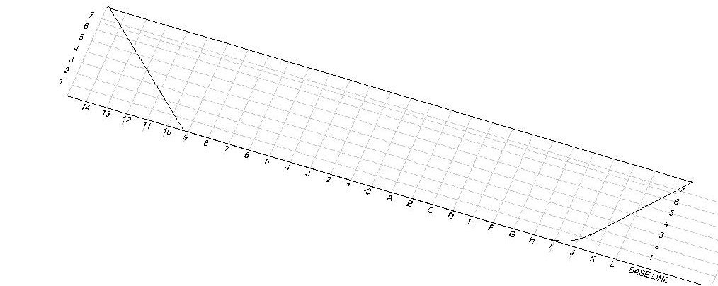
Figure 3‑2 Basic Layout Grid for the Dove
The first lines I extracted from the table were the half breadth lines. These lines define vertical sections through the hull and are often, as in the Doves case, equivalent to the center line of the ribs. As an example, to extract the half breadth line for station -0- you read from the half breadth section of the table along the vertical line labeled -0-. At WL1,-0- we find the offset 1 6 4. Read in feet and inches this is 1’-6 ½” (The final 4 representing 4/8s inch). Proceeding upwards we find the offsets: 3’-11”, 5’-10 ¼”, 6’-3 7/8”,6’-5 ½”, 6’-6” and at the plank shear 6’-6” and at the rail cap 6’-5 7/8”. At the base line and the stem and stern posts, the vertical offset will always be 2”s allowing for the measure from the centerline to the back of the planking bevel.
Half Breadth Lines
In my CAD software (AutoCAD), I constructed the grid then at each intersection along station -0- I added a vertical (Z direction) line matching the offset lengths from the table. Finally, I used the CAD system’s spline tool to connect each offset line. My first half breadth line.
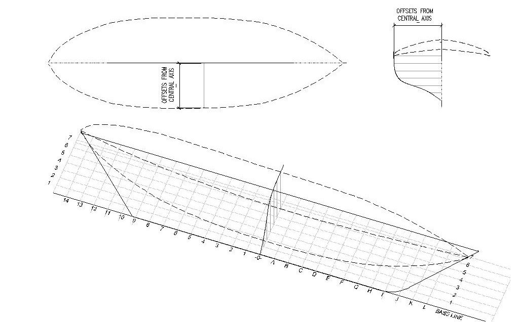
Figure 3‑3 - Offsetting a Half Breadth Line
 Adding offsets and splines at each station results in our first 3D look at the hull form.
Figure 3‑4 - A Full Set of Half Breadth Lines
In the Dove’s case stations A, C, E, 1, 3, and 5 are omitted from the table, I believe because they produce half breadth lines perceived as being too similar to the adjacent lines. Since it is my intention to create a rib for each station line, I will need to interpolate lines for the missing stations.
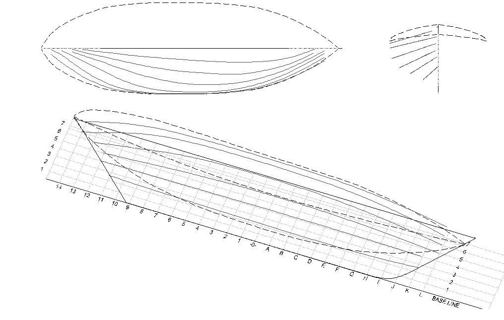
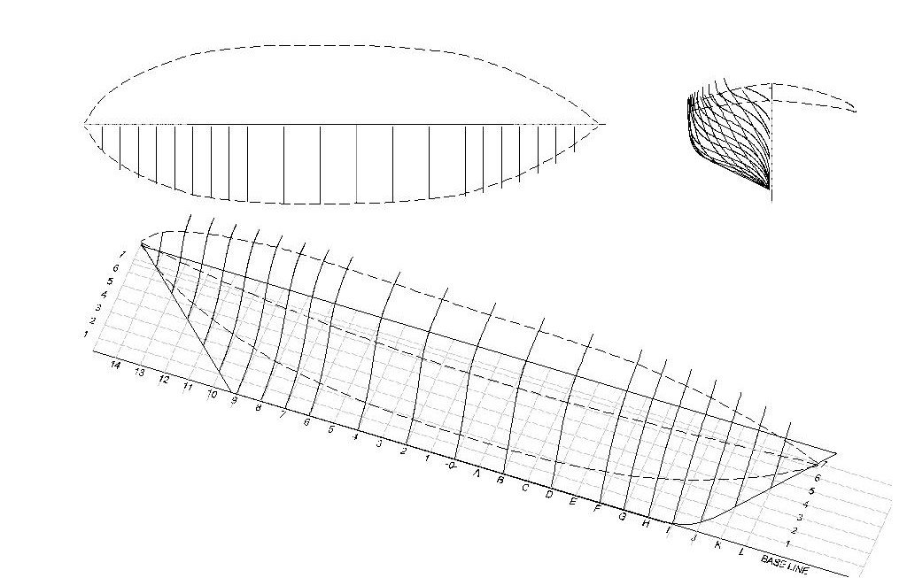
Water Lines
The next lines to be extracted from the table are the “water lines”. These are sections constructed parallel to the top of the keel. However, as the keel of the Dove has significant rake, the water lines are not in fact parallel to the Dove’s actual water line. Here the process is quite similar to the construction of the half breadth lines and in fact uses the same portion of the offset table this time reading the offsets from the table horizontally rather than vertically. Below are the offsets and spline for water line 4.
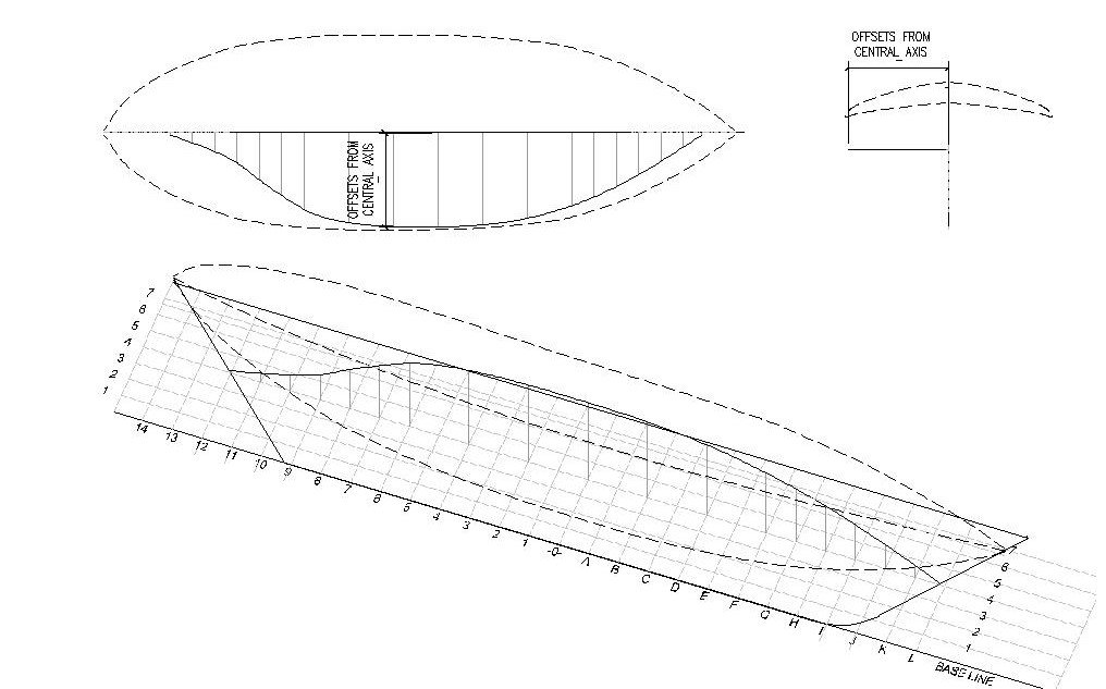
Figure 3‑5 - Offsets to Construct a Water Line
The Dove’s seven water lines give us this form:
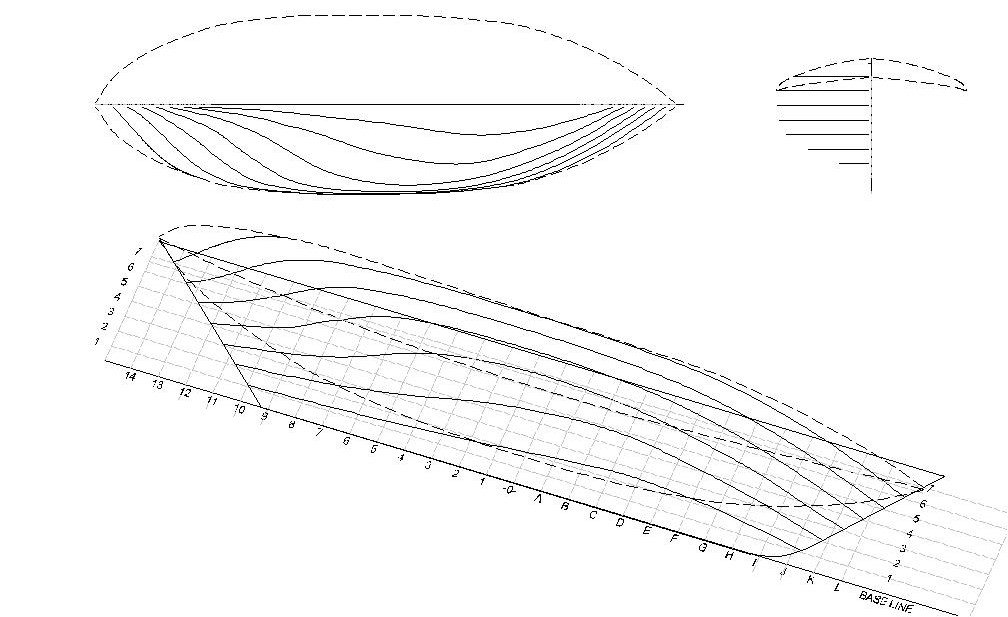
Figure 3‑6 - A Full Set of Water Lines
My next post will cover buttock lines, diagonals and my fairing process.
-
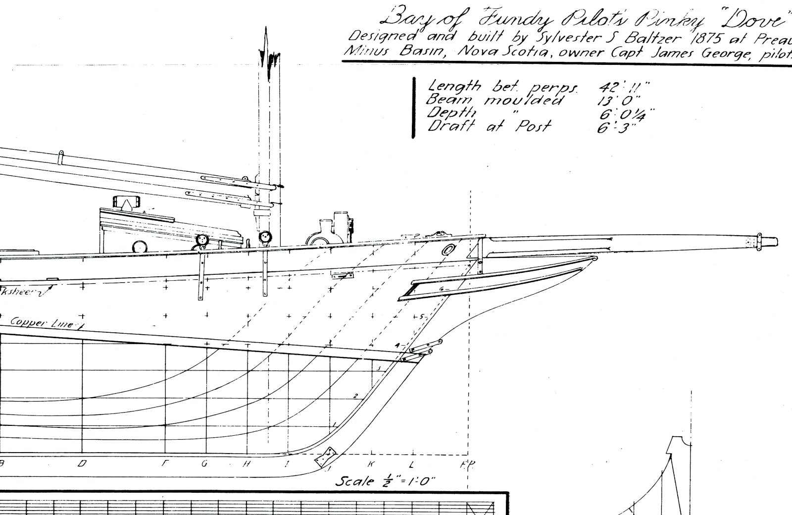
The Smithsonian plans were all drawn by Howard Chapelle, who had traced the builder’s plans and half model which was then in the hands of the builder’s son.
In The American Fishing Schooner Chapelle reports that the Dove, a pinky schooner, was designed and built by Sylvester S. Baltzer in 1875 at Preaux Minus Basin Nova Scotia for Captain James George a pilot operating in the Bay of Fundy. She was 42’-11” between perpendiculars, 13’-0” beam molded, the depth was 6’-0 ¼” and she drew 6’-3” at the post. The Dove was noted for her sailing qualities and for being unusually yacht like. I wonder if the provenance may be important in ways that could affect the accuracy of my model. Per Chapelle’s report, the builder’s son who had held onto the plans was himself an accomplished boat builder. He retained the half model and construction plans because he intended to build a copy for himself. While the Dove was a late design of the type I believe it’s possible the son may have updated the plans even more with modern schooner fittings as he thought about building it another time.
Chapelle tells us that while intended as a pilot’s vessel, she had the general arrangement and rig of a fisherman. I’m assuming that her use as a pilot allows me to show a finer finish that typical for a fisherman. For example, noting the inscription “Copper Line” on the plans, I decided to use copper plate rather than the typical red anti-fouling paint.
The plans come as four large sheets each featuring half inch to the foot scale drawings all executed in Chapelle’s typical clean descriptive style. The sheets I received were black line copies made from originals that showed some wear presumably from repeated examination and copying. Also probably resulting from the copying process, two of the sheets had minor scale issues.
As the site hosts have noted at the bottom of this post my original images were in violation of a copyright and appropriately removed. It was also pointed out that if I post an extract from the image it would be acceptable under "Fair Use" rules. This is what I now do. (if you wish to see the full images you can refer to Chapelle's The American Fishing Schooners where they are included).
Hull Plan
The plans included a hull plan featuring all the lines you would expect along with dimensional information. The lines of the rail and bow treatment are indicated and a scantling Section with helpful framing dimensions is included.
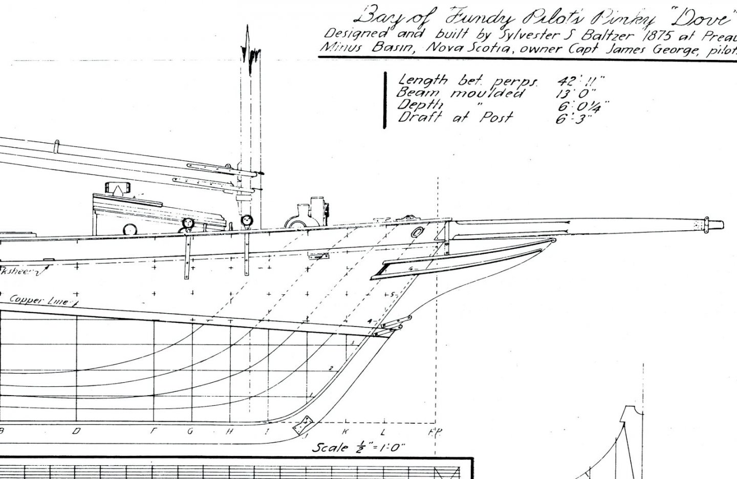
Figure 2‑1 - Dove Lines
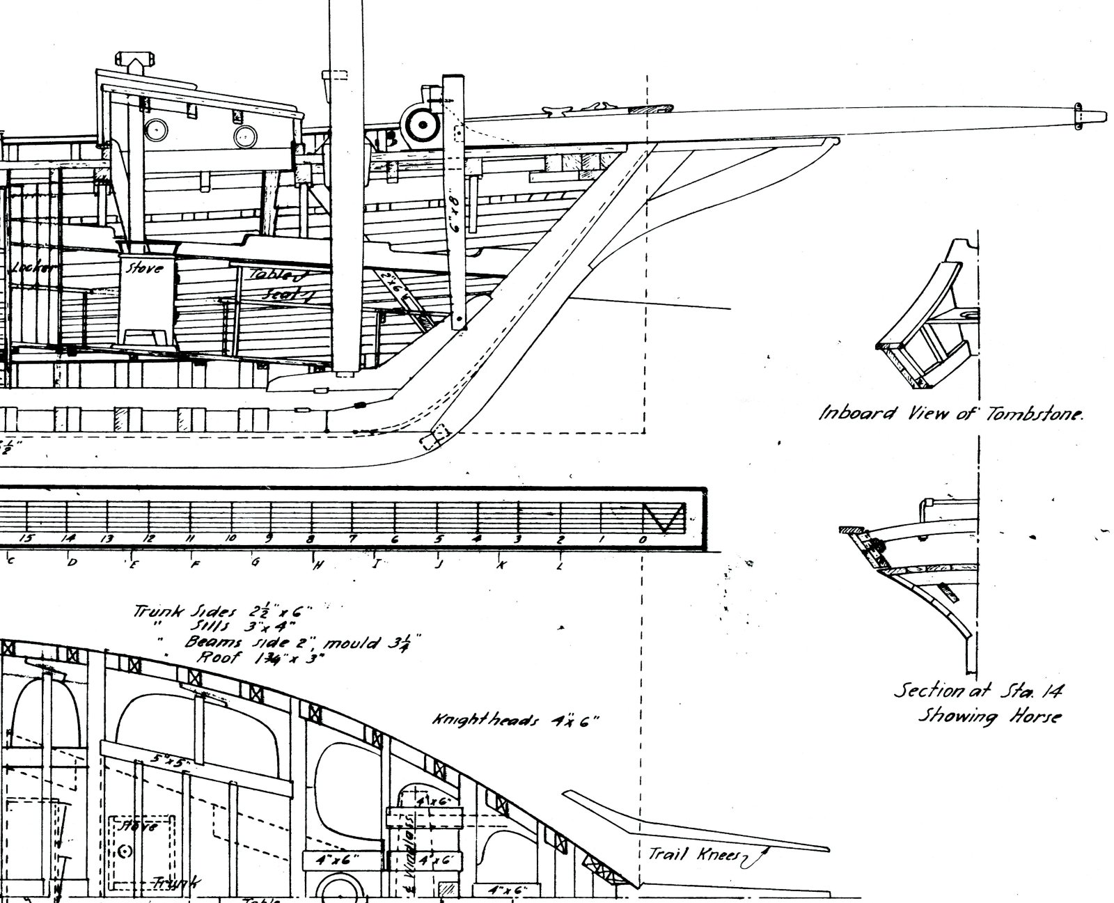
Framing Plan
A framing plan with considerable detail about the frame layout and member sizes, Cabin and other below deck features are included and two small sections describe the construction of the Dove’s pinked stern rail.
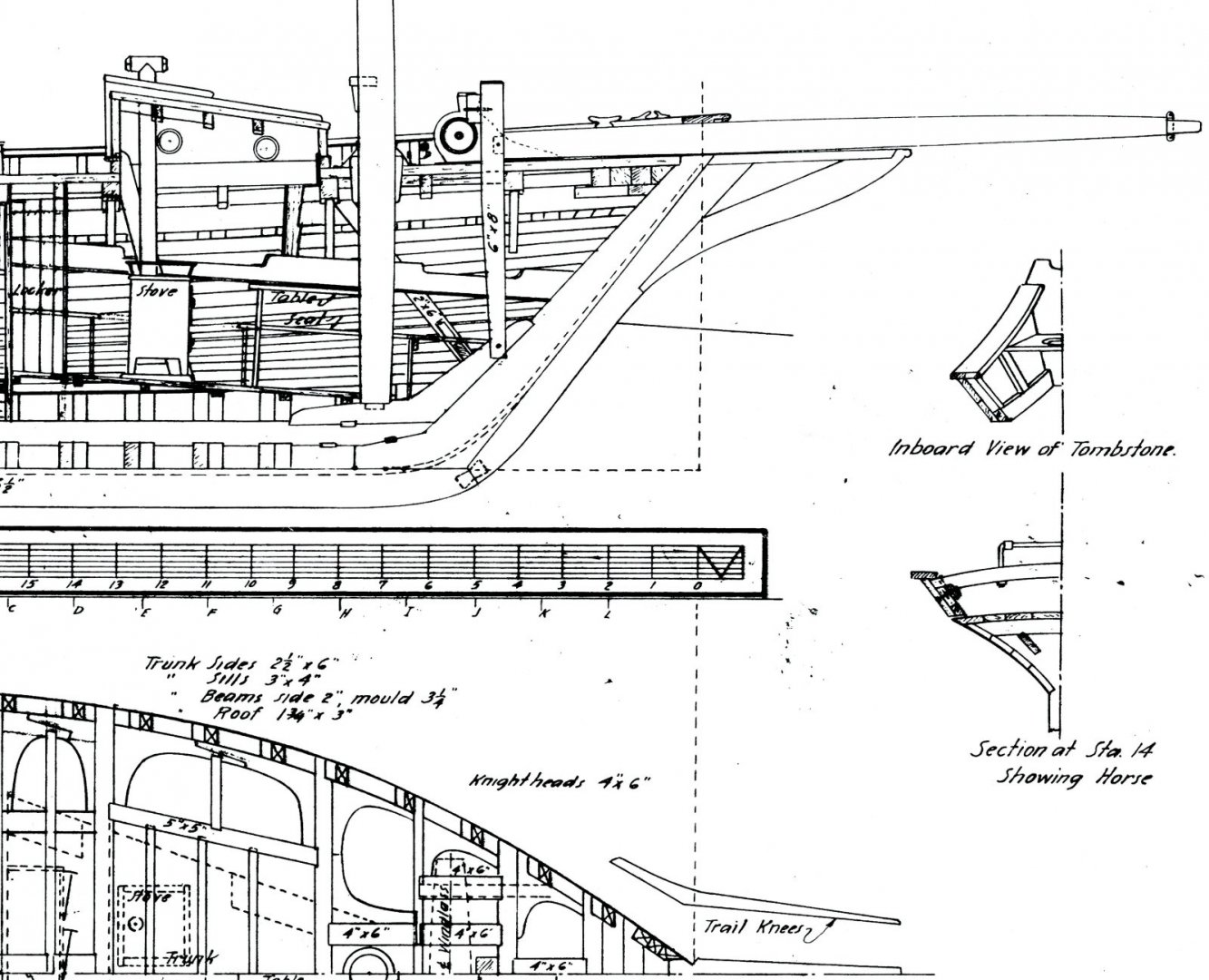
Figure 2‑2 - Dove Framing Plan
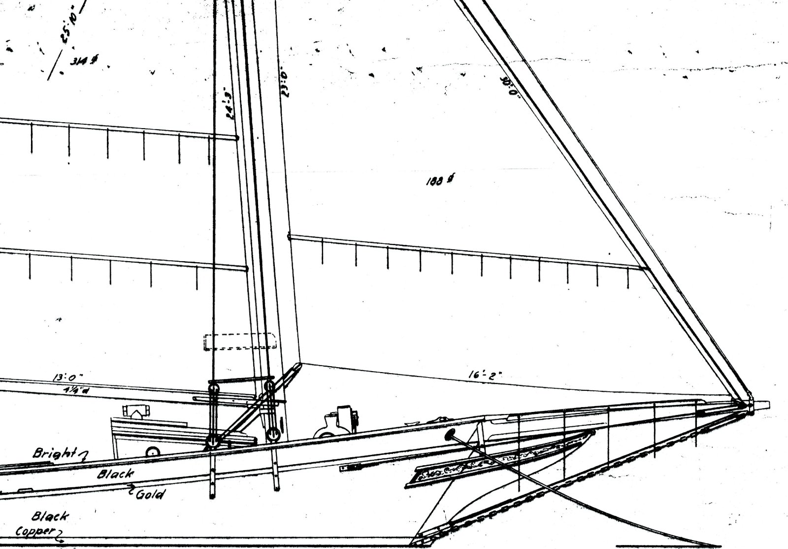
Sail Plan
A larger sheet with a sail plan (still at 1:24 scale), a table indicating spar dimensions and limited indication of the rigging arrangement. The Dove appears to have many of the rigging features of later fishing schooners. There are also color and finish hints as well as an indication of bow decoration.
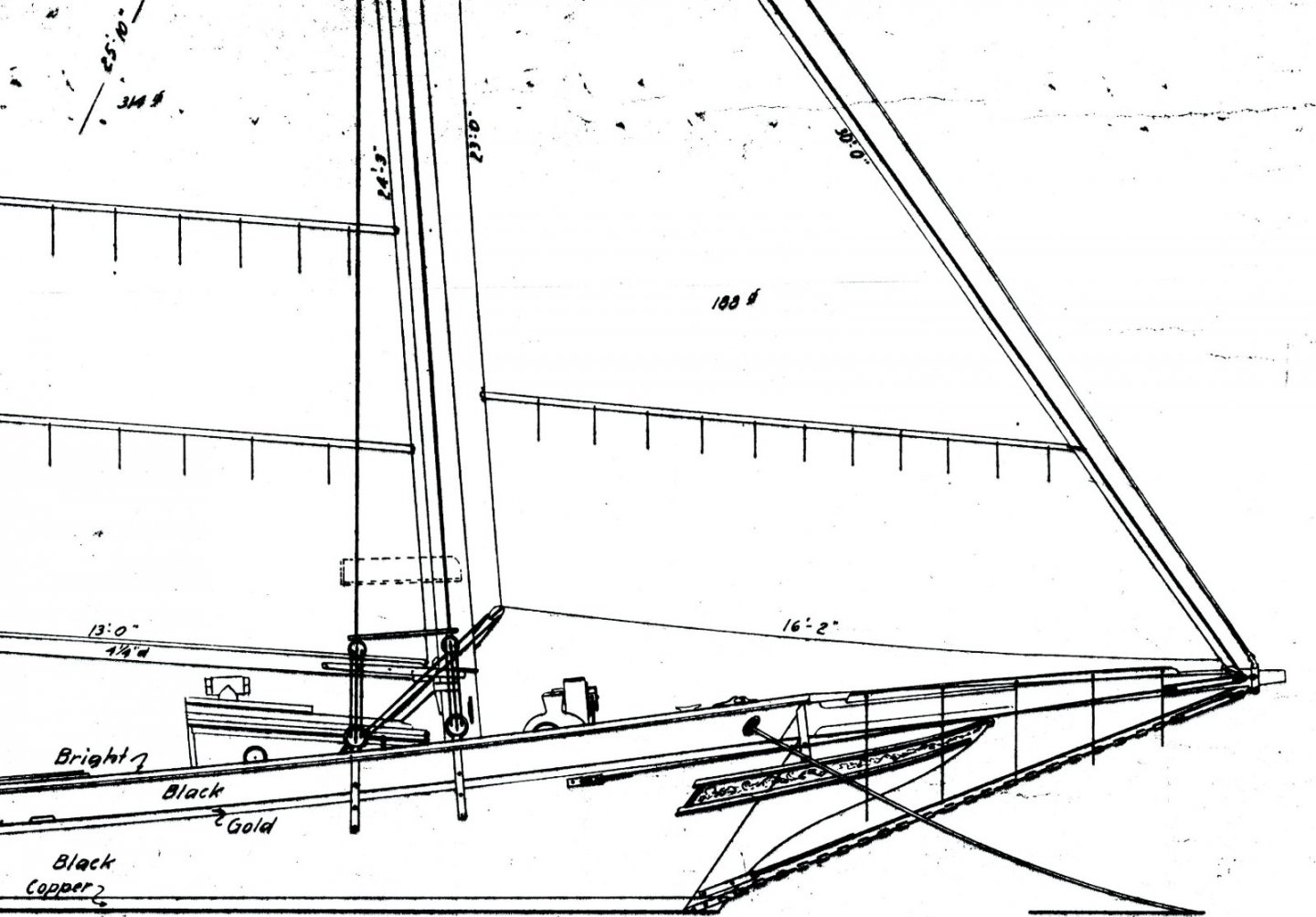
Figure 2‑3 - Dove Sail Plan
Table of Offsets
And finally, a sheet featuring the profiles of the bow and stern and most interesting a complete table of offsets. A legend on this sheet indicates that the offsets were taken off “the half model”.
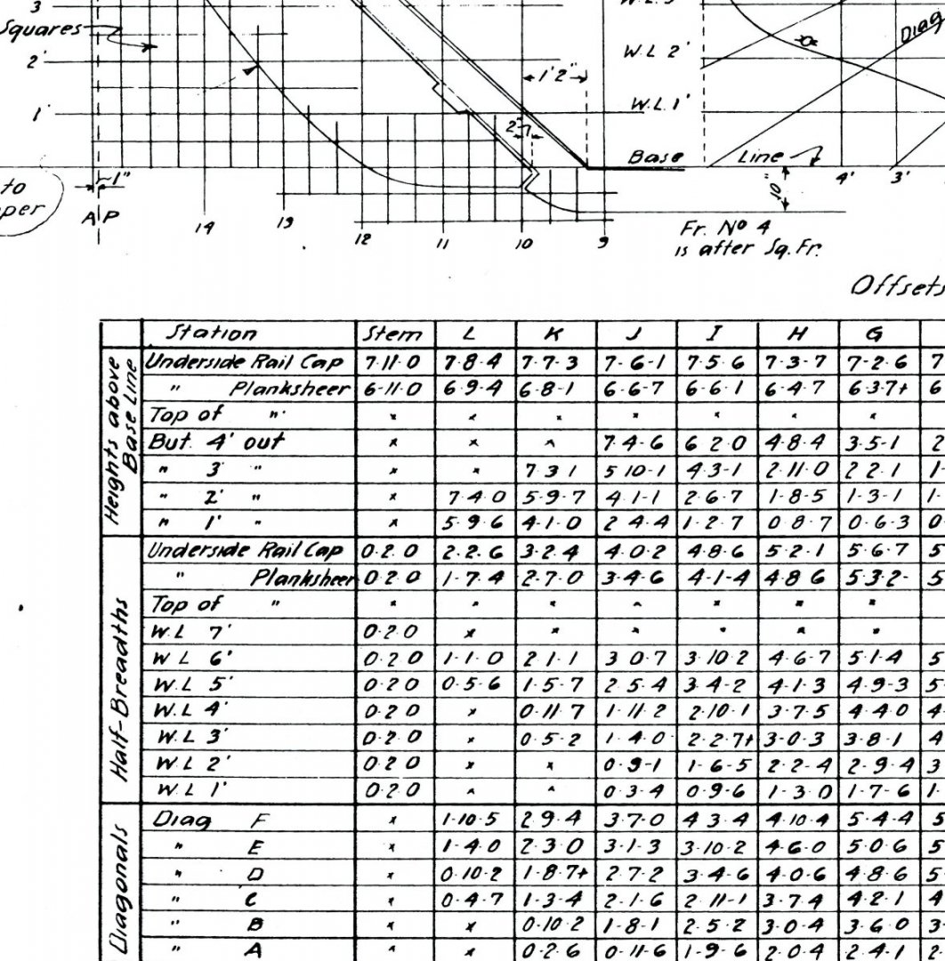
Figure 2‑4 - Dove Table of Offsets
Nice as they are, these plans are not complete. Missing information includes: complete rigging details, a deck plan and a plan showing the rigging line terminations at the miscellaneous pins and cleats. There is also very little on deck furnishings and detailing of the masts and rigging. I believed I would be able to approximate the missing information using Chapelle’s The American Fishing Schooners where the Dove’s plans had originally been published.
As I studied the freshly delivered plans, I started to plan my adventure. Several early decisions would do a lot to shape the following years of effort. They included:
· While the plans were 1:24 scale, I would make my model 1:48 scale matching the Latham’s scale and allowing comparison between the models.
· Since I had easy access to fairly powerful CAD (AutoCAD) I would use that software and the Table of Offsets to develop my model rather than tracing and scaling the lines off the drawings.
· Since this would be an exploration of scratch-built modeling techniques, I would explore more than one technique. Initially I thought I would look at “plank on bulkhead,” “Plank on frame” and solid hull “bread and butter” modeling techniques.
· As near as possible, the models would be 100% scratch work.
Eventually a measure of sanity wedged its way into my thinking. I had already built two plank-on-bulkhead models and wasn’t all that crazy about the method. I decided I’d do the Dove twice, two models in parallel, one model using the plank on frame method, and the other bread and butter methods to create a solid hull.
So, I had a plan and it was time to begin, I was on my way. I had no idea of how long it would take me to get anywhere close to finished. I’m still on the way.
Jim
EDIT: Jim, those plans have been pulled due to copyright and may not be reproduced. Here's the text from the Smithsonian: The catalogs and plans belonging to the Smithsonian Institution are copyrighted and may not be reproduced in any form without prior written permission.
- GrandpaPhil, bruce d, Elia and 2 others
-
5
-
Basically the plans available from the Smithsonian are the plans prepared for Chapelle's books. They are typically his drawings at the scale he prepared them (not as printed). For example the Dove is presented in four 1:24 scale sheets three of which appear in Fishing Schooners and an unpublished table of offsets. I think the draftsmanship is more than acceptable but the originals are a bit worn.
I believe in most cases the plans available are those that appear in one of Chapelle's books so checking out a specific ship in his books is a good way to know what you will get. Generally if it's not in the book, it's not in the plans.
Jim
-
Hello Allan
Just to let you know, I've started digging through old images of my Dove project, still underway, and opened a build log which I will flesh out over the weeks to come.
Definitely interesting work on the shrouds above. You really seem focused on the details.
Jim
-
In 2008 I decided it was time to make my first expedition into scratch-built ship modeling. This log will follow my progress both past and future as work continues.
Some of you may recognize this project. As I started and progressed through my models, I posted progress photos and discussions of my work on several model ship internet sites including the predecessor to “Model Ship World”. All of those sites and posts are now gone.
Starting in 2008 I made steady progress on the Dove up until 2012 when my progress came to a rather abrupt halt. I stopped for a variety of personal reasons without ever losing interest in the project and now have resumed my work. I hope to complete the work in the next year. So, this build log will include a lot that’s old and with a little luck something new.
Previous to this project, I had completed two somewhat challenging kits: Model Shipways Prince de Neufchatel and Model Shipways Benjamin Latham (both now posted in the gallery). As many of you may know, like many commercial kits, each of these kits fail to include the full range of details a modeler may want to represent and also include features which are distinctly out of scale or crude. In both cases I sought and found (largely in Howard Chapelle’s works) supplementary modeling data and I spent a fair amount of time on each adding to or correcting elements of the models.

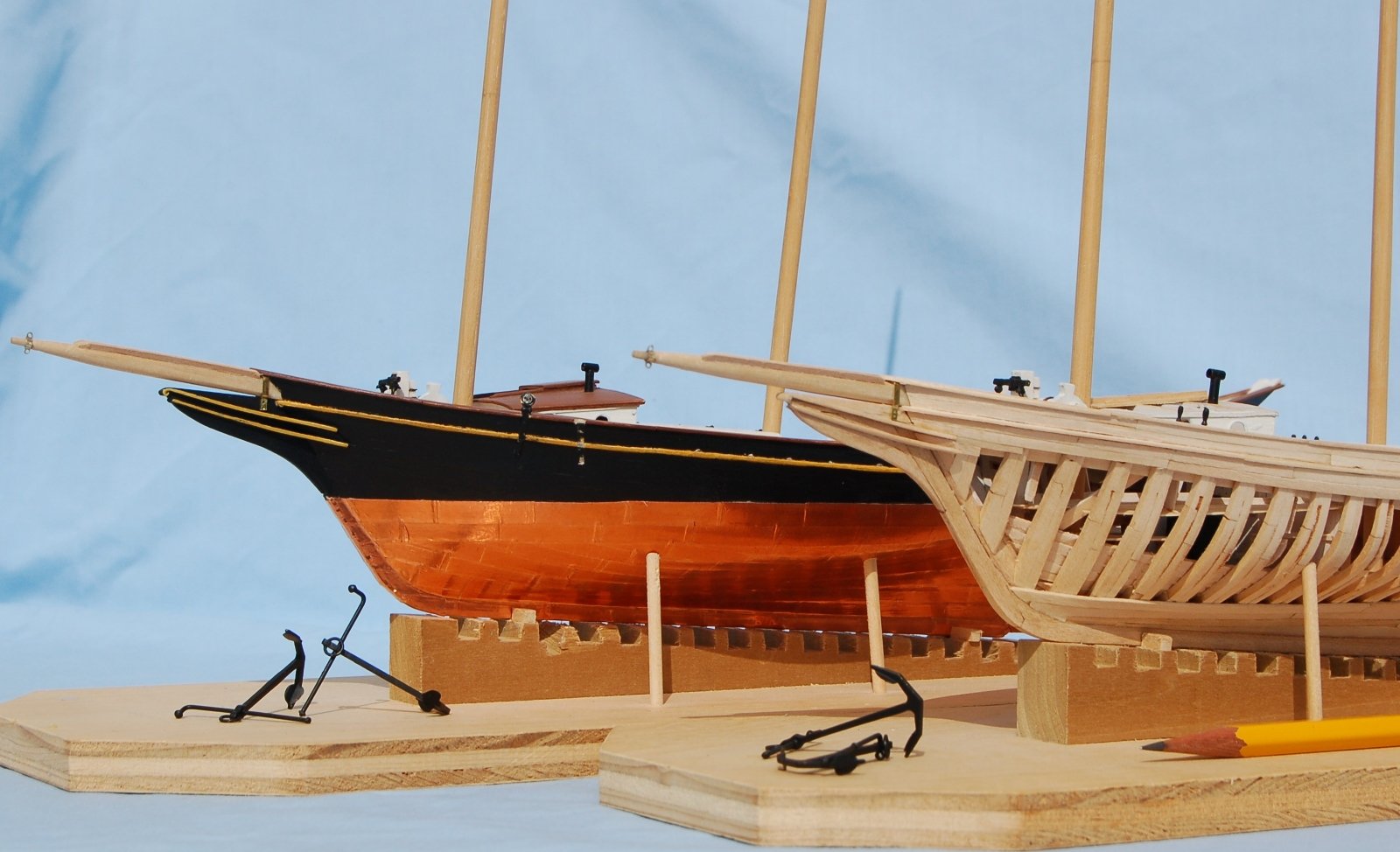
Two Doves, well underway
With two completed kits below my belt, I began searching for a new project. It would be a scratch build. I decided that the project should be challenging but not too challenging, should be not too big and should generally follow along the lines of my previous work. In Chapelle’s The American Fishing Schooners I came across the Dove plans and decided that in addition to being fairly complete plans, the ship itself met my criteria fairly well, somewhat challenging, not too big and like the Prince and the Latham an American built schooner. I purchased a set of plans from the Smithsonian and I was off.
Jim
- Reg, GrandpaPhil, Jond and 8 others
-
11
-
Hello all,
I took my suggestion from a combination of information from Chapelle's Fishing Schooner book and Model Shipways plans for the Latham but don't think the rules are absolute. I'm currently working on the much older schooner Dove also shown in Chapelle's book which has the pins on the boom but appears to use the starboard pin to terminate the main topsail tack.
Jim


Atlantica Sail training ketch by Wintergreen – Scale 1:30 - POF - A smack of English heritage
in - Build logs for subjects built 1901 - Present Day
Posted
Similar in size and complexity to my current project (a pinky) I'll follow yours with interest. Short of the ops with planking thickness, you seem to be making a good start.
I love the photographs. Its humbling to me as a modeler to recognize just how big the actual timbers are compared to the tiny pieces we manipulate in building out models.
Jim