HOLIDAY DONATION DRIVE - SUPPORT MSW - DO YOUR PART TO KEEP THIS GREAT FORUM GOING! (Only 51 donations so far out of 49,000 members - C'mon guys!)
×

petervisser
-
Posts
574 -
Joined
-
Last visited
Content Type
Profiles
Forums
Gallery
Events
Everything posted by petervisser
-
 Hi ZyXuz, The start of your build log sure takes me back to the days when I was building this model. On the whole I was satisfied with the materials, but I did end up buying a number of extra bits and pieces to make a better model. As for the white metal parts, they do bend. Just do it carefully around a curved object of the correct diameter. All the best with your build, and I will follow along. Cheers, Peter
 -
Hi Don, I have some large scale rigging drawings of the Bounty I could lend you. They are John MacKay's which he sold to me some years ago. Otherwise, Petersson's rigging book would be a very good guide. I've been away on holiday this summer so I have taken a break from model building and MSW. We can hook up when I get back from my next trip in early October. A get together is long overdue! Cheers, Peter
- 43 replies
-
- 1
-

-
- finished
- billing boats
- (and 1 more)
-
Hi Ian, I was just catching up with your build log after a long summer hiatus. Stunning work on your Brodie stove! If the rest of your model receives the same amount of attention, you will end up with a truly amazing model. All the best with the rest of your build! Peter
-
She looks great Dan and a bit of sanding should give the wood a nice finish. Looking forward to the hull treatment already! Cheers, Peter
-
Hi Dan, A very nice start on your Bounty. All the best with your build and I will follow with interest. Cheers, Peter
-
Hiya Mike, Yes, the lack of boats for the kit are a bit out of the norm and I considered adding some to my own model. I reconsidered because of the fact that they would hide the details of the gun deck. I spent a goodly amount of time rigging those guns down there and it would have been tragic to then cover them up with boats on the booms! As for the "documentation" that accompanies the kit regarding the build dates and designer, it is best to ignore it. Corel did not have access to the interwebby when they first produced the kit and put something together on the fly by the looks of it. As for my own build, I used John McKay's and Ron Coleman's Anatomy of the Ship Book "Pandora" to help me with the layout and design features concerning the deck fittings. Like you I was less interested in a totally accurate build of the Unicorn and more interested in creating a reasonably accurate frigate of the time. Pandora was similar in size and age. Hope this is a help. Peter
-
Hi Mike, I have built the Unicorn and finished it only last year. As for the guns, Corel have not really provided the hardare to make an accurate model. As far as I know those frigates were designed to carry 24 x 9 pdr. guns, but then added 4 x 3 pdr. guns to the quarter deck. This is how I built it. I bought some after market guns which were smaller than the guns provided to indicate the smaller calibre. I just eye-balled it and did not do any real calculations. As for the rest of the model, I improvised here and there to make the model appear more accurate to a frigate of the time. As posted earlier, Corel have cut some corners and taken some liberty in designing a kit that is less than authentic. However, the basic materials are of a good standard as you have discovered with your new kit. Now its up to each individual model builder to put the bits together to his or her personal satisfaction. I myself bought some better blocks here an there, used different rigging thread, changed out the ship's wheel and altered the deck layout a bit. All in all a very satisfying project and one I am proud to display. Good luck with your own Unicorn, and I will look for your build log when you get around to her. If I can help in any way, just let me know. Peter p.s. Thanks Ian for all your kind words.
-
Superb looking model thus far Chris. And yes your ship's boat turned out very well too! All the best with the rest of your build. Peter
- 69 replies
-
- 1
-
-
- fly
- victory models
- (and 2 more)
-
Hi Channel, I just caught up on your build log. Wow, your attention to detail is really showing. Very interesting project, to be sure. It will be very cool to see Bismark and Arizona side by each and compare their different designs Keep up the excellent work! Peter
-
Hi Phil, Glad to see you are still hard at it with your Bounty. Very nice work indeed. I especially like your re-working of the figurehead. She has way more character, and pops out now. In more ways than one... Peter
-
Hi Ian, I struggled with the decoration around the quarter galleries as well. I could not figure out how to attach the lower mouldings to the model. I had them all painted and when it came time to attach them, I was left scratching my head. I took the easy way out and simply left them off the model. Not too creative, I must admit, but effective! It didn't seem to detract from the model overall. I'll be interested to see what your solution ends up being. Good luck! Peter
-
Hi Gil, Yes, I plan to be here next year. Hope to see you then. Have a wonderful cruise along the "Best Coast". Peter
-
Hi Michael, It was a real pleasure to look in on your build log and view the pics you have just posted. They look amazing. I can start to imagine the finished product, and you will have built something special when you have it completed. Keep up the exceptional work! Peter
-
Hi Gil, If you happen to pass through Bella Bella/Shearwater in July, feel free to pop in. I'm at the life boat station here. We can compare boats... Happy travels! Peter
- 755 replies
-
- 1
-
-
- finished
- caldercraft
- (and 1 more)
-
Hi GG, Great build log so far. All of your pictures and descriptions are first rate. I have always admired this kit and will follow along with interest. Peter
-
Hi Ferit, I have enjoyed looking through your build log. Beautiful craftsmanship and your attention to detail is impressive. Keep up the great work. I look forward to seeing more! Peter
-
Beautiful lines on your Mars Robert. She looks great! Peter
-
Great work Derik! Really enjoyed your log so far and am looking forward to following along. Cheers, Peter
-
I just caught up with your build log. Very impressive work and your attention to detail is amazing. Great photos as well. Thanks for submitting them and letting us learn from your methods. Peter
-
Hi Ian, I believe we corresponded on the old MSW site over the Unicorn. I completed mine just last year in the record time (I thought) of 15 years. You have out-paced me, so I have read from your build log. I remember buying this kit because of the fact that it was a frigate. I learned early on that it was not an accurate model and the description given by Corel was way off. However, it was a frigate and I charged ahead. Reading what little research I did, I made some minor modifications regarding the smaller calibre guns on the quarterdeck, and re-arranging some of the deck furniture and fittings. I also fitted some proper pin racks at the bases of the masts. I used John MacKay's book on the Pandora to help me with some of the details. It was good fun and I enjoyed the build. You are certainly doing your homework and will have a much more accurate Unicorn than I have. There are some completed model photos in the gallery if you care to take a look. Good luck with your build and I'll be sure to check on your progress from time to time. Cheers, Peter
-
Thanks Andy. I can't take credit though as I copied the colour scheme from the box. Keith, those are storage lockers for the Heineken. Peter
-
This model is very lucky to have found you. Andre, you are doing a wonderful job restoring this once sorry Wasa. The original builder would never recognize this model again. Thanks for posting your log. Peter
-
A stunning piece of work Rusty and really inspirational. Thanks for sharing all the great pics! Peter
-
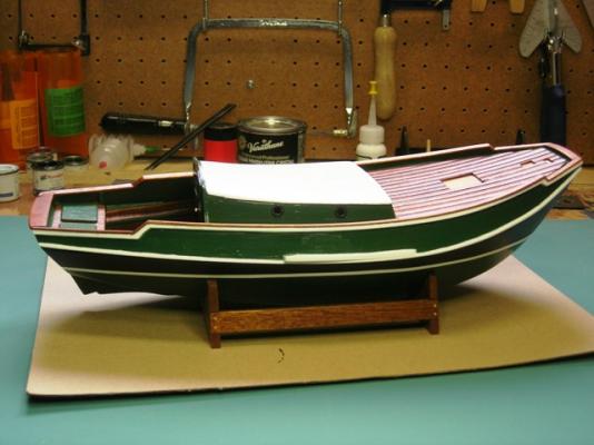
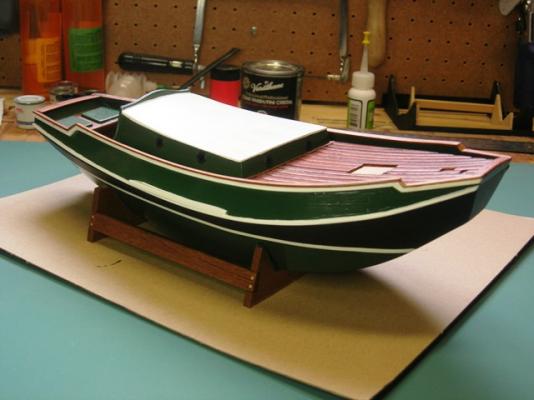
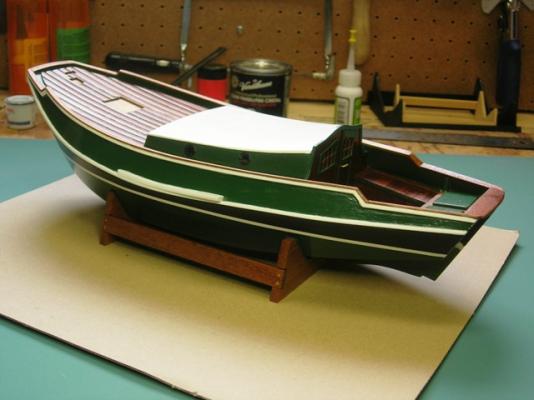
I am now up to date with my build log of the zeeschouw. The posts will now become a little sparse as it is at home and I am at work, far away... With summer coming the construction will slow right down I'm afraid as the "boss" has other ideas as to how I should spend my spare time. Damn bosses... Anyway here are some more pic's. Happy modelling! Peter
- 109 replies
-
- 3
-
-
- zeeschouw
- billing boats
- (and 1 more)
-
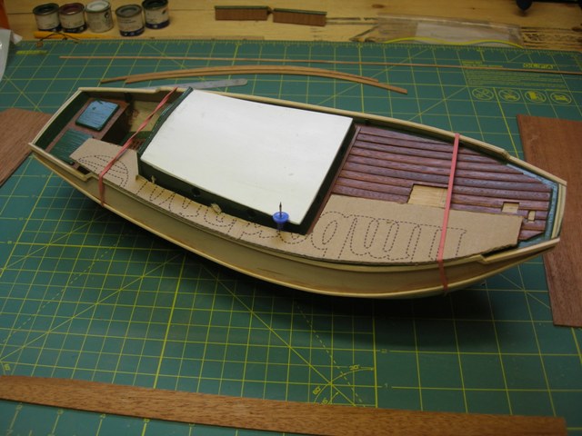
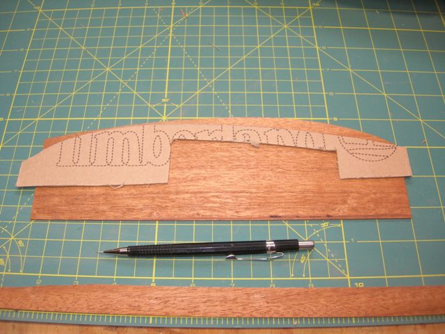
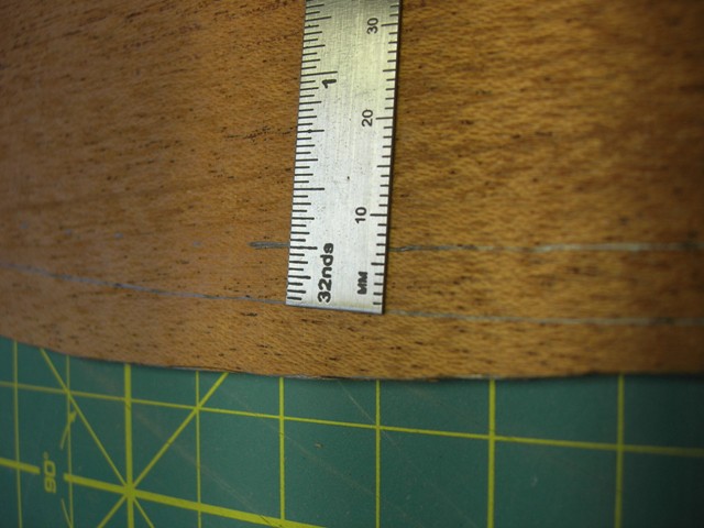
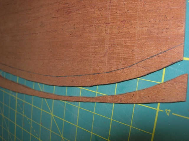
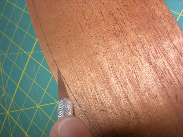
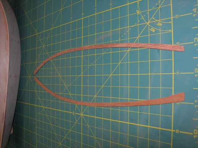
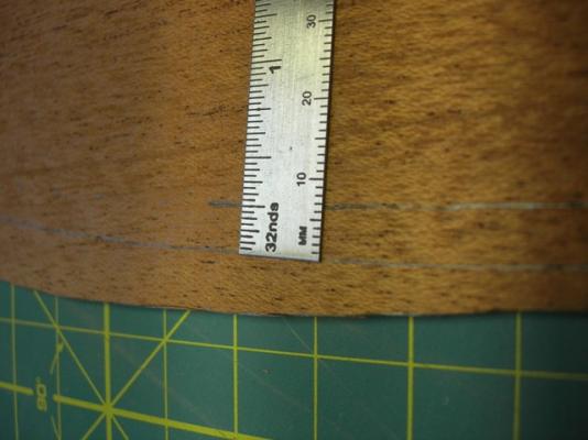
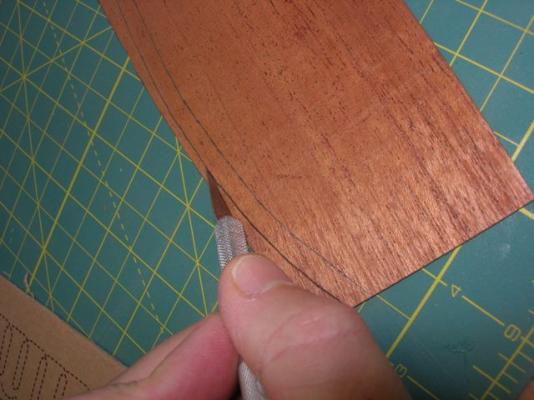
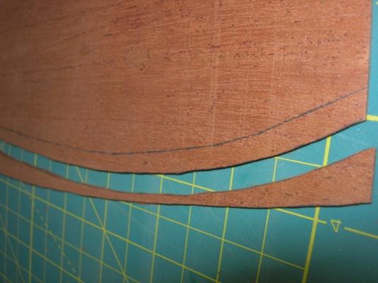
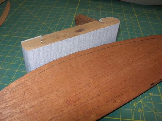
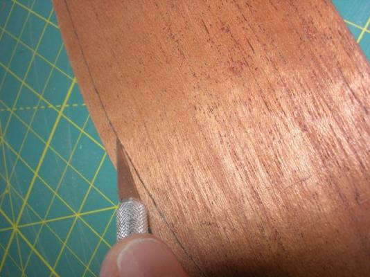
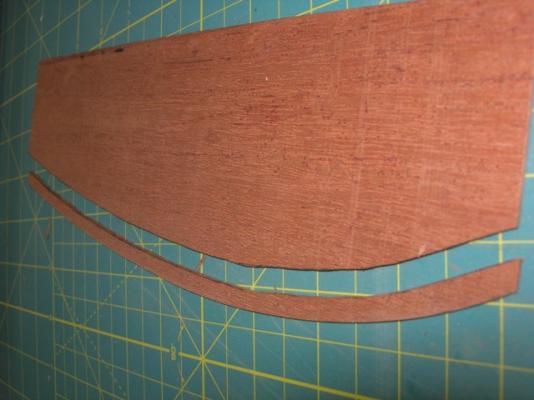
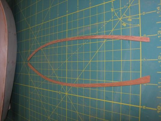
Thanks for looking in gents. While coat after coat of paint go on the hull, I was side-tracked with getting the cap rails ready. Nothing finishes off a hull like a good cap rail! I kept the design and construction simple. No scarph joints for me this time around. It is a skill I have yet to master and if anyone can point me in the right direction in that regard, I'd be thankful. My method was to try and get the outside curve onf the gunwale transferred to a sheet of mahogany. For this I used a thin sheet of cardboard and held it to the gunwale so that I could trace the curve with a pencil. I then cut the cardboard along the pencil line and then laid that over the mahogany and did another trace. Too easy! The pictures will show the process... Here you can see the cardboard cut and conforming to the curve of the gunwale. I had already cut it and re-applied it so you can see the result better. Now the cardboard is laid on the sheet of mahogony and the shape is traced onto the sheet. I decided on a suitable width that would allow for a bit of sanding on both edges. I cut the mahogany with an X-acto knife working from the end and then progressively towards the other end. This avoided awkward splitting of the sheet. A little rough around the edges, but the sanding block will take care of that. This is one of my favourite tools! Now for the inside cut. Again work backwards with the X-acto knife, otherwise the sheet will likely split along the grain. Now to sand the inside curve to even the width of the cap rail. Here they are, ready to be glued onto the gunwale. These strips are for the mid-sections of the model. There are short pieces to go on the ends, which were prepared seperately.


- 109 replies
-
- 1
-
-
- zeeschouw
- billing boats
- (and 1 more)