DONATION DRIVE - SUPPORT MSW - DO YOUR PART TO KEEP THIS GREAT FORUM GOING! (91 donations so far out of 49,000 members - C'mon guys!)
×


FriedClams
-
Posts
1,368 -
Joined
-
Last visited
Content Type
Profiles
Forums
Gallery
Events
Everything posted by FriedClams
-
 Nice progress OC. Hope that the tests went well and that your wife is feeling better. Gary
 -
F-86F-30 Sabre by Egilman - Kinetic - 1/32nd scale
FriedClams replied to Egilman's topic in Non-ship/categorised builds
Wonderful progress on this bird EG, and as always, an educational thread with interesting topics. Looking good! Gary -
Just catching up Grant, and what a fantastic job you're doing on this model. The fitting, coloring, weathering and all the little touches look great! Keep at it and keep it coming. Gary
- 333 replies
-
- 11
-

-
Excellent sub-atomic modeling once again Wefalck! What an exercise in patience that must have been. Very nice. Gary
-
Just catching up Marc, and I'm sorry to hear of the Covid and the unprovoked attack. Glad you are well now and recovering. Excellent progress on the model and your attention to the smallest details is inspiring. Very nice work! Gary
- 2,699 replies
-
- 5
-
-

-
- heller
- soleil royal
- (and 9 more)
-
Congratulations on finishing your wonderful model Nils. The details tell a story and add so much to an already beautiful boat. Well done. Gary
-
Just catching up, and what beautiful modeling you've done Keith! Such clean, precise and detailed work. Happy to hear that you're planning a new build and to me, your candidate is a great choice. The engine room details would be unique and a surprise visual draw. But I do also agree with the other members that Ena is a real looker. Whatever you end up building will no doubt be extraordinary. Gary
-
She turned out beautiful Paul - congratulations! I like that the roof pops off the wheelhouse and the burlap sacks are a nice detail. Clean and crisp construction. Well done. What an amazing coincidence pulling out that magazine article. Sort of Twilight Zone. Gary
- 100 replies
-
- 1
-
-
- pauline
- BlueJacket Shipcrafters
- (and 1 more)
-
Beautiful work Chris. Another great looking card model! Excellent. Gary
-
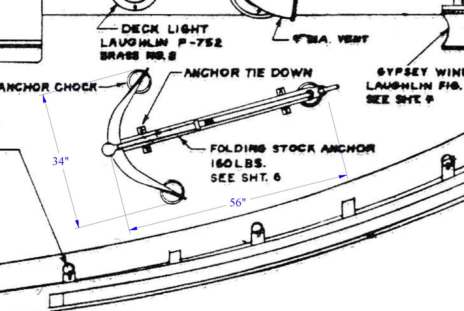
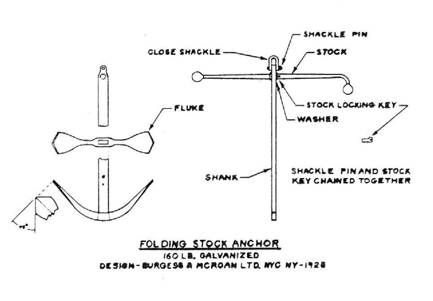
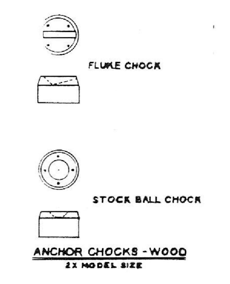
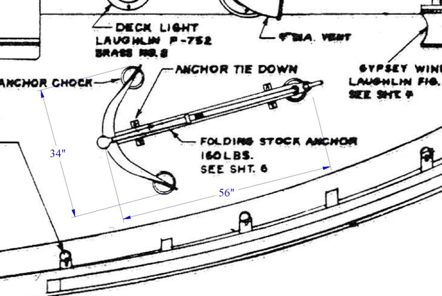
Hello Paul. Your sardine carrier looks great. Here is some related information on the anchor that may be of help to you. I scratched the William Underwood carrier years ago and here is what the plans from Harold Payson called for. It's a 160 lb admiralty kedge anchor. The Underwood is 70 ft LOA and the Pauline is 83 ft LOA, so yours would most likely be a little larger. But they are from the same era. Here's a webpage that might help in sizing the anchor, its weight and dimensions. Note that everything is in metric. https://www.tullyn.com/product/admiralty-anchor/ Here's a few drawings from the Underwood. Hope this helps. Looking forward to the final glamour shots. Gary


- 100 replies
-
- 2
-
-
- pauline
- BlueJacket Shipcrafters
- (and 1 more)
-
Brig Le FAVORI 1806 by KORTES - 1:55
FriedClams replied to KORTES's topic in - Build logs for subjects built 1801 - 1850
Very time-consuming work - but it is going to look so great! Gary -
Hello Andy, I saw some activity at this thread, so I stopped in to see what was going on. I have been watching Louis Sauzedde for a long time and have spent countless hours watching his videos on boat building. What a master he is - from selecting wood to the fit and finish, such detailed information. I didn't realize he was starting an Orca build, so thanks for the heads-up. I will definitely follow that. Waiting for your next build, soon I hope - done with the Parthenon? Gary
-
Hello Grant. Just found your log and it looks like a terrific project. SierraWest has a great reputation for high-end kits though I have never built one or even seen one in person, so I'm very interested in following your progress. You are certainly off to a great start and I'm certain this will be fabulous build. I agree with you on the chalk/alcohol method for coloring and weathering wood. The process is easy to control and variations of all sorts (be it subtle or aggressive) are simple to add and blend. There are a number of commercial products out there that are very good at staining wood, but I haven't seen any that work better. I know many modelers who swear by a product called Silverwood that was manufactured by Builders in Scale. They sold the business years ago to a company called CC Crow and I understand availability can now be spotty. Never tried the stuff. Pigments and alcohol are also a great porous surface colorant albeit a bit heavy-handed - great when you want deeper richer tones. Loved your steam pumper project and I'm looking forward to this one. Gary
- 333 replies
-
- 10
-
-
Roter Löwe 1597 by Ondras71
FriedClams replied to Ondras71's topic in - Build logs for subjects built 1501 - 1750
Beautiful work Ondras! Gary -
Nice Keith! The silhouette is a delightful image - so peaceful and evocative of a distant time. Gary
-
Catching up on your log is always a pleasure, and your research is wonderful and such an interesting read. Thank you Marc, for sharing this with us. Hope your relocation is going smoothly. Gary
- 2,699 replies
-
- 3
-
-
-
- heller
- soleil royal
- (and 9 more)
-
It's been a while since I've visited your build Nils, and boy this model is coming along and looking great! Love that engine! I remember back a year or so when you constructed it, and I wrote into my notes your use of a wristwatch cover sealing O-ring for the belt - such a clever and resourceful idea. Nice looking fish too. Gary
-
Good to see an update on your Bluenose Richard - really very nice furniture/cabin work. Love your shop. With a frig and a cot, there'd be no reason to ever leave. Gary
-
Good grief Valeriy - such excellent modeling - you are in a class by yourself. Love those boats (along with everything else on this model). So inspirational! Gary
-
Good to see an update on your sardine carrier Paul. Your model is looking great! Good solution. Whenever I'm building a model with a lot of lines on it, I always plan and depend on one last line that I use to tension all the rest. I have a deep reservoir of cuss words, but when I've exhausted all of them, I find arranging them in novel combinations helpful. Good to hear you've been enjoying your 1:1 boat. Looking forward to future updates. Gary
- 100 replies
-
- 1
-
-
- pauline
- BlueJacket Shipcrafters
- (and 1 more)
-
Nice update Brian - great work all around! I'm no expert on the matter, but I often find that when the color or overall look is wrong, it's because the white balance is off. Often the camera is confused by a mix of lighting conditions such as artificial light mixed with natural lighting. Try manually setting the white balance on the camera or correcting it software by pointing to what you know is a white or neutral gray spot in the image. Also, because there is a lot of black on your model, the automatic exposure may be overcompensating and washing out the colors. Try stopping it down. My two cents anyway. Like Eric, I too admire snakes - but I wouldn't want them in the house. If it happens again, show real dominance and make a pair of carpet slippers out of him. Then walk around outside with them on. Terrific work on this model - very nice, clean and exacting. Gary