HOLIDAY DONATION DRIVE - SUPPORT MSW - DO YOUR PART TO KEEP THIS GREAT FORUM GOING! (Only 20 donations so far - C'mon guys!)
×


FriedClams
-
Posts
1,368 -
Joined
-
Last visited
Content Type
Profiles
Forums
Gallery
Events
Everything posted by FriedClams
-
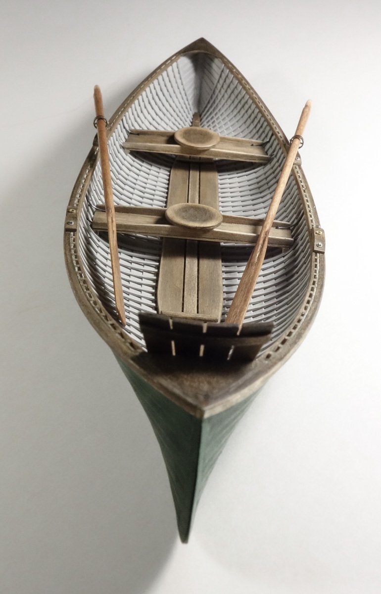
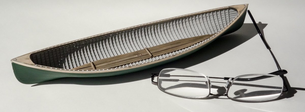
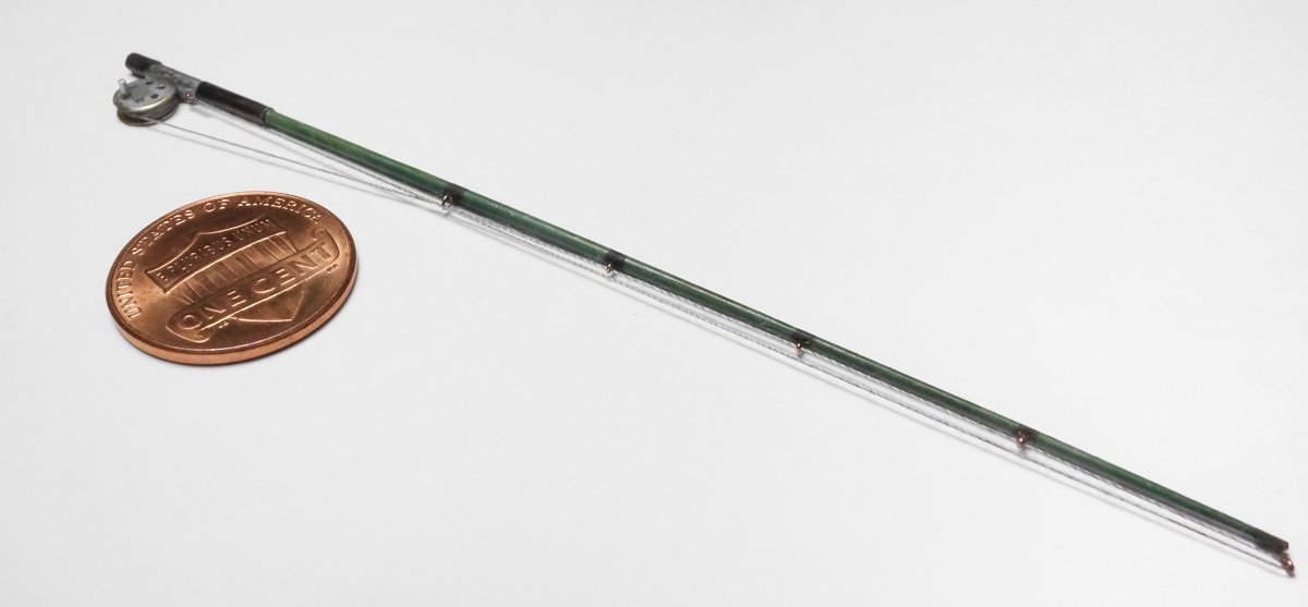
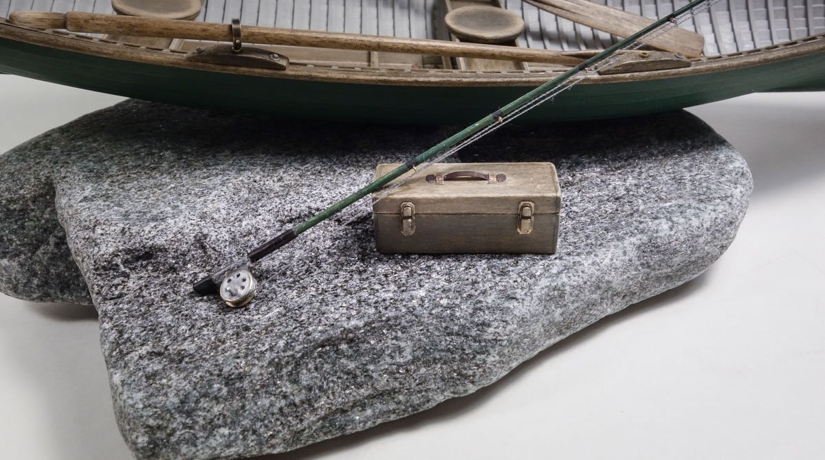
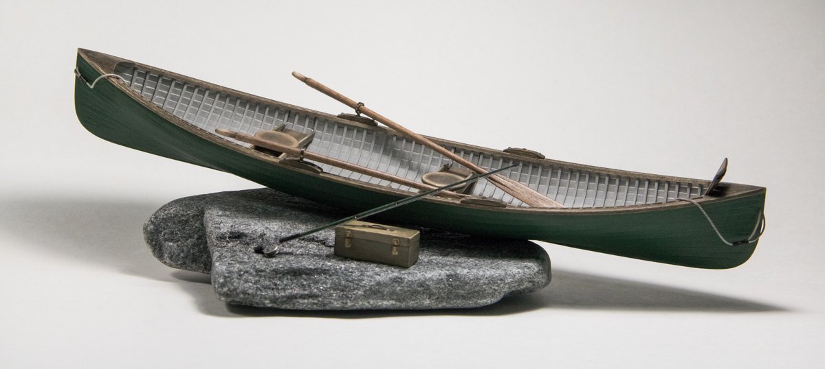
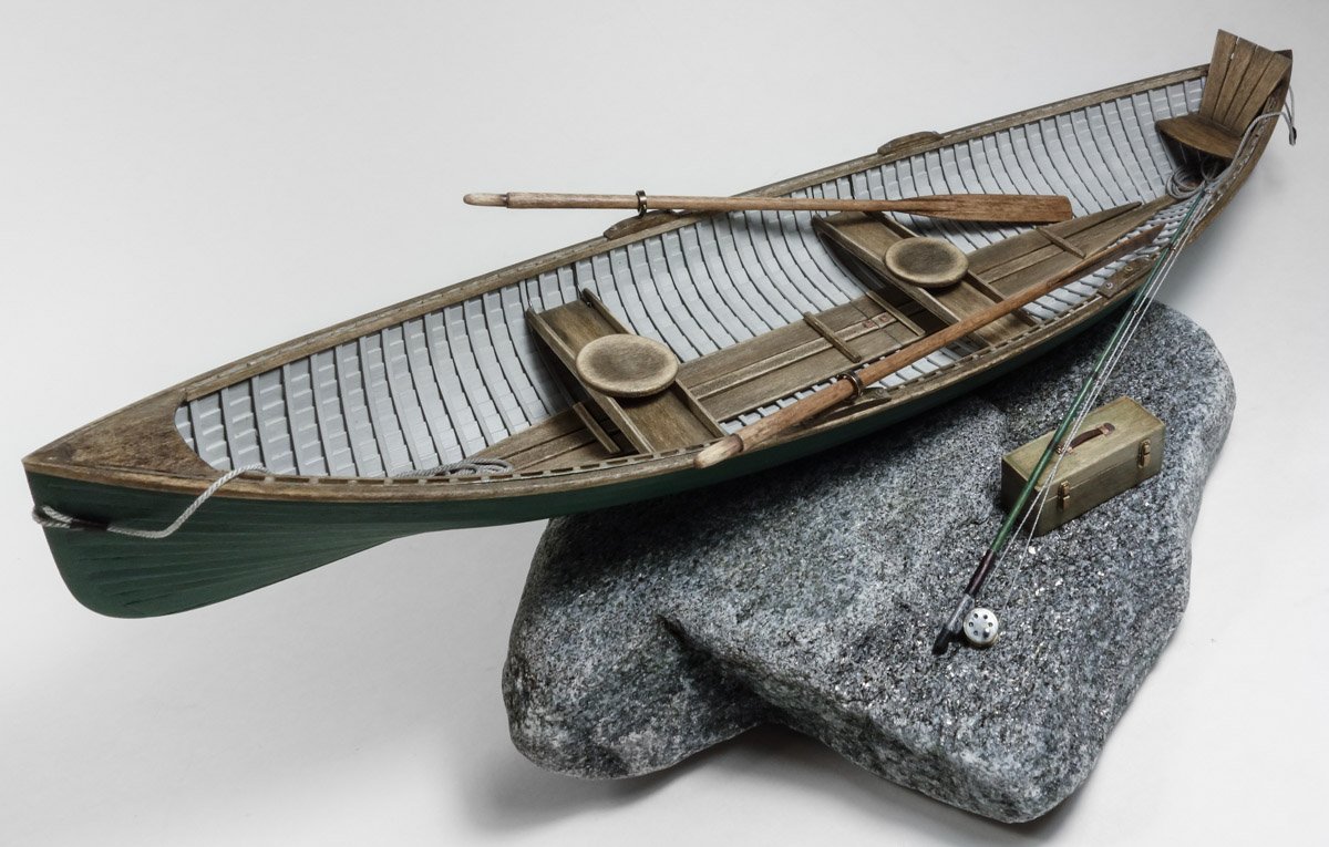
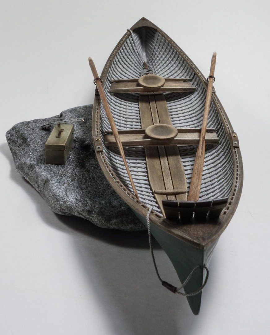
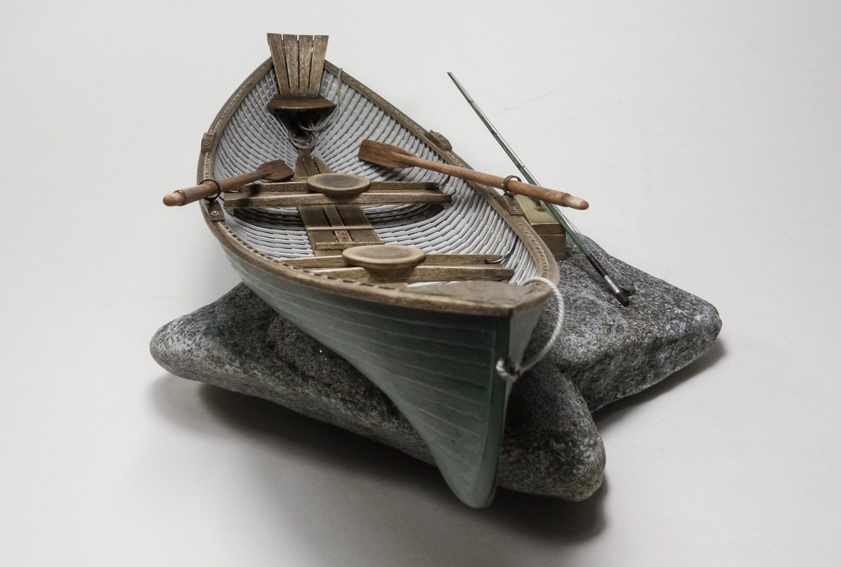
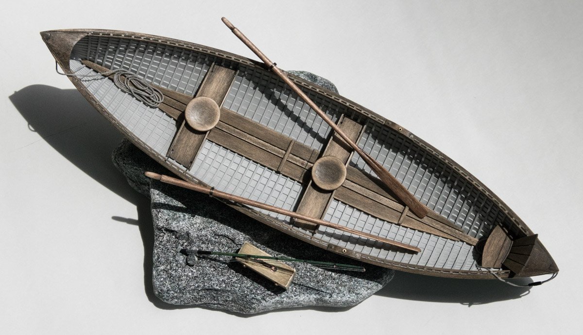
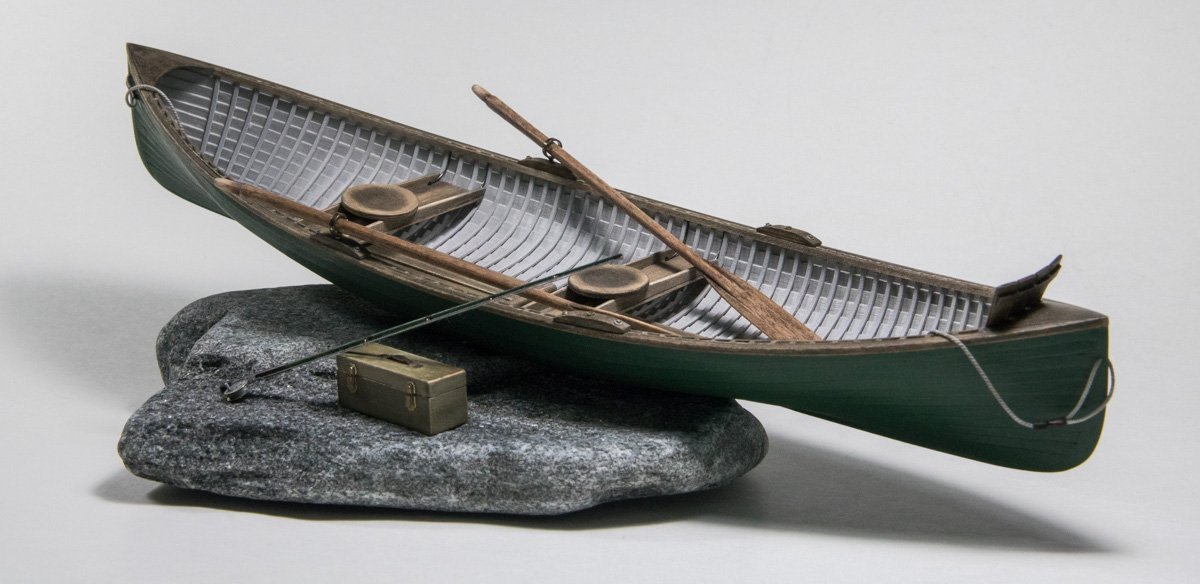
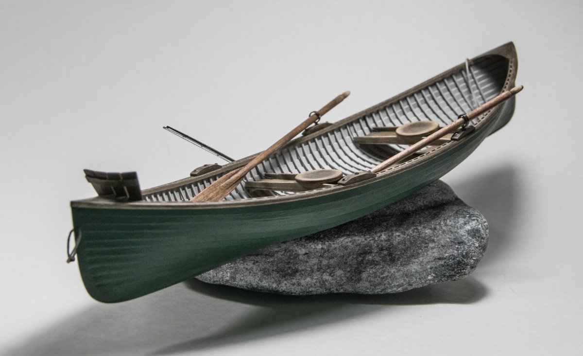
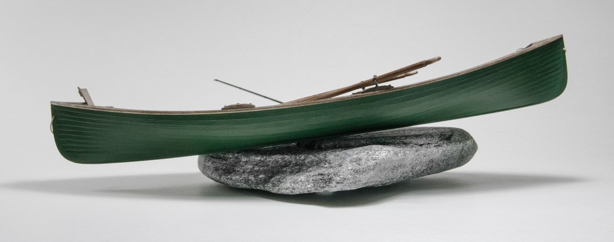
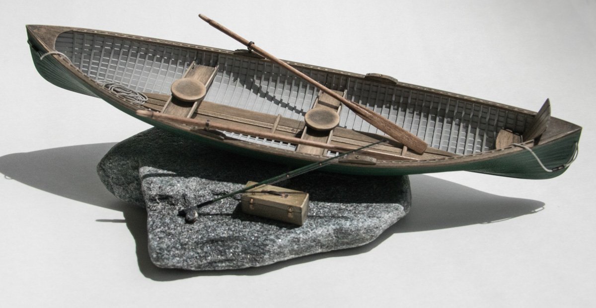
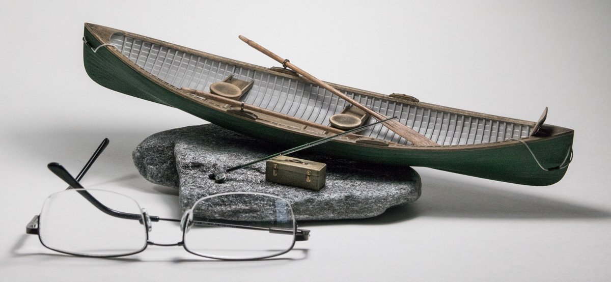
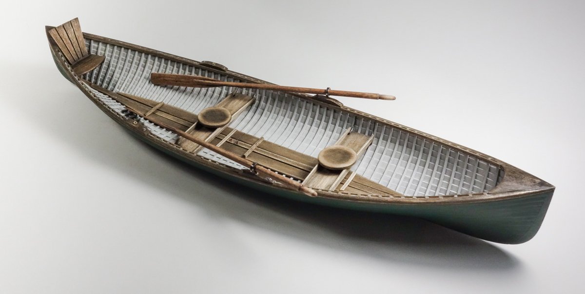
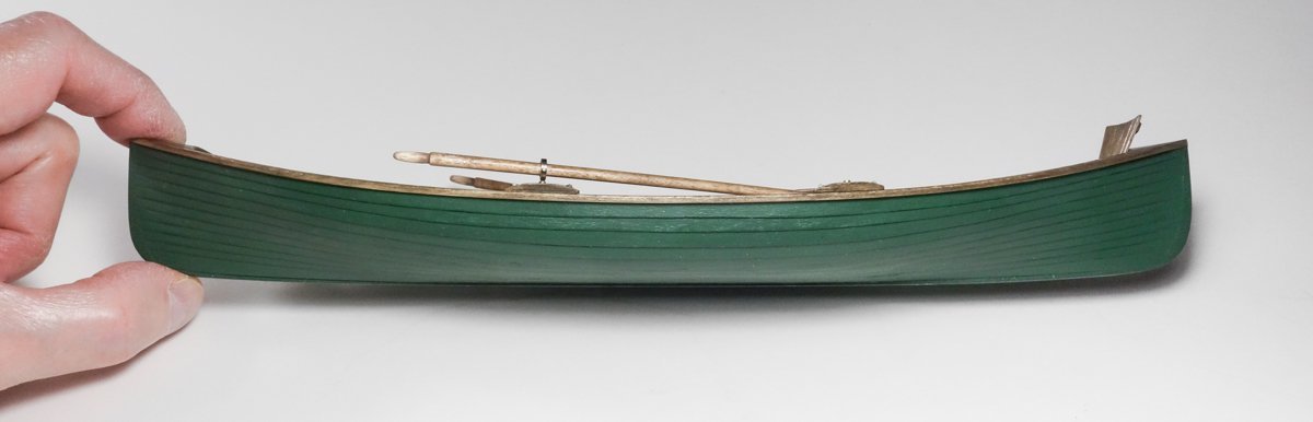
 Greetings fellow modelers. A belated thank you to Keith, Kev, Andy and Ron, for your comments. How has an entire month gone by unnoticed? I am sure you are correct on this point Kev. It wouldn't take more than one or two complaints from clients about a sore bottom for the guide operators to fix that. Thanks for checking out my log and for the nice words. Hello Ron. Thanks, I didn't know about these epoxy rivet decal sheets, but I can think of many possible future uses. Finished I've been working on this Rangeley model in fits and starts between outdoor projects and other activities. But it is finally complete. A couple of minor details have been added. A fly rod and reel made of wood, brass and paper. And a tackle box of wood, styrene and brass. Exposed rock ledge is visible everywhere in Maine and I reasoned it would make an appropriate base for the model. Both ends of the boat got stern/bow lines. I chipped high points off the rock until it sat flat without rocking and then attached felt feet to keep it from destroying our furniture. Also, I epoxied a label to the underside. The hull received a final coat of paint and everything was epoxied to the rock. Thanks to all for stopping to take a look and for the “likes”. And I especially want to thank everyone who has left comments. Your thoughts, suggestions and support are always greatly appreciated and I thank you so much. Be safe and stay well. Gary
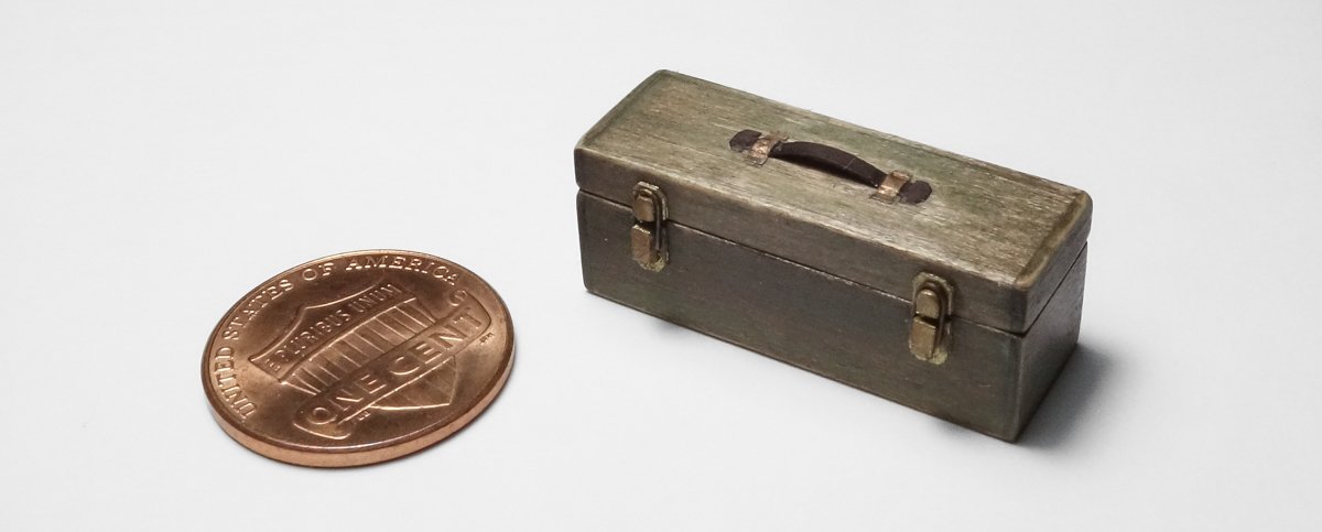
- 79 replies
-
- 31
-

-

-
Keith, this is such heartbreaking news. I am so sorry for your loss. My heart goes out to you and your family. Gary
-
Brig Le FAVORI 1806 by KORTES - 1:55
FriedClams replied to KORTES's topic in - Build logs for subjects built 1801 - 1850
How small and intricate! Beautiful work indeed. Gary -
Ouch and Phew! Gary
-
Very nice work Keith - they look terrific! And like Brian, I don't see this clutter you speak of either. Gary
-
Great work John. That last photo on post #43 is amazing. Clever process on the deadeyes - thanks. Gary
-
Thanks to all for the likes and for stopping by. Thank you, Tom Thanks Keith. All I had to do was execute someone else's design, and a voice in my head kept whispering to me “keep it simply stupid”. So that's what I tried to do. It's true, I'm being something of a fussbudget on the outer hull – but just one more thin coat of paint and . . . Oh, and "a rippled blue surface of cattails and waterfowl" sounds wonderful. Hello Wefalck, and thanks. Yes, the seats are different and virtually every period boat had them. I have read the intention was to keep inexperienced customers centered in the boat. Having never sat in one, I can't comment on the comfort, but I imagine the comfort level was inversely proportional to how 'broad across the beam' the customer was. I'm always amazed how many working boats that were designed and built to be strictly utilitarian, are also handsome and appealing as well. I'm not sure how much you would enjoy fishing the Rangeley Lakes – there are no 'Great Whites' there you know. Thanks FF. Thanks Druxey - It's been a fun model to build. Thanks so much Keith - if only it had rivets. I'm in the middle of several "landscape improvement" projects, but still hope to have a completed model posting in a week . . or so. Thanks and stay well. Gary
-
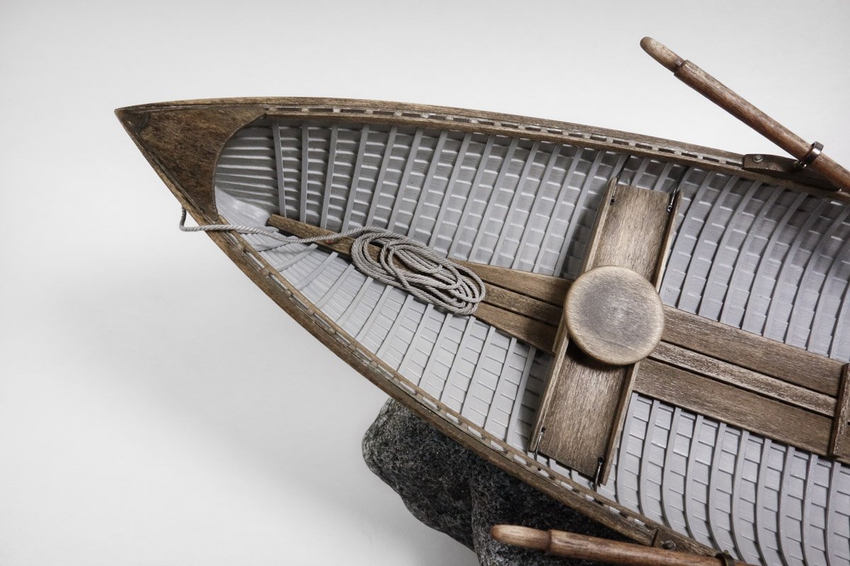
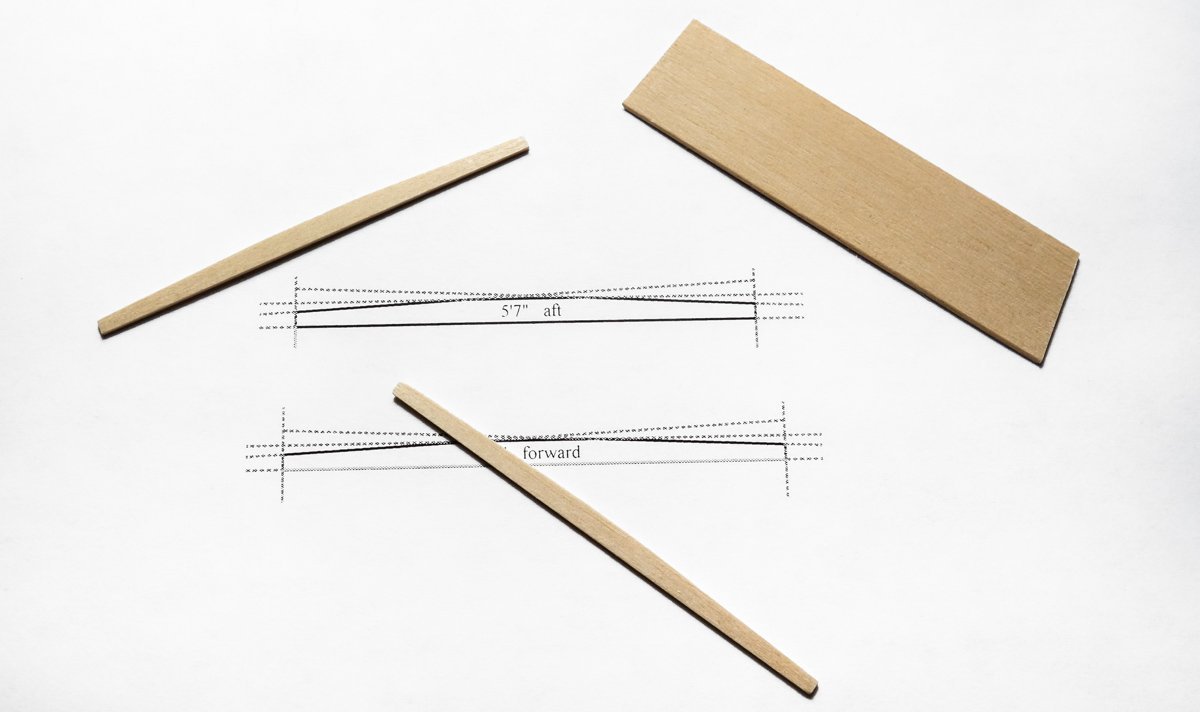
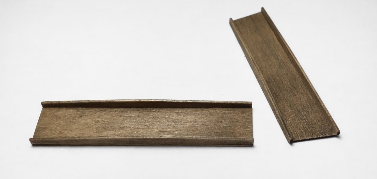
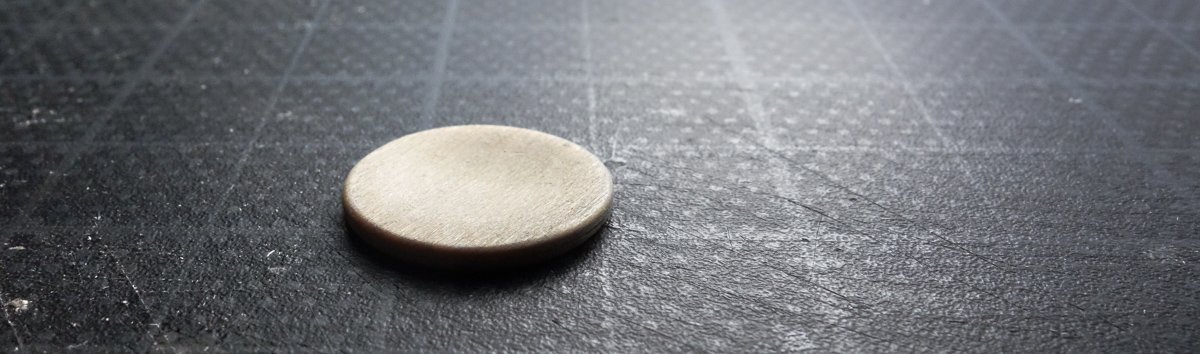
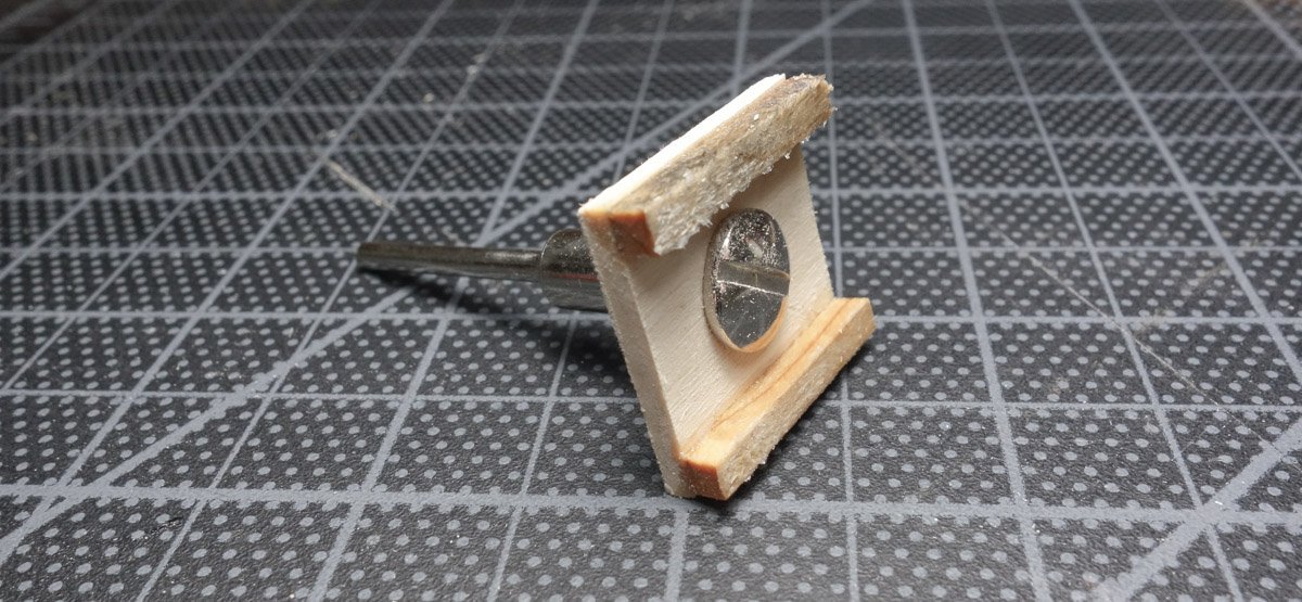
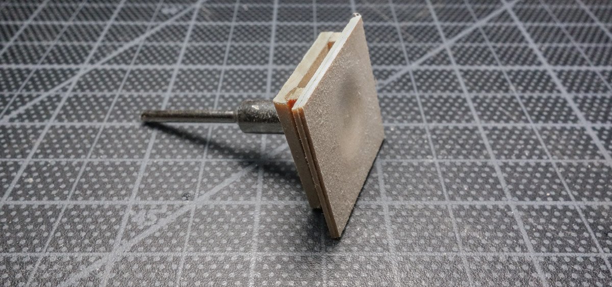
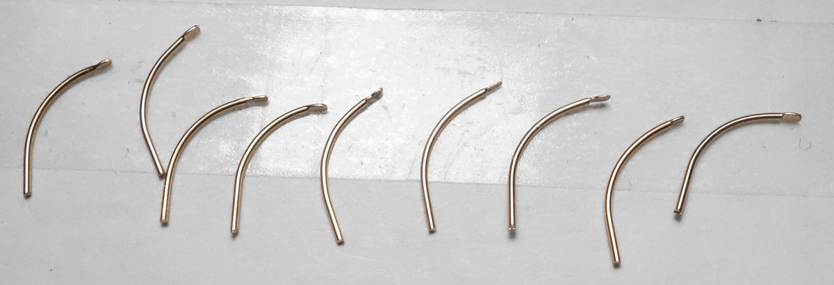
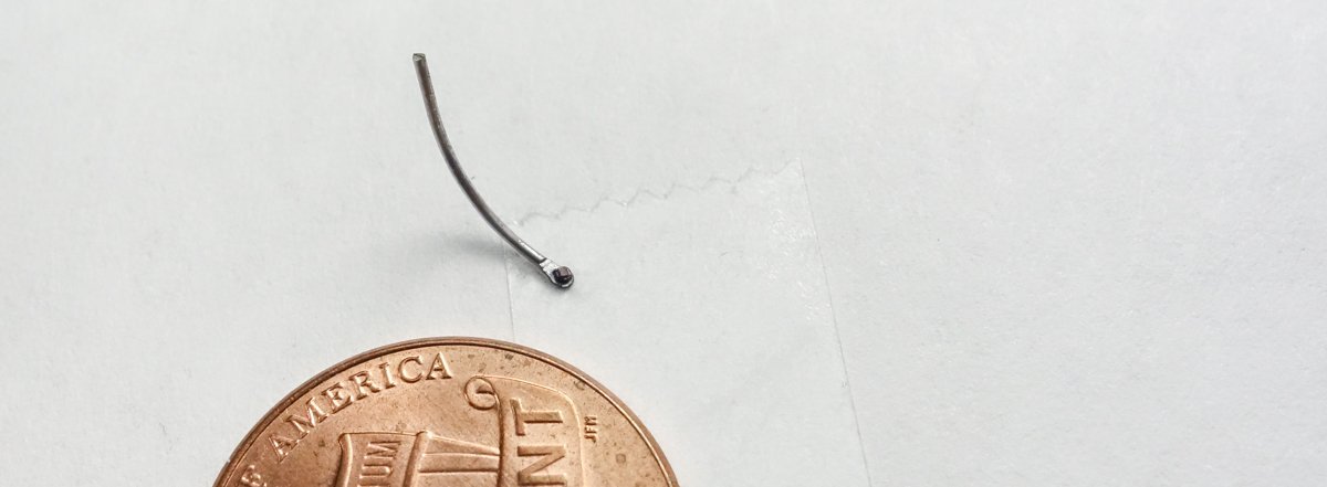
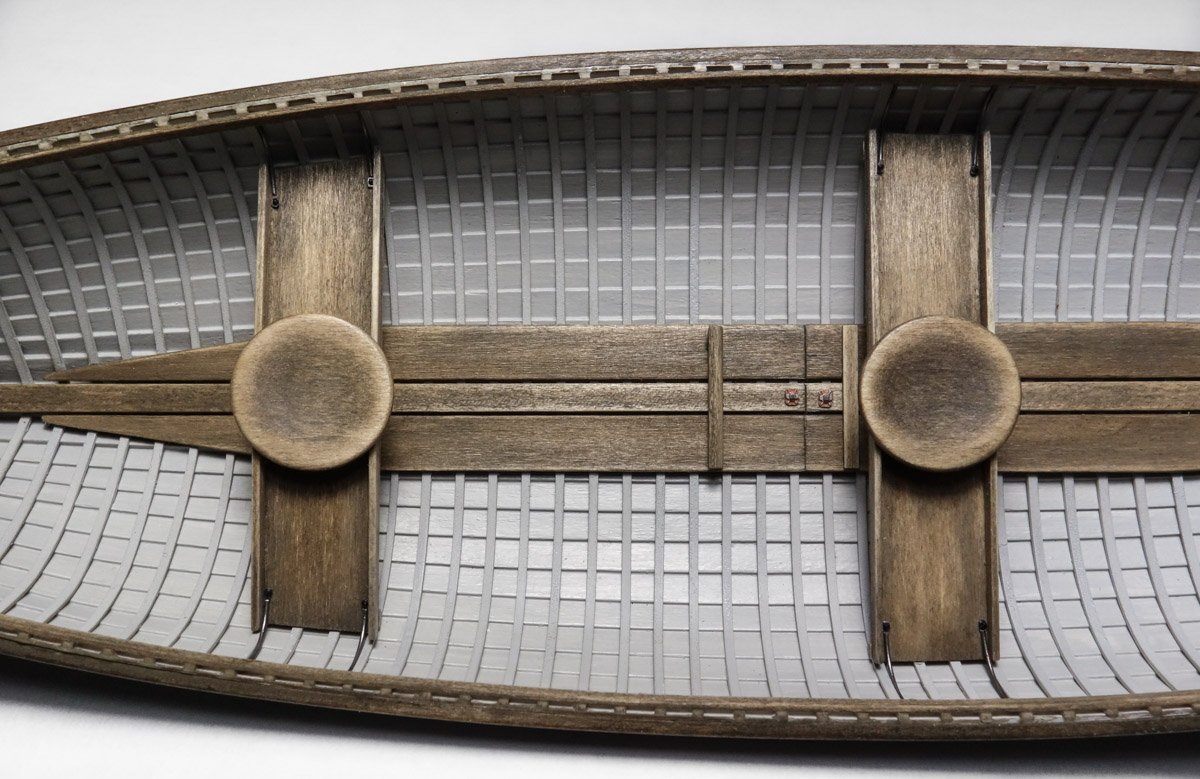
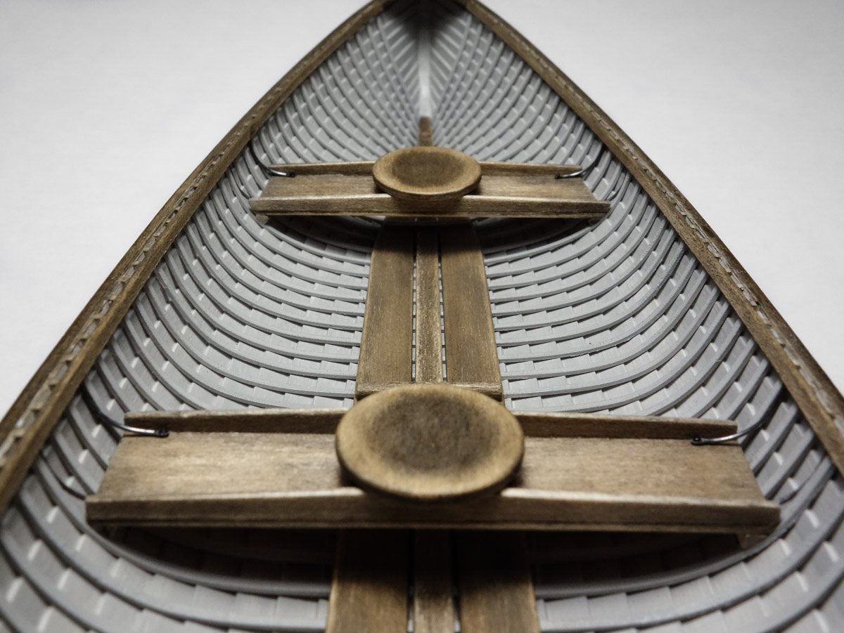
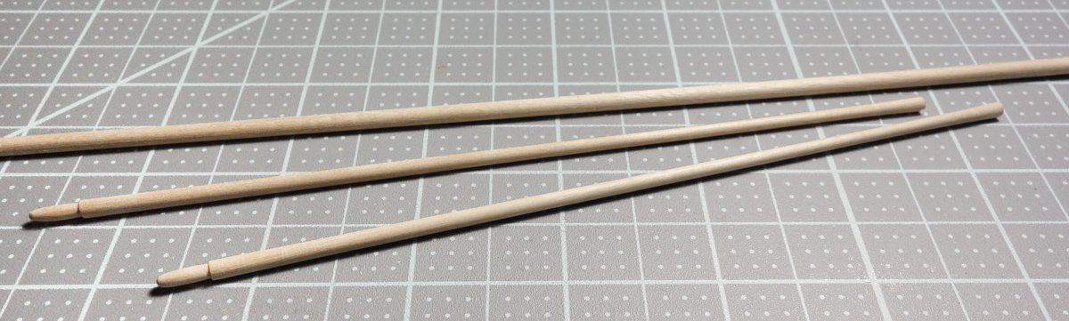
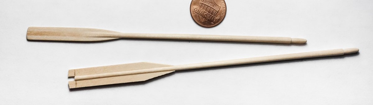
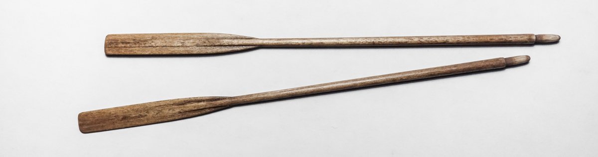
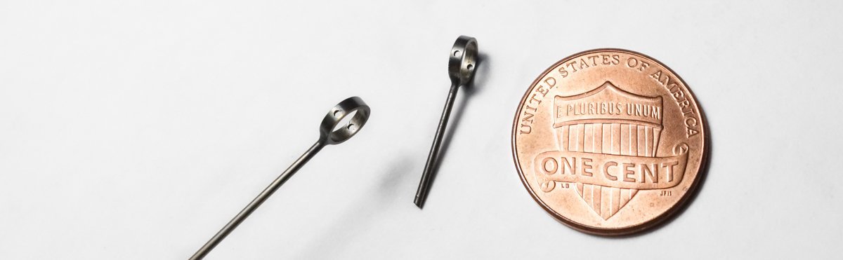
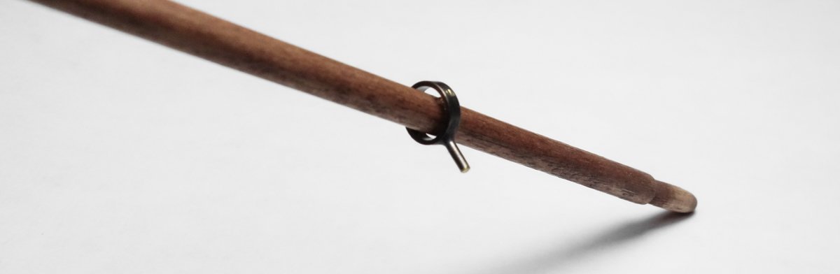
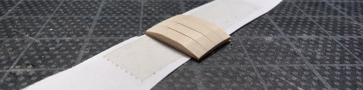
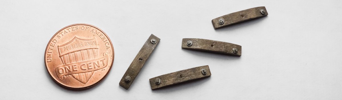
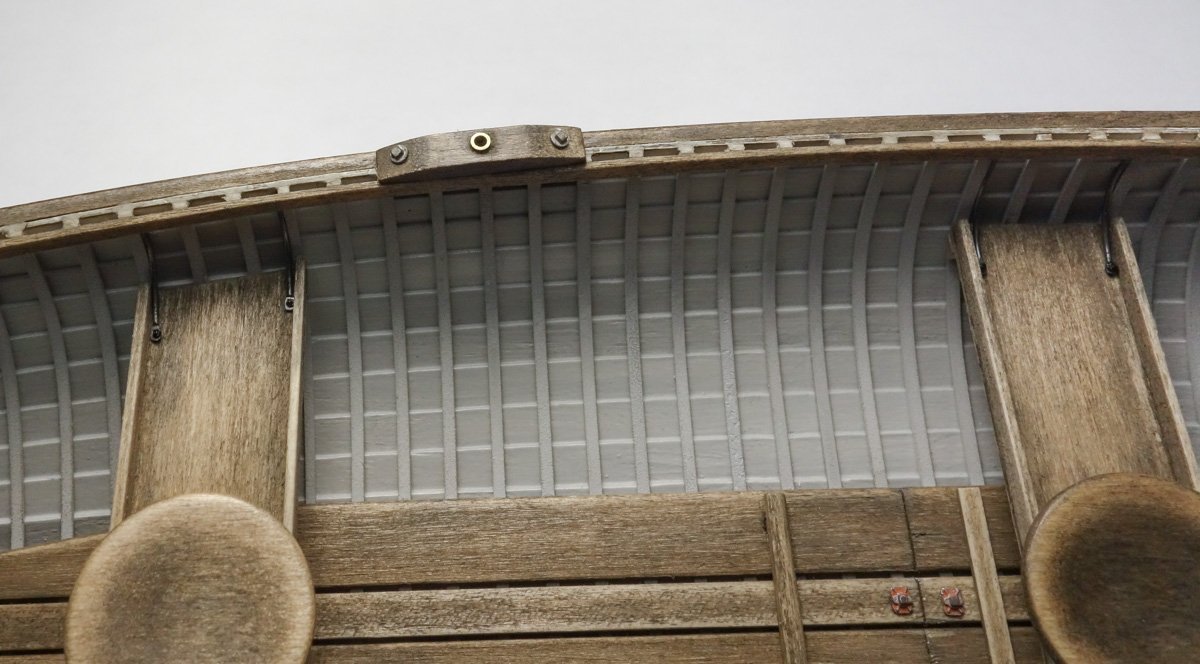
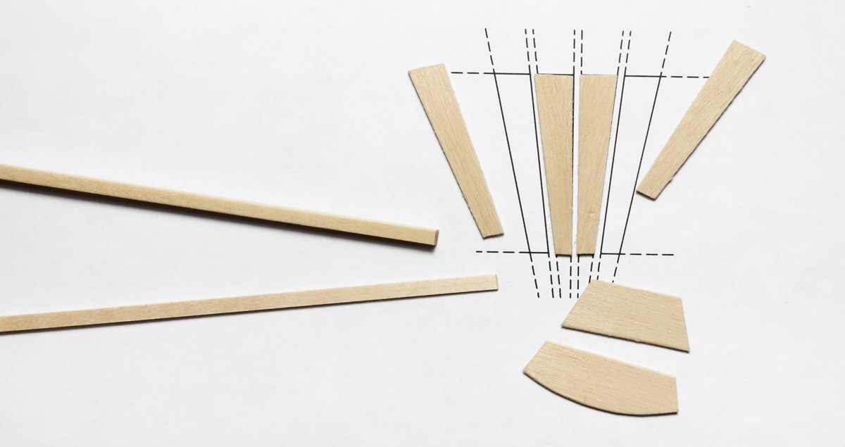
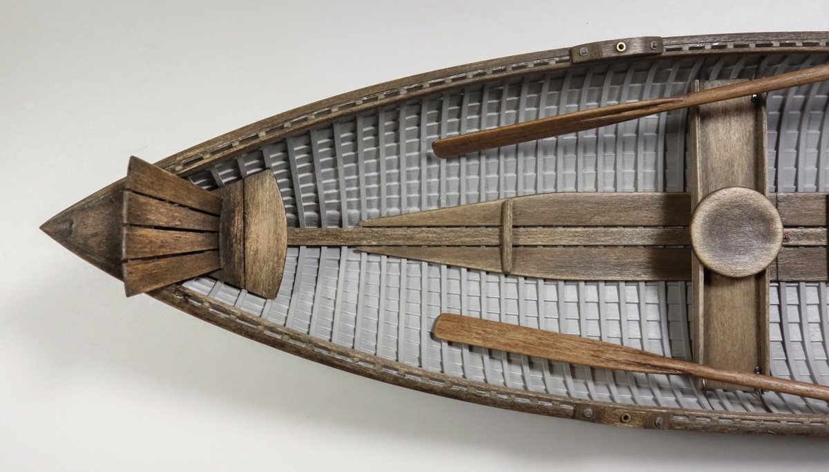
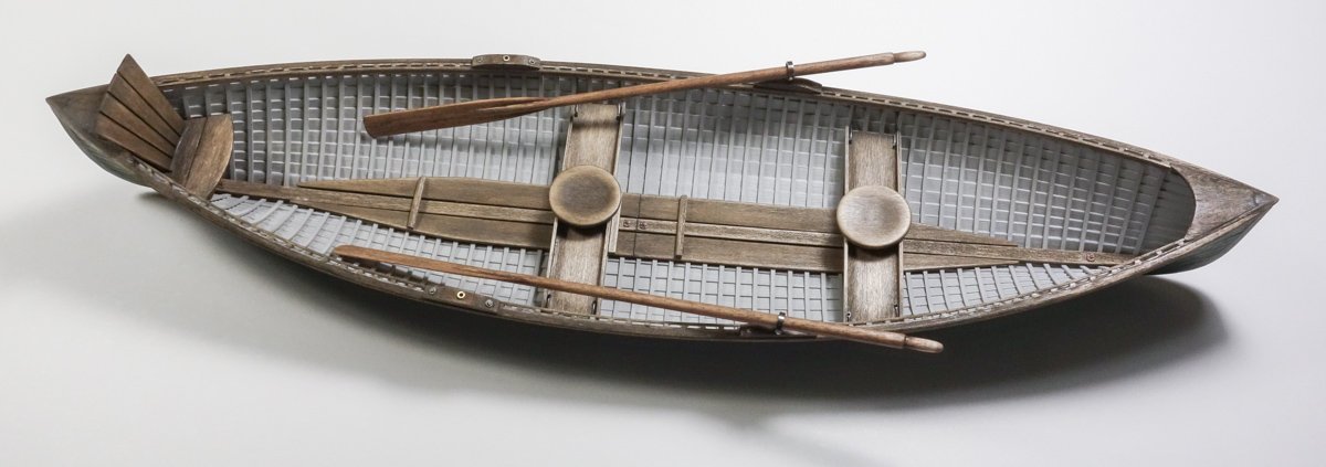
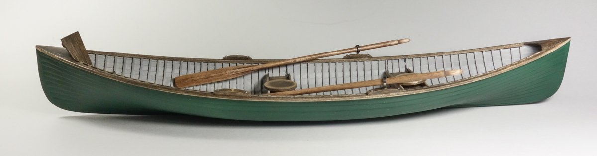
Thank you, Keith and Richard, for the nice comments. And thanks to all for looking and for the thumbs up. This update begins with the two thwarts. They were straight forward to make and mostly a file and fit affair. The fore and aft edge pieces form a tray and keeps fishing gear from sliding off. It also structurally strengthens the thwart to accept the seat. The seats are a scale 12” in diameter and slightly concave. The cutting surface grid is 1/2" To create the smooth circular depressions, I first made the holder below to chuck in my portable drill. Two layers of 1/32” basswood were laminated together with the grain positioned 90 degrees to each other and glued with PVA to the holder. A fat thumb with sandpaper creates the depression and the piece is released from the holder with alcohol. In addition to short risers which are fastened to the ribs, the thwarts are also supported by hanging rods. These rods are placed where you might normally expect to find wooden knees. Each thwart has four of these metal rods and they are made from .02” diameter phosphor bronze. They are treated with Jax Flemish Gray and each one gets a bolt head. Risers, thwarts, rods and seats are added to the boat. The staining on the decks and gunwales have been re-applied after being sanded off in the fitting process as mentioned in a previous post. They received an India ink/alcohol wash followed by a raw umber chalk/alcohol stain. It was topped with a rub down of wax which adds a degree of depth and richness to the wood and also protects the surface . In fact, all the unpainted wood on the model was treated in this same way - ink, chalk and wax. A set of oars were made from 1/8” dowel. Their lengths were determined from this formula: [(D/2 +2) divided by 7] x 25 = length, where D equals the distance between oarlocks. The oarlocks are brass - soldered together and finished with Jax Flemish Gray. They are pinned to the oars. They can be placed at any of the four sockets and positioned in any orientation. Four oarlock pads are fashioned from basswood. They are 12 scale inches long. Some stain, some bolt heads and holes for the sockets. The brass sockets are added and attached to the gunwales. Placement location of the pads varies by boat builder, but typically the socket is 12” to 14” aft of the thwart edge. These guide boats usually provided a stern seat/chair for the comfort of the paying customer. Here is the present state of the model. There is some cleanup work yet to be done on the outer hull followed by a final coat of paint, but the boat itself is close to complete. Next is a display base/stand, some assorted accessories and the final photos. Thanks for stopping by to take a look. Gary

- 79 replies
-
- 31
-
-
-
Nice update Brian. Good solution on the davit sockets - looks great. Polymer clay such as Sculpey or FIMO that will harden in a 230 degree oven in 25 minutes, is also a useful product. Gary
-
The rigging is looking wonderful Keith - as expected. Clean, neat and everything done with care and craftsmanship. Nice. Gary
-
F-86F-30 Sabre by Egilman - Kinetic - 1/32nd scale
FriedClams replied to Egilman's topic in Non-ship/categorised builds
Nice progress EG! You have some serious 3D modeling skills and I’m looking forward to seeing these components printed. Extremely interesting log, packed with information on the prototype. Good stuff. Gary -
Brig Le FAVORI 1806 by KORTES - 1:55
FriedClams replied to KORTES's topic in - Build logs for subjects built 1801 - 1850
Wonderful precise craftsmanship! Gary -
Nice work on the outbuilding OC - great combination of color and textures. Gary
-
F-86F-30 Sabre by Egilman - Kinetic - 1/32nd scale
FriedClams replied to Egilman's topic in Non-ship/categorised builds
Real nice start on this model Egilman. Very nice introduction and background info on the aircraft which is always appreciated. Will be following along. Gary -
Very nice progress OC. Gary
-
Hello Denis. Just found your comment - thanks for the visit and the nice words. I enjoyed reading about your experiences in the 60’s and the mechanic Bill up the hill from you. Sounds like he was quite a character and you just don’t find shops like that anymore - or at least very rarely. I can almost smell the place you describe. Imagine coming across a stash of model A parts today still in their original packaging. Like finding a buried treasure chest. But even so, I’m sure there are many abandoned old shops in small towns from coast to coast where walking into them would be stepping back in time. I just wish I knew where they were. Gary
-
Thank you Wefalck, Keith, Valeriy, Druxey and Ken for the nice comments! As always, I appreciate it very much. Hey Ken, no I’m not going to be able to make it to Joint Clubs this year. Have a good time at the conference and don’t forget to bring that beautiful Providence model with you! Gary
-
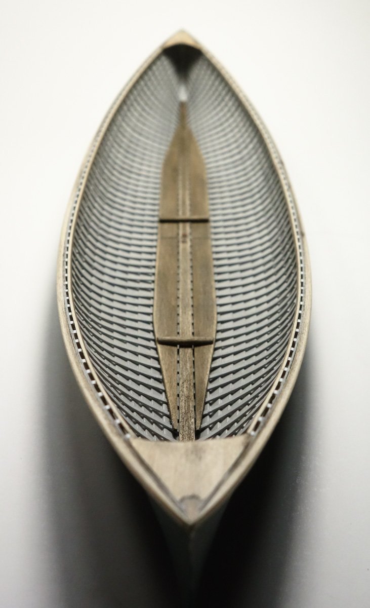
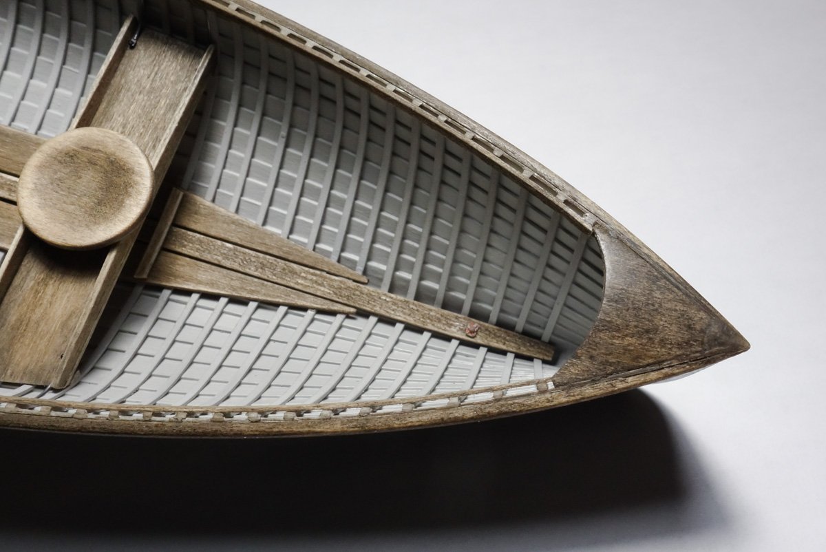
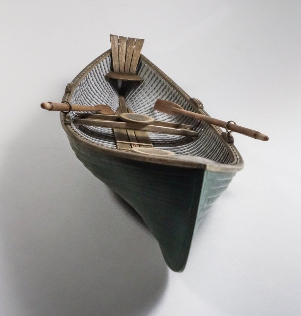
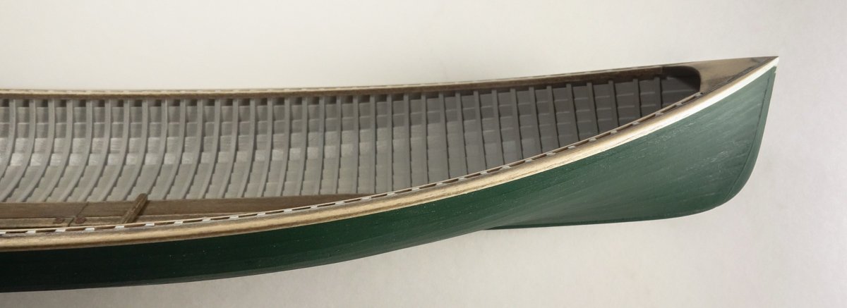
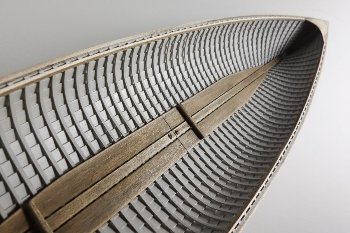
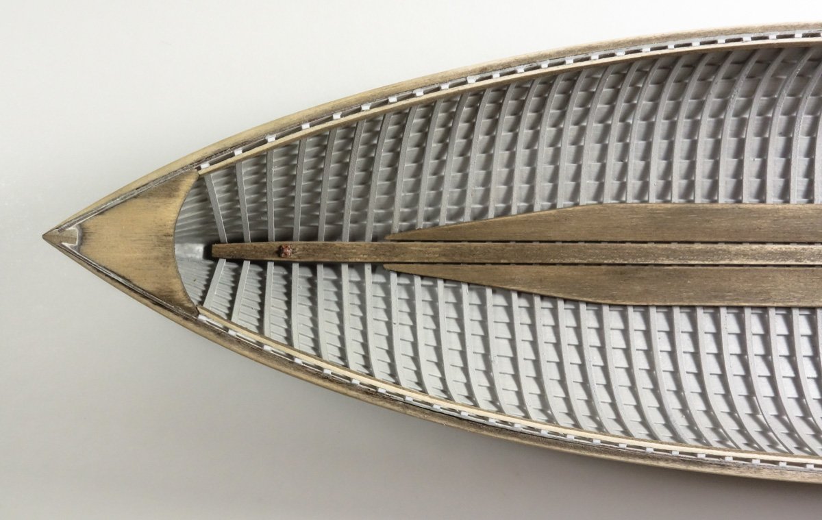
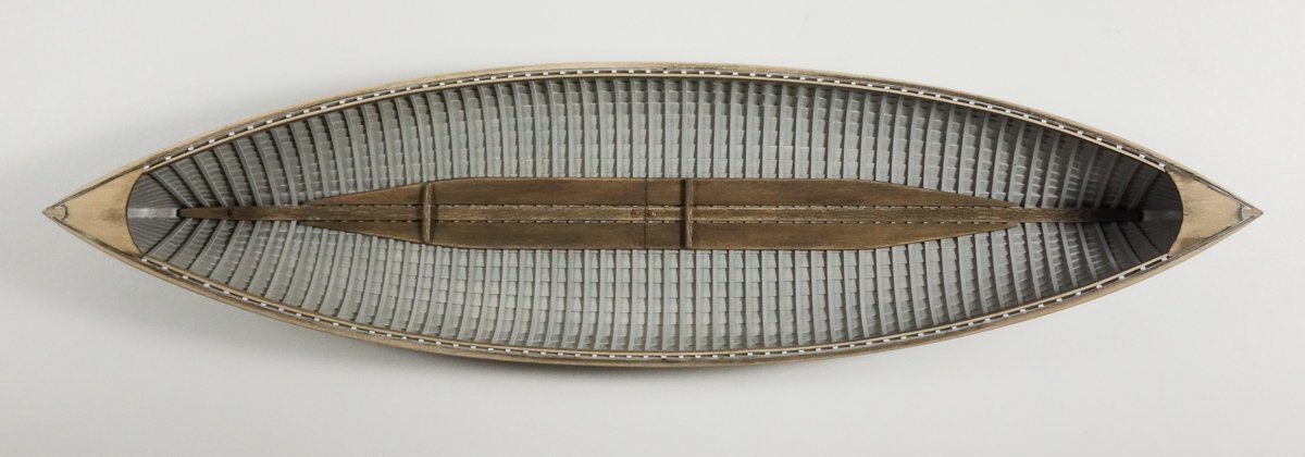
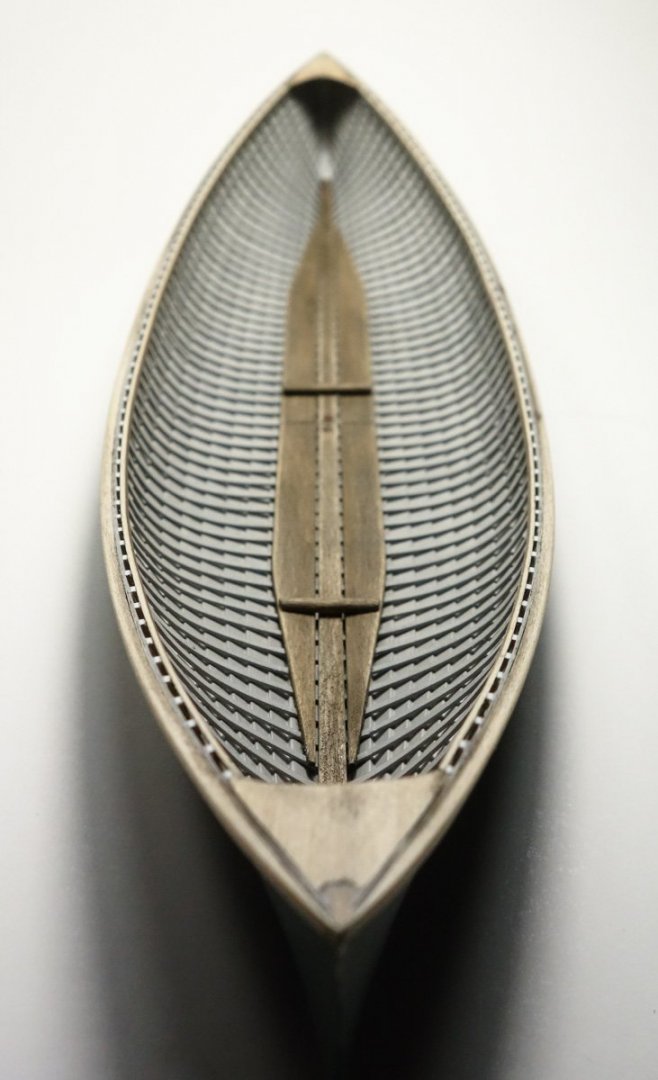
Greetings fellow modelers and thanks to all for the visits, comments and likes. I haven't spent much time at the work bench lately, but I do want to show you what I have done. The gunwales, decks and bottom boards have been placed but none are yet complete. I decided on a classic forest green for the outer hull. The model was primed and the body color is a mix of Tamiya acrylic primary colors to produce the color I had in my head. Three thin coats have been applied with at least one more to go as soon as I'm done manhandling the thing. I chose raw umber to stain the unpainted wood such as the bottom boards, etc. The stain is a chalk/alcohol mix which could just as effectively been mixed with water, but I prefer the rapid dry time of the alcohol. I pre-stained the wood before attaching the pieces, but I ended up sanding most of it off the gunwales and decks during the fitting process and it will need to be re-applied. The photo below shows the rough state of the decks and clearly there is work yet to be done. Most Rangeley boats have flat decks with straight edges to the interior, but I chose to arc the inner edge and put a slight crown into it simply because it appeals to my eye. And it adds to the canoe-on-steroids look. Hope to have more progress to show soon. Thanks for looking. Gary
- 79 replies
-
- 30
-
-
-
That’s some sweet modeling Tom - the stove looks real! Gary
-
Oh, I do like that brass wire scroll work Richard - very nice. Gary
-
It’s great reading your posts again Michael - welcome back. Nice progress on the frames. A few years ago during a particularly heavy snowfall winter, we had a porcupine take up residence under our kitchen deck. My wife and I named him/her - you guessed it - Spiny Norman. What a cultural impact the Pythons have had on our generation. Looking forward to your future posts. Gary