HOLIDAY DONATION DRIVE - SUPPORT MSW - DO YOUR PART TO KEEP THIS GREAT FORUM GOING! (Only 20 donations so far - C'mon guys!)
×


FriedClams
-
Posts
1,368 -
Joined
-
Last visited
Content Type
Profiles
Forums
Gallery
Events
Everything posted by FriedClams
-
 Excellent modeling Valeriy. As always, such a pleasure to follow along. Best wishes. Gary
 -
Wonderfully precise work John, and so small. The Constitution watch case model is extraordinary. Gary
-
Good research OC. - that Vallejo looks spot on to me. Gary
-
Excellent fitting of those planks Keith. It's going to look great all finished and shiny. Mahogany? What has worked for me before, is a liberal rubbing on of bee's wax to the removable piece. Gary
-
Thanks Keith. Yes, it is a pity about the rivets, but perhaps some rainy Sunday, I'll put them on - or not. Hello Keith. The extreme light angle really makes them pop out for sure. Very nice Farmall tractor you have there. What year is it and did you do the restoration yourself? Do you show it off at county fairs and such? A family story with it? OK, I'm done asking questions. Thanks for the nice words on the boat Keith. Thank you so much Ken, I appreciate it. Hi Mike. If I find any glue globs, I'll do as I always do and cover them up with something - a coil of rope maybe. Once a model is done, I don't point viewers to its short comings if they haven't already found it on their own. Thanks for the nice comment Mike. Thanks Wefalck. Using styrene does solve many problems such as crispness in the final look and material flexibility. All period boats were painted, so with that decision made for me, choosing styrene for these thin ribs was easy. I will give your diamond burr suggestion for the tires a try. The material is quite soft and has a tendency to tear rather than cut. LZ Models in Ireland produces a set of resin wheels as an upgrade for the kit but after shipping to North America, it costs almost as much as the kit itself. Thanks to all for the likes and for taking a look. Gary
-
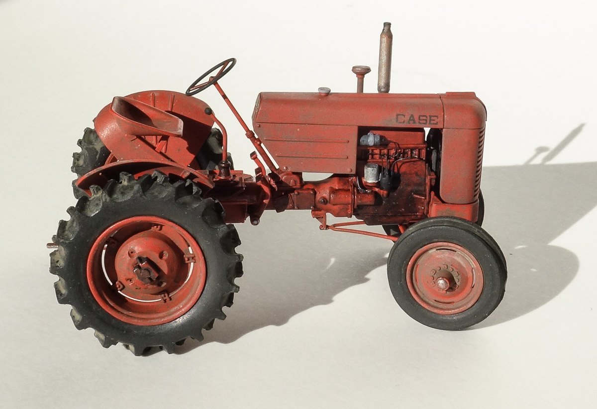
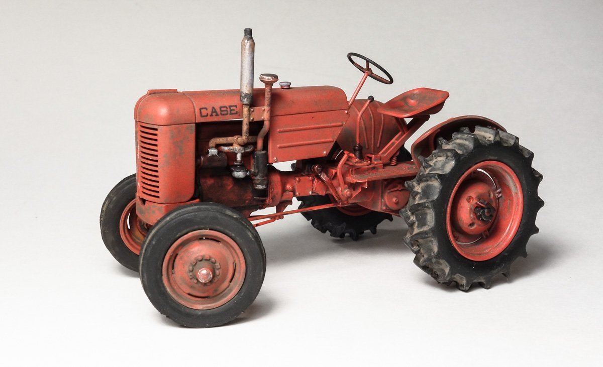
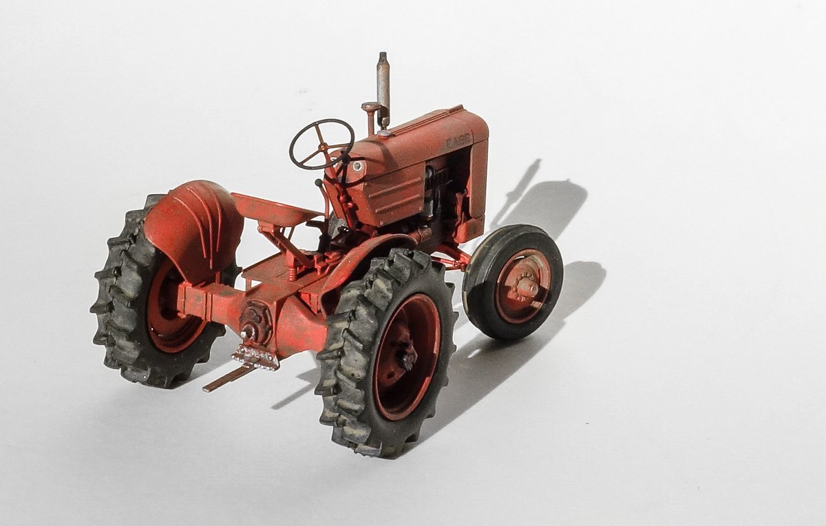
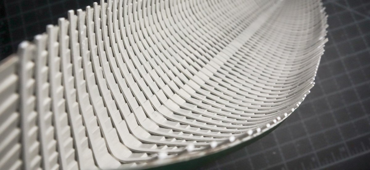
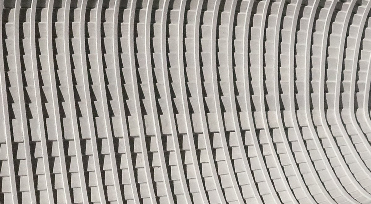
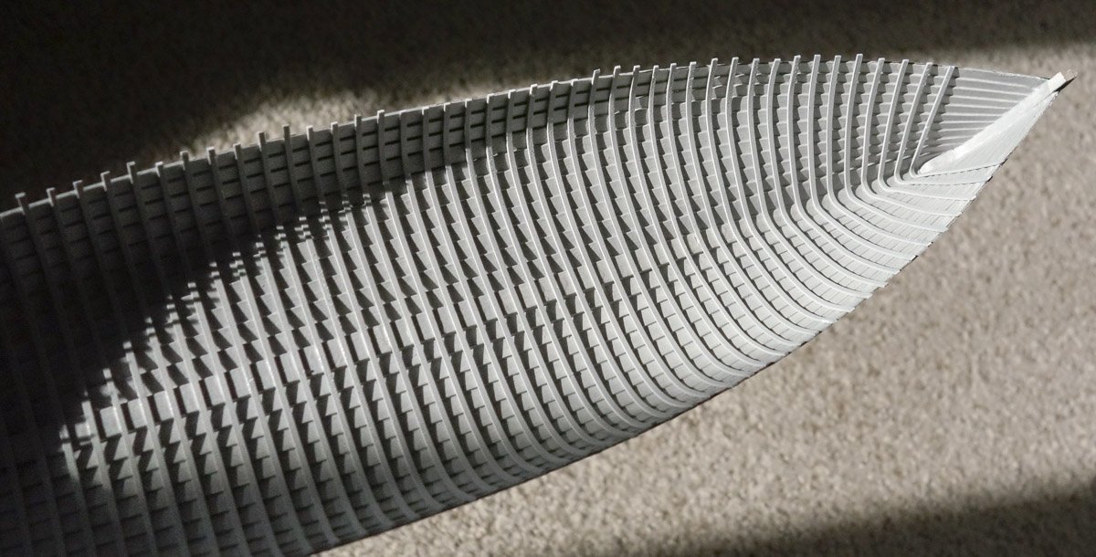
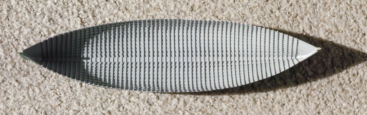
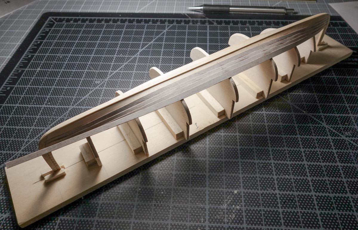
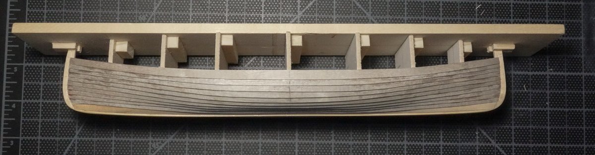
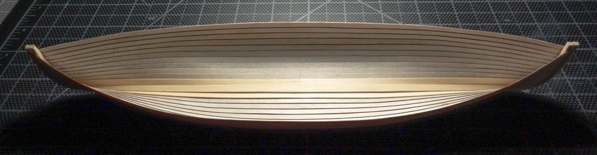
Greetings fellow modelers I have a short progress report on the Rangeley boat, but first I'd like to share a recently completed plastic model. I thought you might be interested in this, because if you're like me, sometimes it's refreshing to work on a project that is outside your usual modeling interest and medium. Typically, I work on one model at a time, but to break out of a modeling malaise, a small model like this which is inexpensive and can be completed in a few days, is just the ticket. Case VAI 1942 – 1955 by Thunder Model 1:35 It's marketed toward military modelers and typically sells around $25 U.S. or less. At around 70 parts, it goes together quickly and easily with only a few fiddly spots. It took more time to paint than build. All I added was ignition wiring and I modified the steering linkage to cock the front wheels. It's about 3.5” (9 CM) in length – and who doesn't like a little red tractor? A minor complaint of the kit is the silicone tires have seam flash that is difficult to remove. Back to the Rangeley. The ribs have been installed and I began by brush painting the interior of the hull gray. I added a little orange into the mix to remove some of that chalky look and to warm it up a bit. Normally, I would not paint first and then glue pieces to it, because it isn't secure, and the part will pop off at the slightest excuse and take the paint with it. But this boat has many ribs (61), and they are placed closely together which would make painting the hull after they are installed difficult, even with an airbrush. I was concerned about too little paint getting under the ribs and/or pooling in other places as a result of trying to get full coverage. And once the bottom board and the gunwales are installed, the ribs will be secure and won't be going anywhere. The ribs are styrene strip .023” (.56mm) x .043” (1.1mm) and in 1:18 they are a very close match to the full size 11/16” (17.5mm) x 3/8” (9.5mm) material. They were airbrushed on three sides with the same gray. The ribs were placed with the help of a few simple made tools. The first was a square made of heavy paper. This showed me when the ribs were out of square across the breadth of the hull. A squared stand with hanging tabs, helped in checking rib plumb. This worked well at the center portion of the hull but became quite useless as I advanced closer to the stems. And a little spacer to assist in placing the next rib. Again, this also worked great until I approached the stems at which time the working area became too tight and too steep. In the photo above, you can see I wasn't terribly concerned about slopping on the CA at the keel, because the entire length the keel will be covered with bottom boards. The same is true at the top of the shear as it will be hidden by the gunwale, although I did apply the glue at this location with greater care. But the length between those two points, where the ribs lay across the laps, I wanted to look as pristine as I could make it. A big shiny glob of glue there is unacceptable. It did not turn out pristine, but it turned out to my satisfaction. The process in attaching each rib went like this. With the spacer in place, the center of the rib was glued down hard with CA to the keel. Then the underside of one of the free ends was wiped with a swab wet with PVA and then pushed down to the hull while at the same time pushing against the spacer. Repeat on the other free end. After the PVA dried, the ends of the ribs were reinforced with CA at the shear where the gunwale will be placed. Easy, but monotonous in the extreme. As is true of most things like this, you develop a workflow and fall into a rhythm as you proceed that improves the quality and speed of the work. Unfortunately, that only happened as the last rib went on. Defeated by creep, only 58 of the 61 ribs made it onto the boat. But who's counting. Thanks for stopping to take a look. Gary
- 79 replies
-
- 29
-

-

-
Nice progress on this F15 Dan. I like your foil imprint off the handle knurl - very resourceful. Spring equinox yes, but it looks a bit chilly still? Gary
-
Congratulations Ken on finishing your beautiful model! It is truly a wonderful piece of work. I have always been drawn to the contrasting tones of wood that you used and how crisply everything is made. Very nice. Giving any hints about your next project? Gary
- 238 replies
-
- 2
-
-
- sloop
- providence
- (and 1 more)
-
Nice tutorial on the base Wefalck. That will go in my note folder in case I ever decide to try it myself. Very nice result. Gary
-
Great progress and beautifully done OC. Nice upgrade set too! Gary
-
Hello FF and thanks for stopping by. It's a good question, but no, the ribs will be simply glued into place. I decided not to include rivets because the numbers are too great. There are 22 strakes and 61 ribs, so that would require 1,342 rivets. Add to that the plank-to-plank rivets at the laps between the ribs and that brings the number to 2,700. And there's yet more lap rivets from the last ribs to the stems. I'm not that dedicated – not on an 11-inch model anyway. Thank you Valeriy for the kind words. It is so good to hear from you and I do hope that you and your family are well and safe from the madness. Gary
-
Nice proof of technique EG! I used to work for a beverage can manufacturer, and we would go through miles of coiled aluminum stock every day. The material has a visible grain and it refracts light in a way that's hard to describe and differs depending on light angle. Sometime glaringly bright and other times soft and milky like a dirty old mirror. It looks like this technique captures that. Gary
-
Looking very nice Keith. That's a shame because I think the flags look great, especially Old Glory. Nice subtle wave in it - I can almost hear it popping in the wind. But if something doesn't seem right, it'll always bug you. Gary
-
Ouch ! I dropped a model I spent much time on once, but it miraculously landed on its keel with little damage, but I still cussed at myself for a week. Will be watching for the repair and new progress. Gary
- 30 replies
-
- 2
-
-

-
- small
- clinker built
- (and 2 more)
-
I too like the R&B finish EG. Much more authentic looking than straight up silver paint. Good save on the landing gear too. Gary
-
Thanks to everyone for the visits and the likes! Hey Keith. I went to the Midwest website to order their 1/64 plywood and I found they don't even list it. And they don't list their 1/32 or 1/16 ply either, but they do offer all the thicker sizes. I wonder if they are phasing out the thinner materials. On-line retailers are asking a pretty penny for the 1/64 ply – $30 to $48 for the 12” x 24” sheet. I bought mine at Menards for $17 – extremely reasonable shipping too. And thank you for the nice words Keith. Hello Wefalck and thanks. I filed opposite bevels on the edges of the two planks where they overlap. I tapered the length of the bevel for about 10mm in attempts to feather it into the stem, but I'm not happy with it as it presently sits. They need further attention. I too am surprised Druxey, and I half expected it to close up like a clam shell when I pulled it from the form. Delicate yet strong, like an eggshell. Thank you for stopping and for the nice comment. Keith, I've been following your Germania build from the beginning and I haven't seen anything that's close to a “suck it and see” approach. You are one of my precision modeling and technique heroes. And thank you for the kind words. Thanks Ken. Sometimes I get to typing-out-loud and don't know when to stop. Gary
-
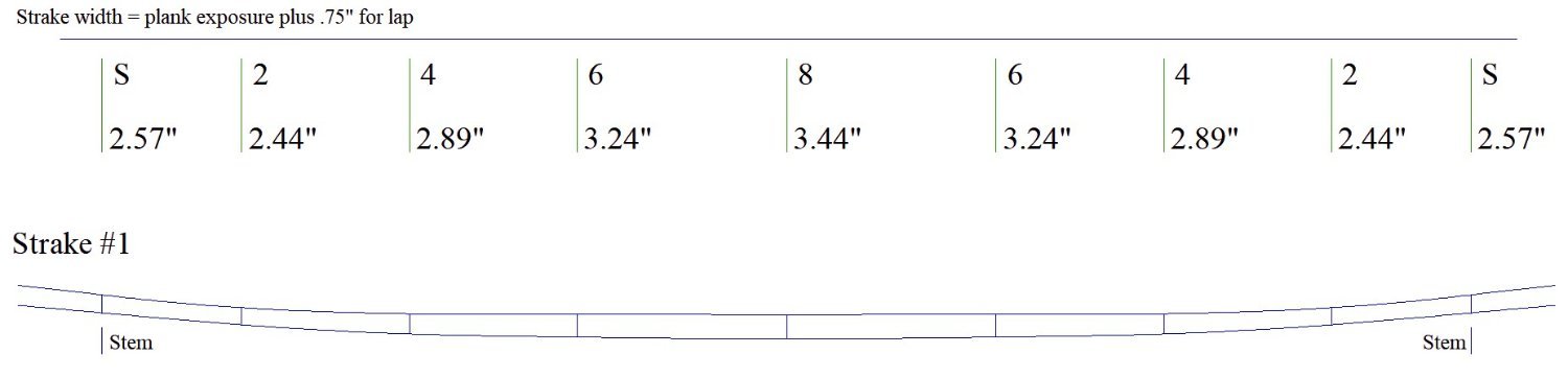
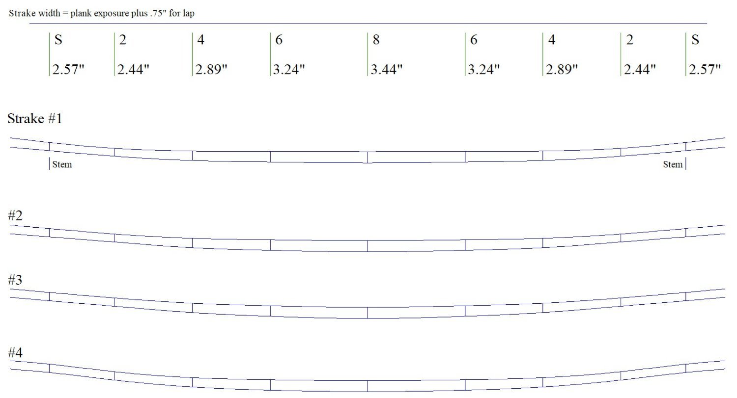
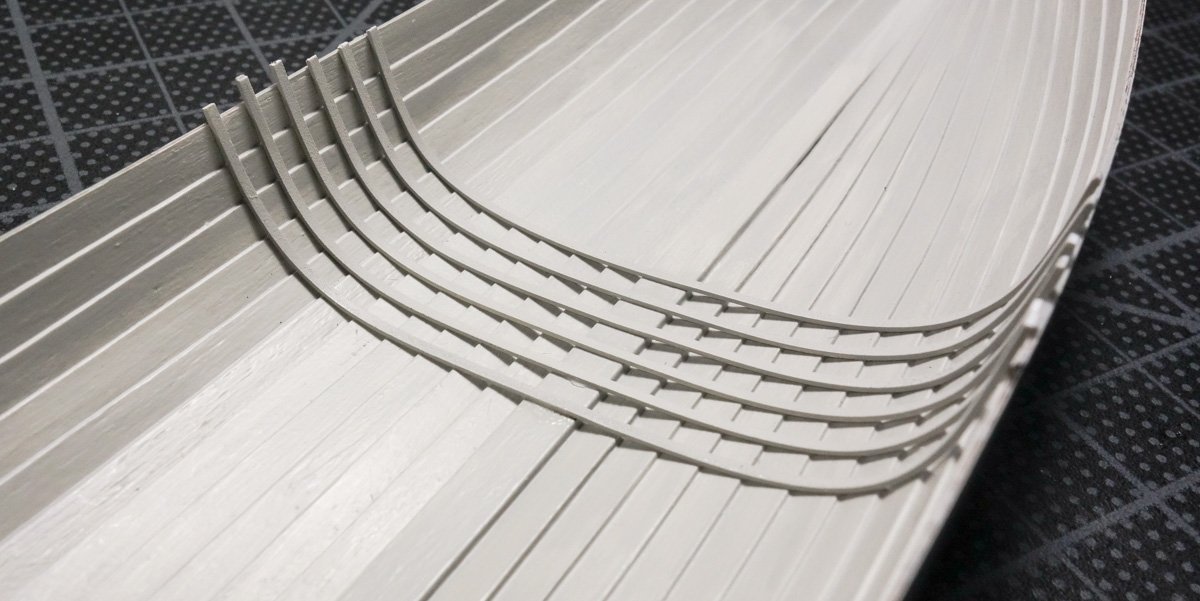
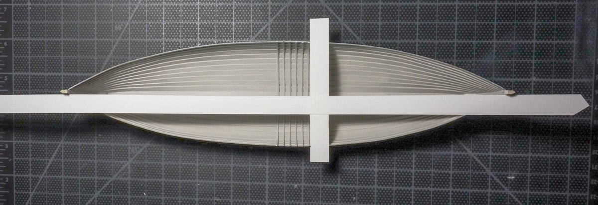
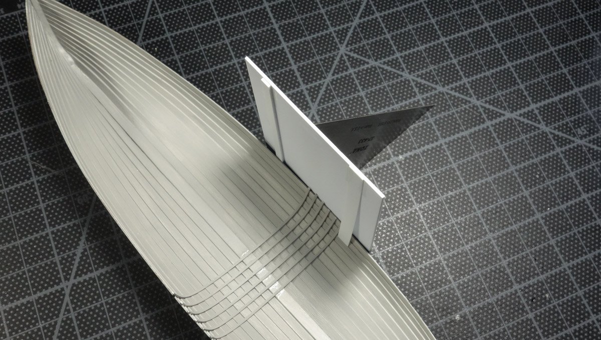
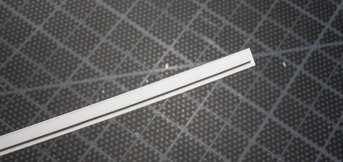
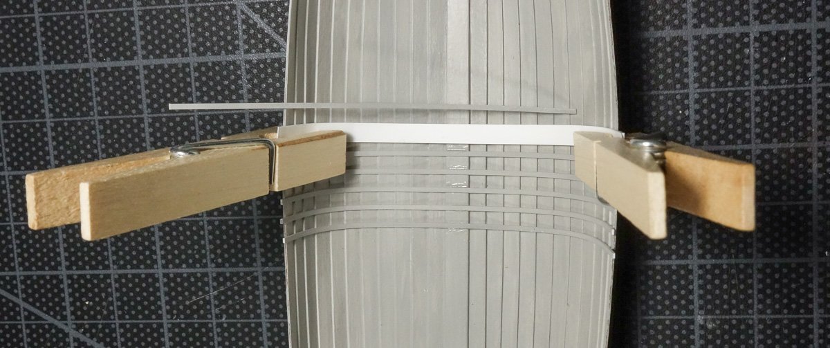
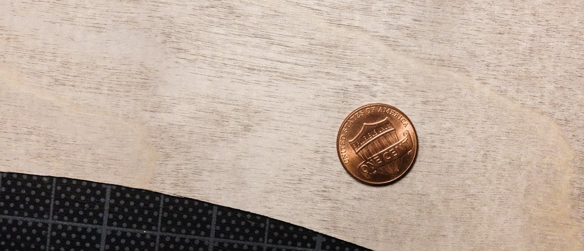
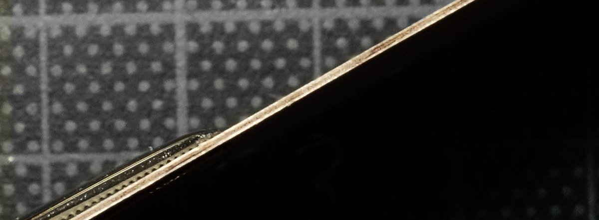
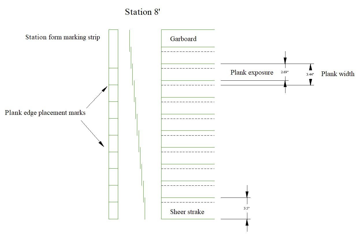
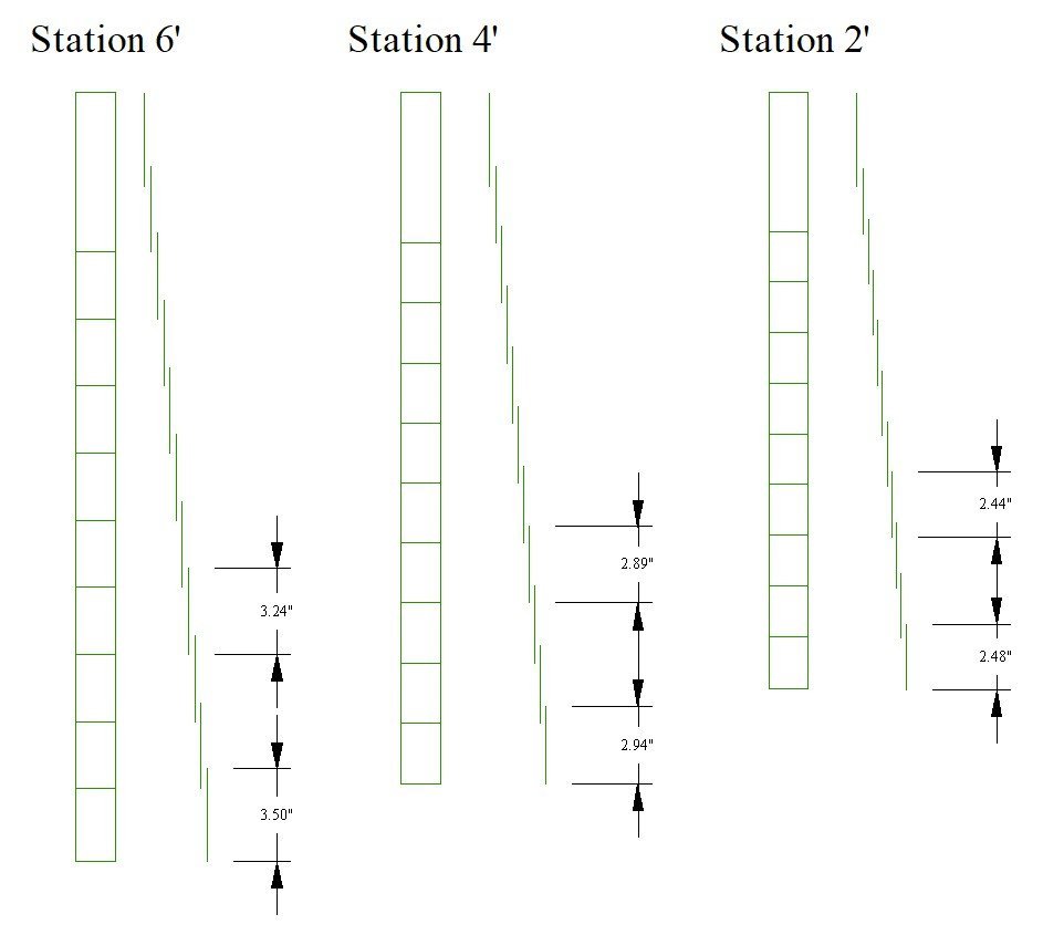
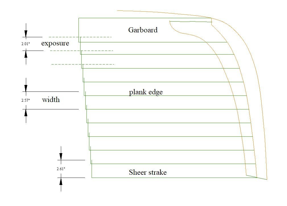
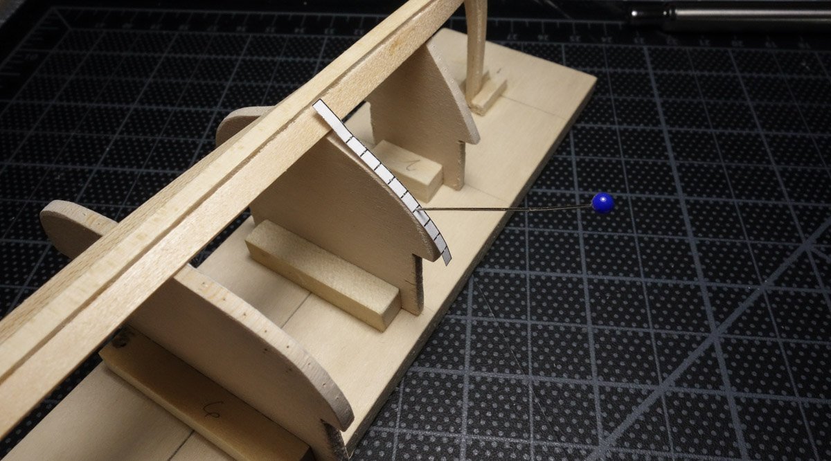
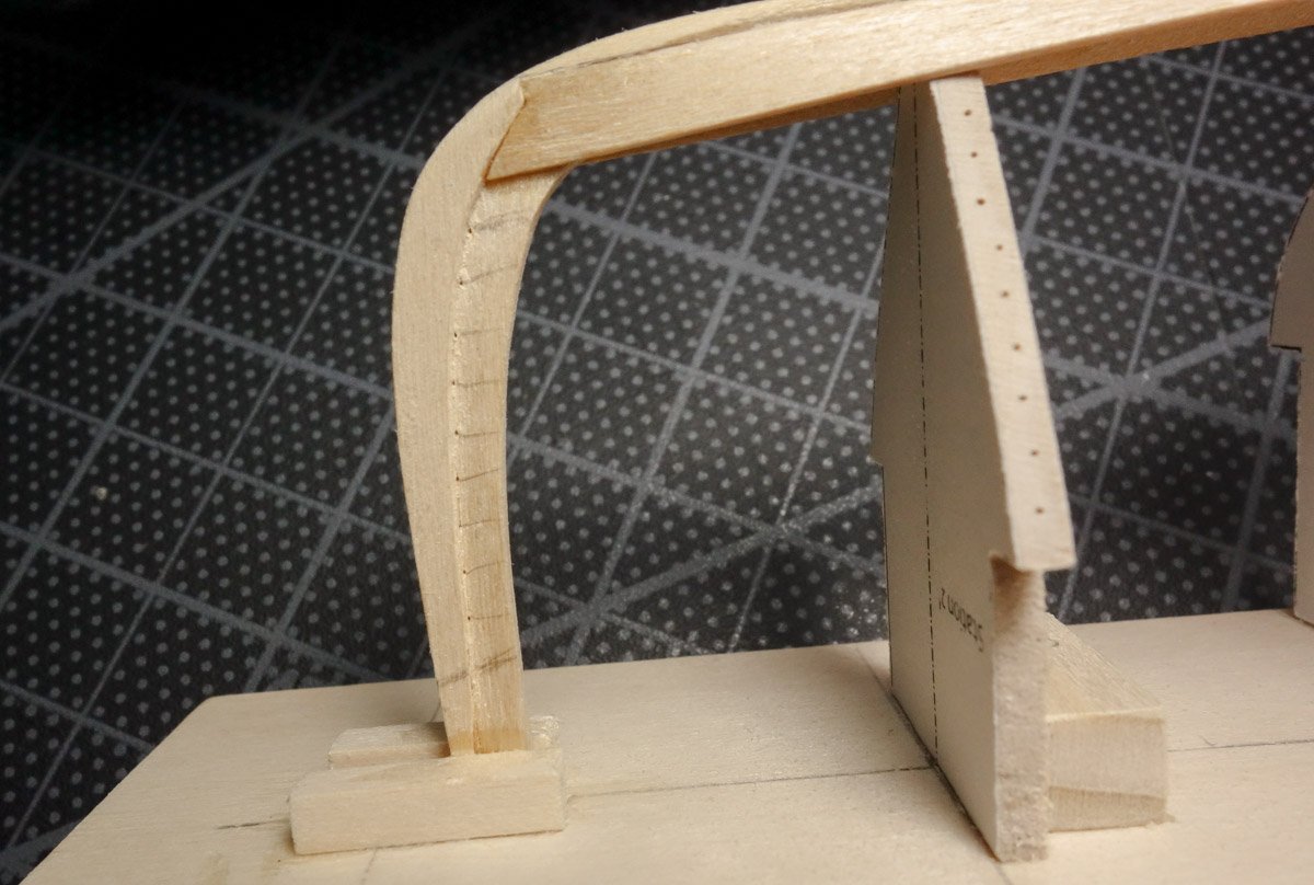
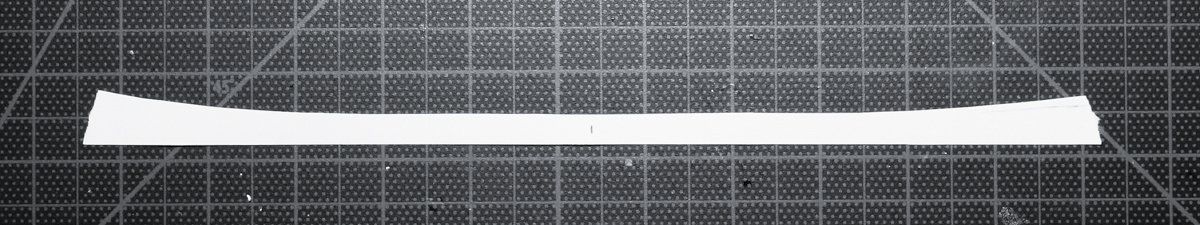
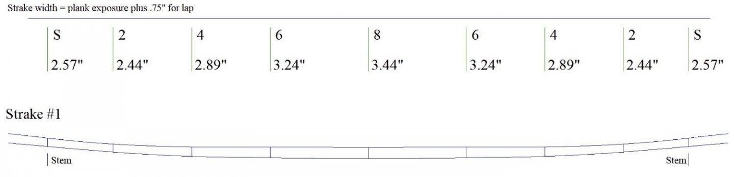
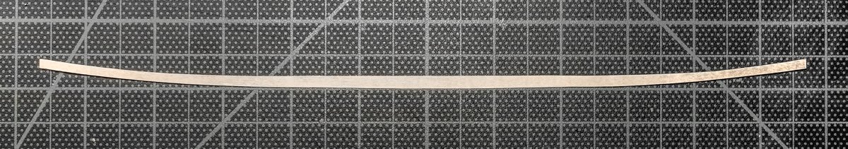
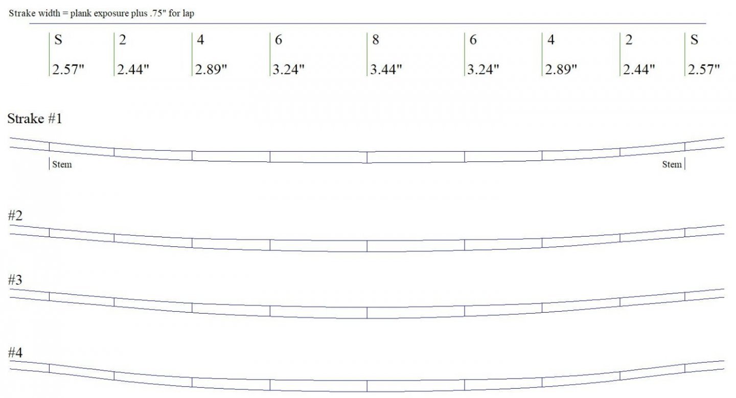
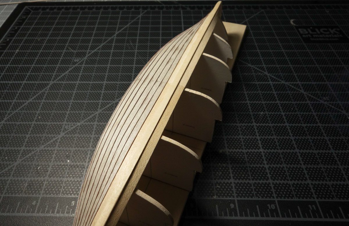
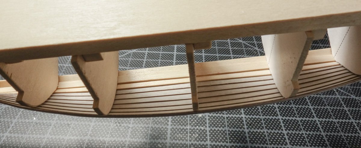
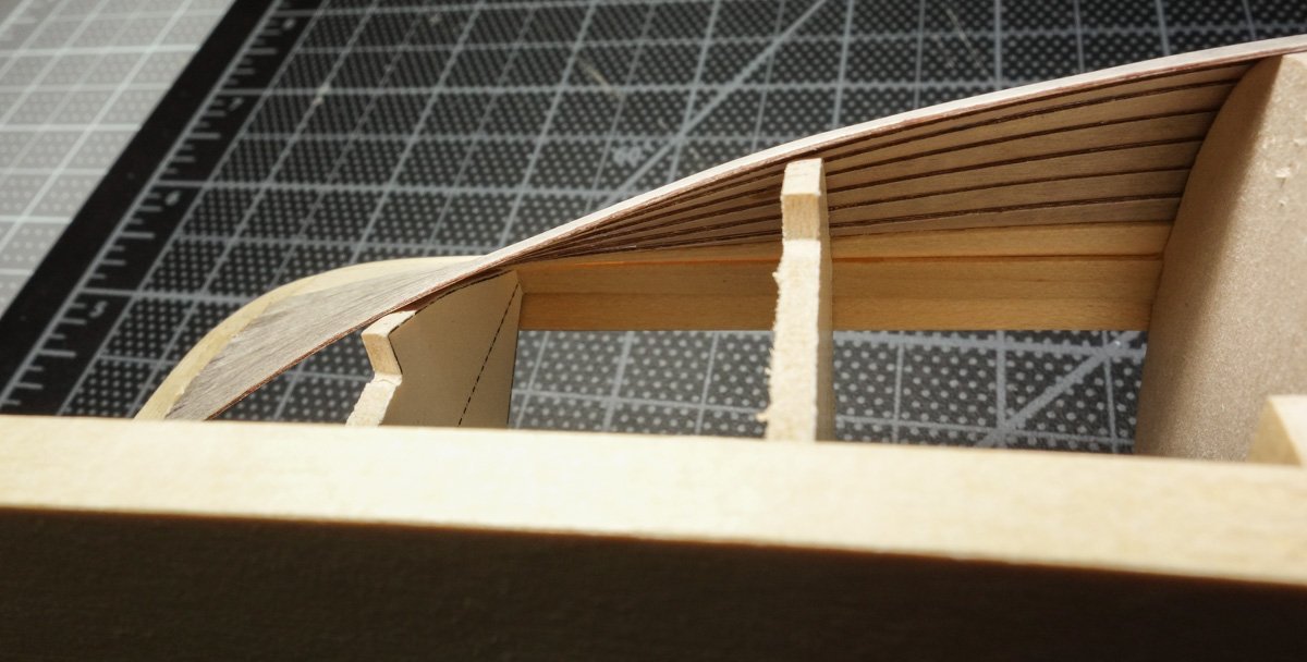
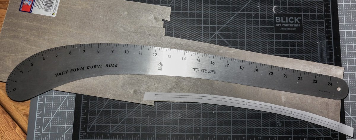
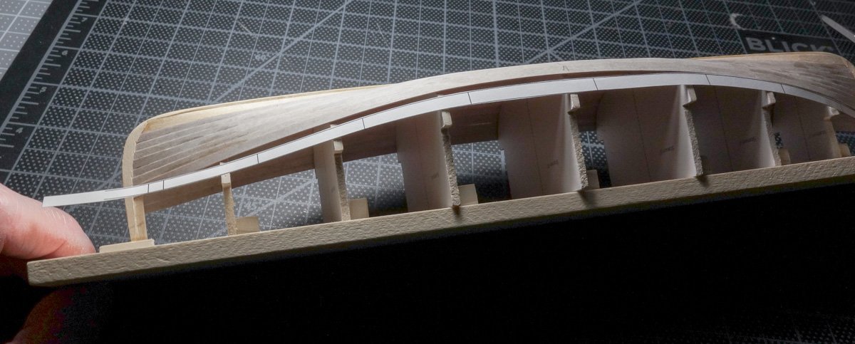
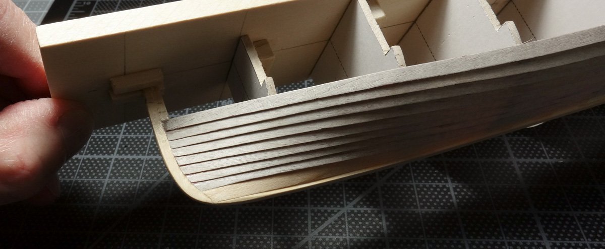
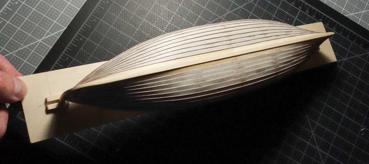
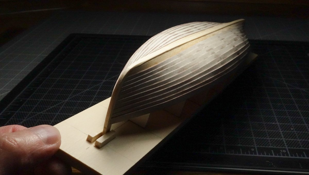
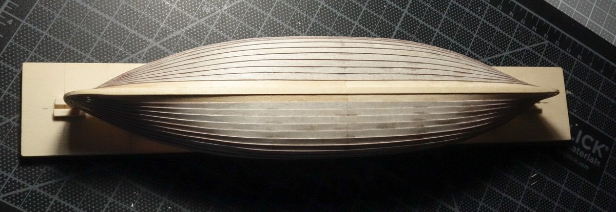
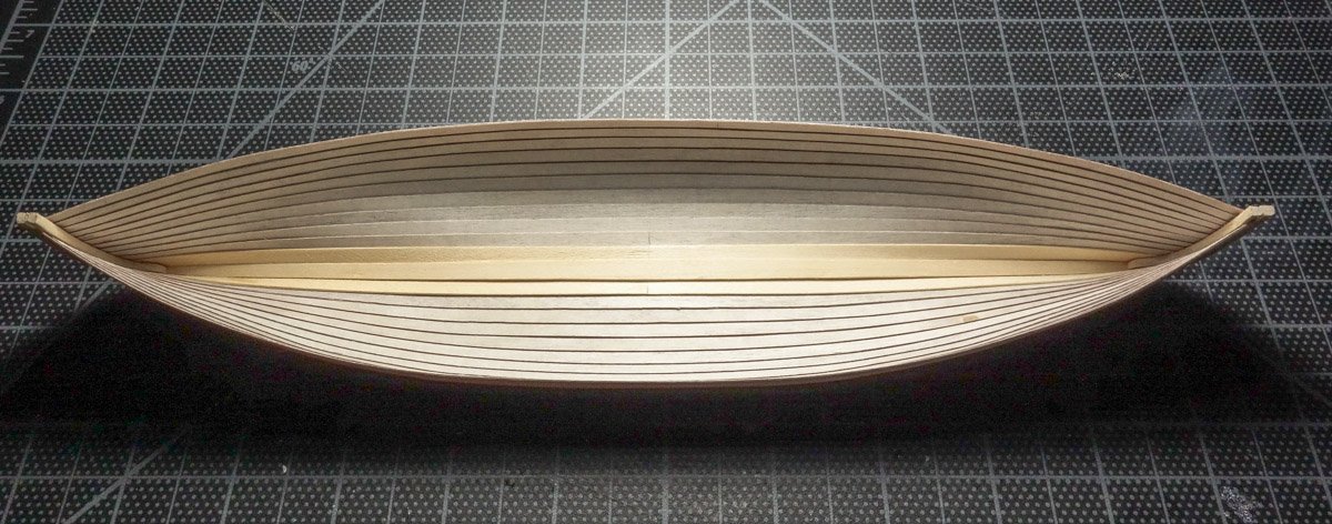
Thanks to all for the likes and the fine comments – it is appreciated. Moving on to the planking, I first decided on a material to make them from. The 1:1 boat has a plank thickness of 5/16” (8mm) which equates to .0173” (.43mm) in 1:18. I wanted a material that was stiff and would return to its natural flatness after bending or being racked – and no kinking or denting. So I decided to use 1/64” (.0156) birch plywood. This 3-layer plywood is considerably thinner than most single layer veneer and much tougher as well. It's manufactured by Midwest Products and is available in 12” x 24” sheets. Edge view of the plywood showing the 3 layers. Each layer is about .0052” (.132mm) thick – they must have some very sharp tooling. After I built the hull form, I checked the station fairness with battens, but I didn't sand/fair any of the forms like I would if I were gluing planks to bulkheads carvel fashion. In fact, I slightly back beveled all the stations so the planking rests against a narrow edge at each form. I hung each strake as a single plank from stem-to-stem, and due to the stiff springy nature of the plywood, they produced a nice smooth arc over the forms. Another advantage of this material is that the 90 degree inner layer kept my cutting knife from being pulled off course by the grain pattern, even when cutting closely with the direction of the grain. But there are also some disadvantages and I think the biggest is that it doesn't take much surface sanding to wear through the outer layer and reveal the darker inner layer. Also, the adhesive holding the sandwich together is apparently abrasive because it ate through knife blades like they were Spanish peanuts. Admittedly, these were cheap junk knock-offs pretending to be knife blades, but just the same I kept my Bard-Parker blades at a safe distance. There are 11 strakes per side and the garboard, which is wider than the others, is already laid down. The shear strake is also wider to provide a consistent plank exposure after the gunwale is attached. The remaining 9 strakes are equal in width and that width was determined by dividing the remaining distance between the garboard and shear strake at each station. These distances were taken from the CAD drawings and not by measuring the forms themselves, because I don't care what the form measurements are, I only care what the drawings tell me the strake widths should be. The station forms are needed to provide the shape of the hull, but I don't reference them “as built” because they are only temporary. And even though they should be in agreement, I let the drawings determine where the plank edges are, not the forms. So, I work up a plan and a tick strip for marking the forms per the drawings at station 8' – the center of the boat. And the same for the other stations. These are the total plank widths with a .75” lap already added. And the stems. The tick strips are printed out and used to mark both sides of the station forms. They are positioned and a pin is pushed through one of the plank edge locations. The pin is not removed until all the other locations are pin punched. Same thing on the stems. The pencil marks are there to help me find the pin holes. The way in which I determined the shape of each strake is the work of a barbarian and is not offered as an alternative to doing it correctly. There are some great articles on spiling and planking in the NRG database and they are a good read if you haven't already. The first strake is spiled off the garboard in a traditional manner by placing heavy paper in close proximity and tracing a parallel line with a pair of dividers off the edge of the garboard. After cutting out and test fitting, the curved paper is photographed. The photo is imported into CAD, scaled, traced and becomes the upper edge of the #1 strake shown below. The strake widths (including the .75” lap) for all 9 strakes at each station are assigned and added below the line. A spline curve is then used to connect the points and create the arc of the lower edge of the strake. I am referring to the upper and lower edges of the strake as I look at the boat upside down. Also, I have left extra length beyond the marked stem locations. This strake is printed on copy paper, cutout and test fit. No adjustments were needed, so it was then printed on adhesive backed full sheet label paper and stuck to the plywood and the strake was cut free. The adhesive paper is peeled off and the strake is sanded. The shape of the next three strakes are all determined in CAD. The bottom edge of strake #1 now becomes the top edge of strake #2 and so on. Again, the widths at each station are added and the points connected by a spline curve. Each new strake is now slightly more curved than the one before it due to the widths being greater at the center than at the ends. The process continued with no adjustments for the first three strakes and only a minor correction for the fourth strake. I should mention that only one half of each strake was created with the other half simply being a mirror image. Each plank is glued to the previous one starting at the center and working outward to the hood ends. They are attached by lining the lower edge to the pin holes created with the tick strips and then a tiny amount of CA is applied at the lap, allowing capillary action to pull it into the joint. This was done at each station and various points between like it was spot-welded. After each plank was placed, a flat bevel was filed to the lower edge creating a lap landing spot. In the real world, both planks would of course be beveled at the lap, but not here. It's always been my intention to paint the boat, simply because all the period boats were painted. It makes good sense for working boats to have a sacrificial layer that is easily renewed. And I don't need to worry about the glue stains. I've been able to get away with creating strakes this way because I've been working in an almost 2-D world. The first four strakes sit nearly flat side-by-side on the same plane and only the ends are folded back. But now, as I begin to round the belly of the hull, the geometry changes. The lower curved edge of the previous strake still matches the upper curved edge of the new one but the face of the strakes are now pointing in different directions. With the free lunch over, I spiled off the #4 strake with dividers and paper to gain the proper curvature for the #5 strake and continued in CAD as before. I was able to create #6 and #7 strakes in CAD by applying the same percent of change in their arcs as in the #5 strake because they share the common radius of the hull. These three strakes around the belly of the boat were the most challenging and I resorted to edge bending. Now hold on, it's not what you think! Because the strakes are not attached to anything except each other, I had a difficult time keeping them against the forms as I rounded the curve, especially at the center. By reducing the curvature of these three strakes, the edge bending pulled the outer lower edge of the planks inward towards the form. Not a perfect solution, but it worked. I continued my way down to the shear strake. In the end, I spiled four of the strakes and adjusted all but three of the others. The amount of time I spent in CAD probably exceeded the time it would have taken to spile each one right off. But the payoff was that I simply printed and cut the planks for the opposite side of the boat without adjustments or even having to think about it. I used one of these, so my planks didn't come out looking like an old french fry. A couple of in-process photos. Exaggerated lighting to accentuate the strake lines. The form was removed without drama, although I did have to break one of the 2' station forms out. And a little PVA on the inner keel was removed with alcohol. Sorry about the wordy explanations and thanks for stopping by. Gary
- 79 replies
-
- 29
-
-
-
As others have stated, excellent work on the life rings and associated details. Your posts are always a pleasure to read. The launch promises to be a build within a build - looking forward to it. Gary
-
So good to see you posting again Richard, sometimes it's good to take a break. Nice progress and such clean work on the cabin. I especially like the curved wall and moldings. Nice work area too! Gary
-
Your detailing work is wonderful and inspirational Marc. Very, very nice! Gary
- 2,696 replies
-
- 4
-
-
- heller
- soleil royal
- (and 9 more)
-
Nice work on this Abrams OC. Miss reading your posts on the Waterloo diorama - just taking a break from it? Gary
-
Excellent Jean-Paul - she's looking very smart. Gary
-
Thanks for your vote of confidence Tom, but I'm far from an expert and my weathering is always a trial-and-error sort of thing. When something doesn't work, I try something else. I'm glad you've decided to take the plunge and you're first attempt looks good from what is visible in the photos. I think it's a fun process and as you gain experience, you'll develop confidence and a feel for it. I've learned most of my methods from other modelers and there are many great modelers out there who will share what they know. Be sure to check out YouTube on the many inventive ways folks add realism, age and wear to their models. Since you're new to weathering, I thought I'd I share a few things I've learned over time. Reference material is so important to see where and how an object wears or how it decays. I always considered myself an observant person until I started in with this weathering thing. But I've found that the mind's eye sees things differently than the way an object looks in reality. There is nothing that will improve your skills more than studying images of the real thing or similar objects. They will point you in the direction you need to go. It's important to know the properties of the media and tools you're using. I've been using Bragdon powders for years, so I know what to expect from them, and more importantly, I know their limitations. Same is true for oils, chalks, acrylics, washes, etc. Picking the right medium for the results you're looking to achieve is critical. I always test what I'm going to try on a piece of scrap first using the same materials and paints that I intend to use on the model. Every material and finish accepts washes, pigments, etc. in a different way and what worked great in one instance may be a total bust on something else. I can't tell you how many times I've saved myself from ruining a decent piece of modeling by testing it out first. And finally, in my opinion, subtlety is the key to success and it's something I have to work harder at. It's easy to get carried away and difficult to turn back. You can always add on more later, perhaps the next day after you've had a fresh look at it. More often than not, when I “weather” I'm really just looking to suggest wear, usage or age, and it typically takes very little to get there. Good luck on your weathering journey. You're an excellent modeler and you'll do well. Gary
-
Beautiful work once again Brian! I remember seeing a modeler use a Cricut cutter for the repetitive ornate detail work on scale brick buildings - corbel detailing and the like. Looks like a fun tool to experiment with. Your model is looking very nice indeed. Gary
-
That’s a nice looking result Egilman! Looking forward to seeing it applied to a larger area. Gary