HOLIDAY DONATION DRIVE - SUPPORT MSW - DO YOUR PART TO KEEP THIS GREAT FORUM GOING! (Only 20 donations so far - C'mon guys!)
×


FriedClams
-
Posts
1,368 -
Joined
-
Last visited
Content Type
Profiles
Forums
Gallery
Events
Everything posted by FriedClams
-
 What a fun and interesting project you have going on here, Tom. I’m going to have to check out your other ship component threads as well. Very nice exacting work. Gary
 -
Excellent Ken! One would never guess that those anchors are carved from wood - they look like iron. Gary
- 238 replies
-
- 3
-

-
- sloop
- providence
- (and 1 more)
-
Thanks for walking us through the testing and trials on the simulated bare metal finish Egilman. You've done your due diligence and I appreciate your sharing the formula with us. I look forward to seeing it applied to a model. Wise choice to test it out on the sacrificial P-51 - because you just never know what can happen. Gary
-
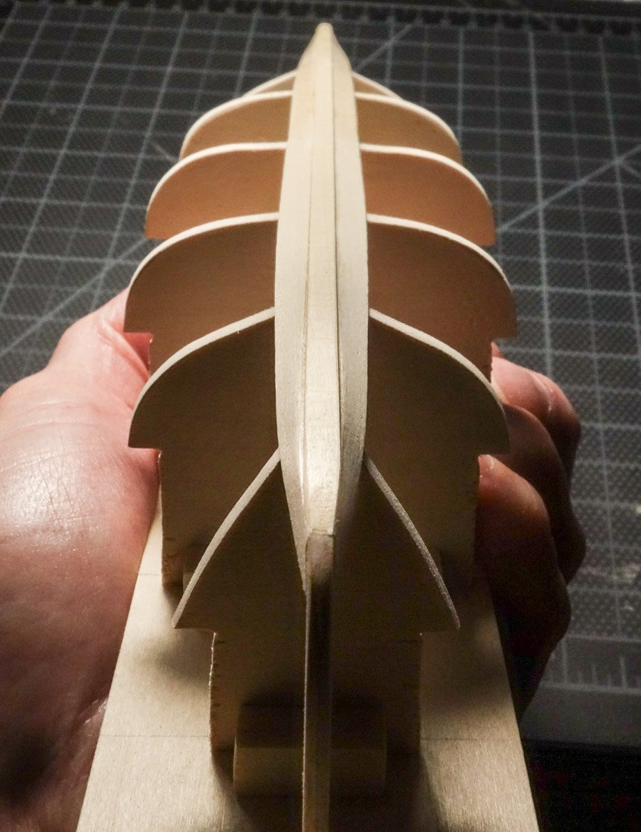
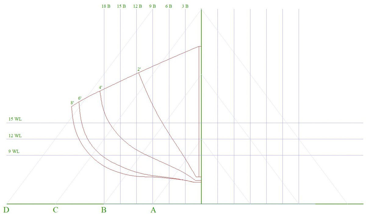
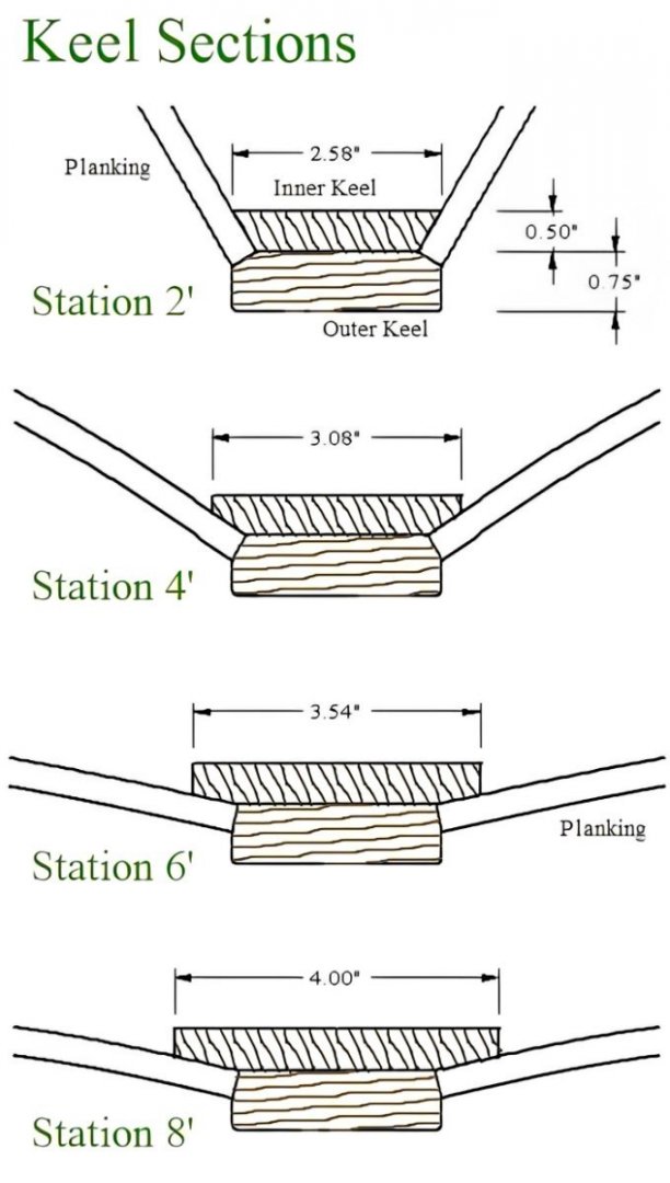
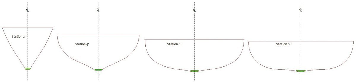
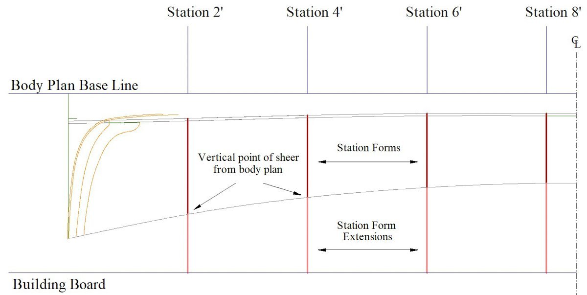
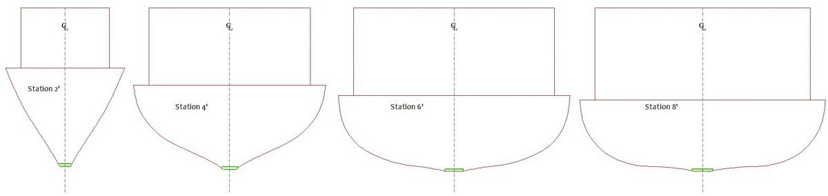
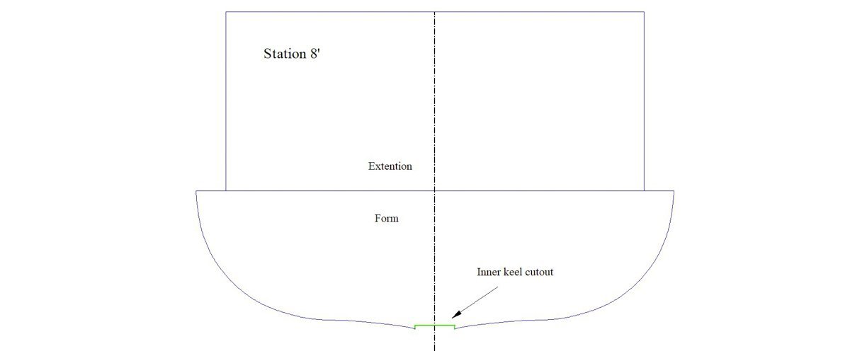
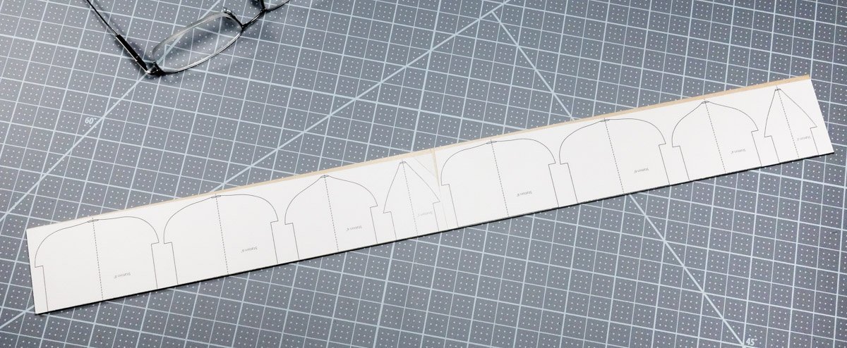
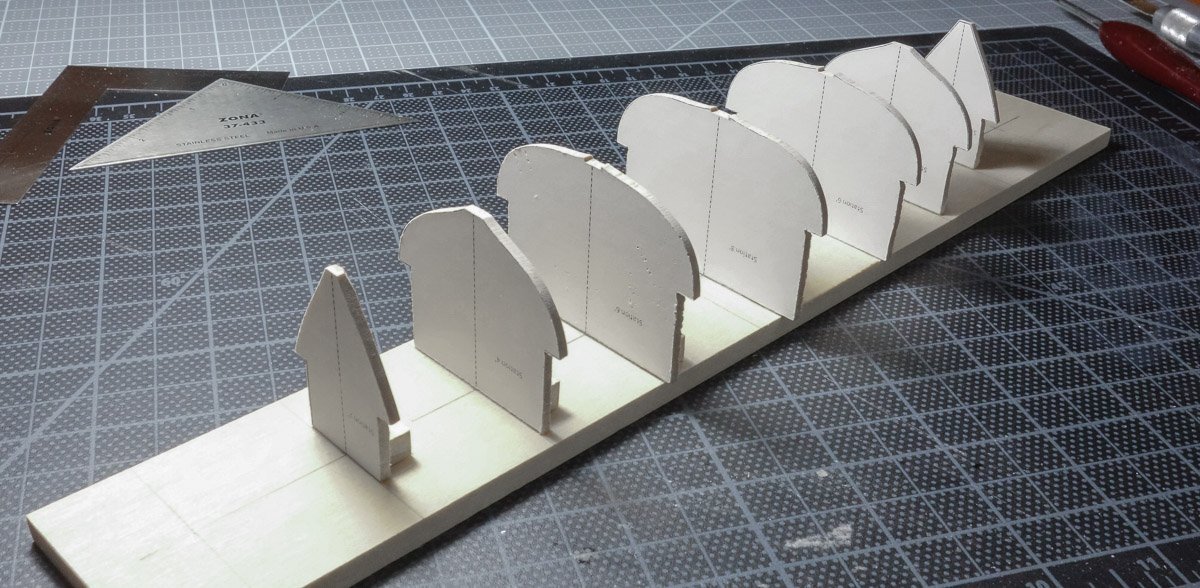
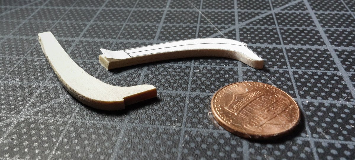
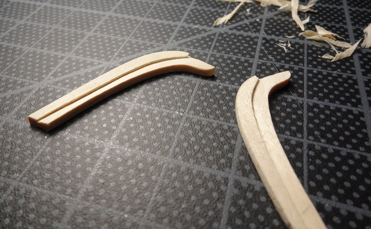
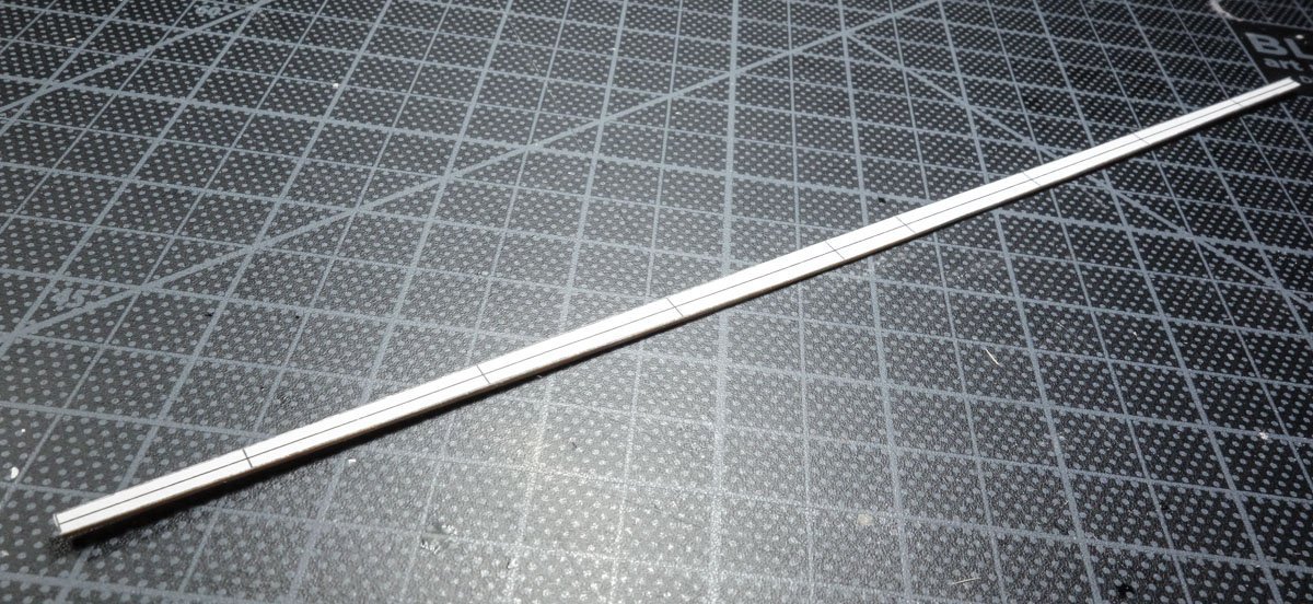
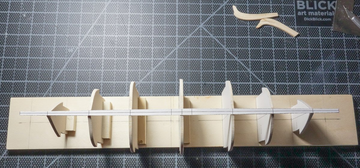
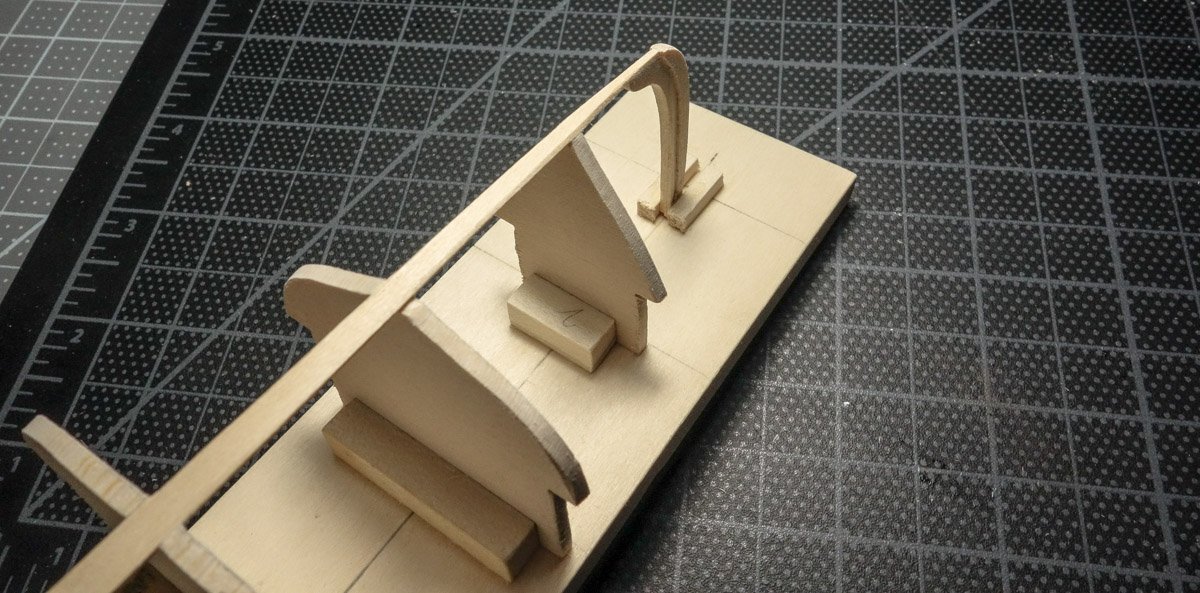
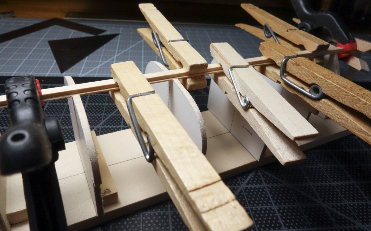
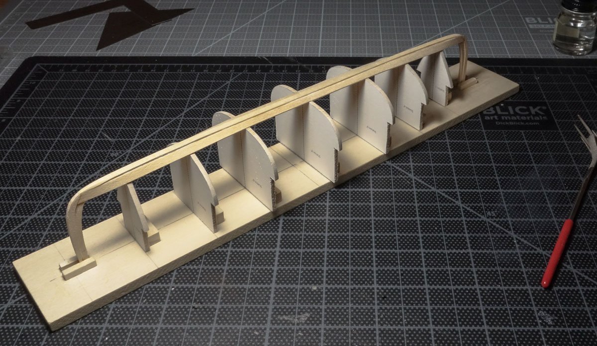
Greeting all and thanks for the comments and likes. Open boat modeling begins with the work of producing a plug or station forms to build the hull over. The final result depends on the quality of the form so it must be done with care. It takes a considerable amount of time to make this temporary form which will eventually be tossed away. It's like nailing together plywood to pour a concrete foundation into. Necessary work, but not very rewarding. I considered not posting any of this form work, because it's been shown many times before, and in all likelihood you have your own preferred or better way to do it. But build logs should be about showing how a thing was done and not just presenting the final result, even if the method is – suspect. So, on that note, I begin with the drawings. The plans come from the book Building Classic Small Craft by John Gardner and they are for a transom stern craft. However, this model will be a double-ended boat and the author states the forward half of the boat has classic lines and all one has to do to build an authentic double-ender is simply mirror those to the rear. This what I did taking care to maintain the 17' LOA. Rather than scanning/photographing the plans and tracing them in CAD, I instead created lines directly from the table of offsets eliminating the possibility of distortions. Here's the body plan. The boat has an inner and outer two-part keel as shown below. The keel changes proportions as it travels the length of the boat, and the width of the inner keel is taken from the drawings. The inner keel is beveled to conform to the shape of the station form it's crossing, and the outer keel is beveled to accept the flat square edge of the garboard. Both keel sections are beveled independently and when they are placed together, the rabbet is automatically created. Between the stations, the bevels are a linear transition. RB 3-02 The four station lines are taken from the body plan, mirrored and the inner keel cutouts are drawn in. The station forms are placed in profile and the form extension lengths are determined. The extensions are added to the station templates. A closer look at one of them. The boat is mirrored at midship, so two printings of the templates are made. They are printed on full sheet labels and stuck to 1/8” (3mm) basswood sheet. Then to the scroll saw, sanding disk and files. I'm inept at using the scroll saw, so I always cut large and sand/file back to the template outline. The forms are squared and glued to the building board. Instead of placing the two forms at 8' side-by-side on the build board one scale foot apart, I used only one, placing it equidistant between the 6' stations. Next, I printed the stem lines and stuck those down on scale 2” thick stock and cut them free. And carved out the rabbet. The inner keel is cut. The keel is glued lightly with PVA to the station forms to keep it in place. It is then beveled to match the contour of the forms. The stems are glued to the inner keel and secured to the building board. The outer keel is beveled and glued to the inner keel. Then the garboards are fitted to the keel on both sides. This was simply a file and fit exercise and didn't cause any problems. The material is 1/32” (.8 mm) basswood and it was soaked in alcohol for added flexibility. Each side is made of two pieces. The full-scale plans call for a plank thickness of 5/16” (8 mm) so the 1/32” garboards are double what they should be. I wanted the extra thickness for added heft and it won't be seen in the final model because the edges will be covered inside and out. But the remaining 10 planks per side will be made from harder material and at the proper scale – 1/64” (.38 mm). Thanks for looking. Gary

- 79 replies
-
- 22
-
-

-
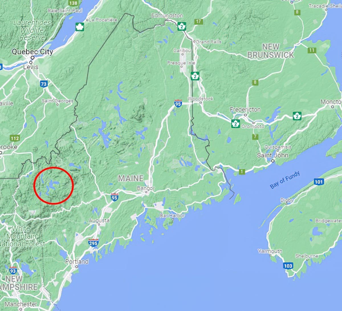
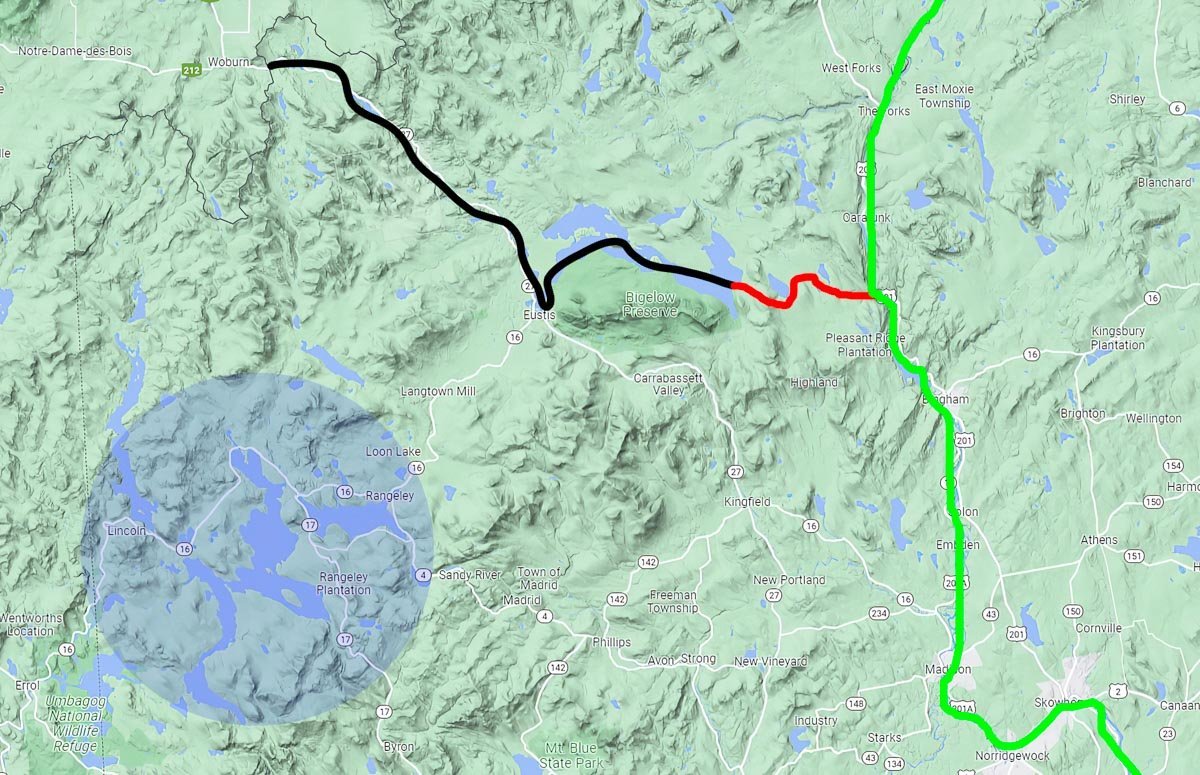
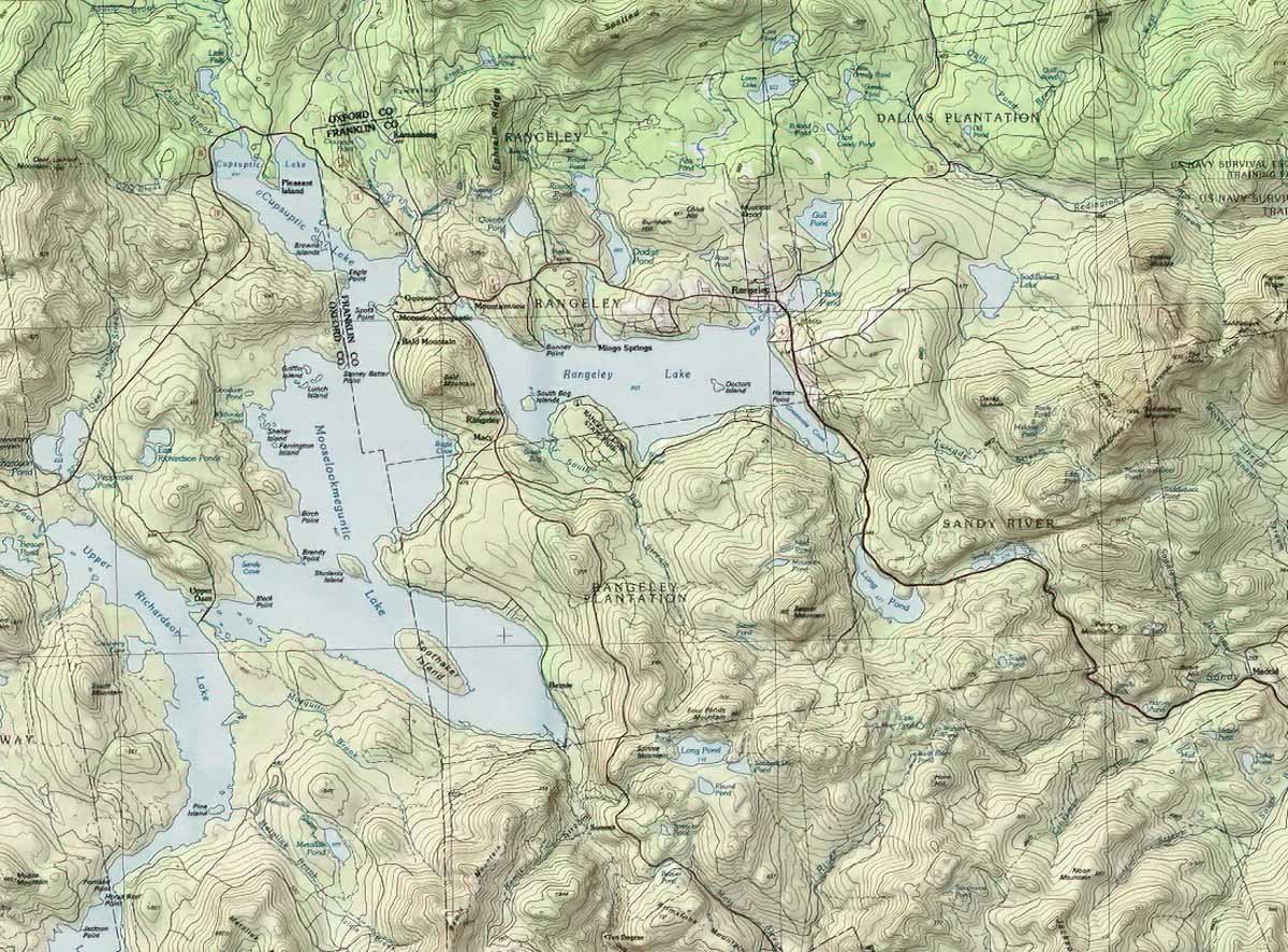
Thanks to everyone for stopping by and for your interest in my modest little project. I'm delighted to know you'll be following. Hello Tom. I think it's a pretty area and worth the drive, especially in the fall. Of course, it looks like New Hampshire and in fact much of the upper Androscoggin watershed is in the northern part of your state. Thanks for following. Hello Roger. The Arnold expedition did not pass though the Rangeley Lakes area. As you correctly stated, the expedition route came up the Kennebec River which is east of the area now known as Rangeley. About 100 miles up the Kennebec from the coast, the expedition left the main water course and headed west up the Dead River tributary which they would follow to the high point of land near what would eventually become the Canadian border. But the Dead River was unnavigable where it joined the Kennebec and the force of 1,100 men were compelled to portage 13 miles over rough terrain gaining 1,000 ft in elevation before they would reach the North Branch of the Dead River. The men carried several hundred wooden bateaux each weighing 400 pounds plus tons of equipment, food and supplies. Some of the men made several trips and all endured extreme suffering and starvation. And it would not get any better from there. This portage route was well known to the native peoples of the region which they named the Great Carrying Place. I've roughly traced the northern section of the route on the map below so you can see where it is in relation to the Rangeley area. And it is close - but it is indeed a separate drainage basin. The green line is the Kennebec, the black is the Dead River, and the red portion is the Great Carrying Place. I recommend Arundel by Kenneth Roberts which chronicles this Maine leg of the Arnold expedition. It's a historical novel written ninety plus years ago and like all novels it is a work of fiction, but it's highly regarded by historians and sticks to the central facts and details of the event. In 1775 this was raw, remote and unforgiving wilderness. Roberts' writing is clean, urgent and puts you there. As a younger man, I spent a week or so on the waters of Voyageurs National Park and I agree there is a similarity to northern New England. They both have that same deep-woods feel, moose, the otherworldly call of the loon and mid-summer mosquitoes the size of Mallards. My kind of place. Thanks Roger. The boat will be built upside down over the station cross sections. Obviously, the planking will not be glued to the stations only formed over them. Thanks for your interest Wefack. And thanks again to all for looking in and I'll have some headway to show very soon. Gary
- 79 replies
-
- 10
-
-
I'm sure this will turn out nice Keith, whichever spacing you decide on. I totally agree with Mark's post below. The ability to soften and remove what doesn't turn out as planned is huge. Just my two cents. Gary
-
Brig Le FAVORI 1806 by KORTES - 1:55
FriedClams replied to KORTES's topic in - Build logs for subjects built 1801 - 1850
Alexander, I am angry and saddened by the events taking place in your country. I wish you and your family safety and peace. Gary -
I too am deeply saddened by the events unfolding in your country. I wish you and your family better days ahead. Gary
-
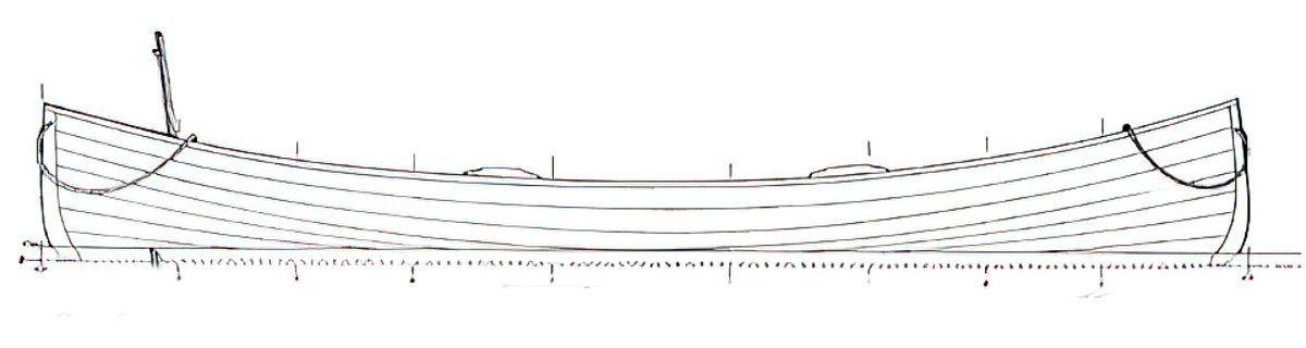
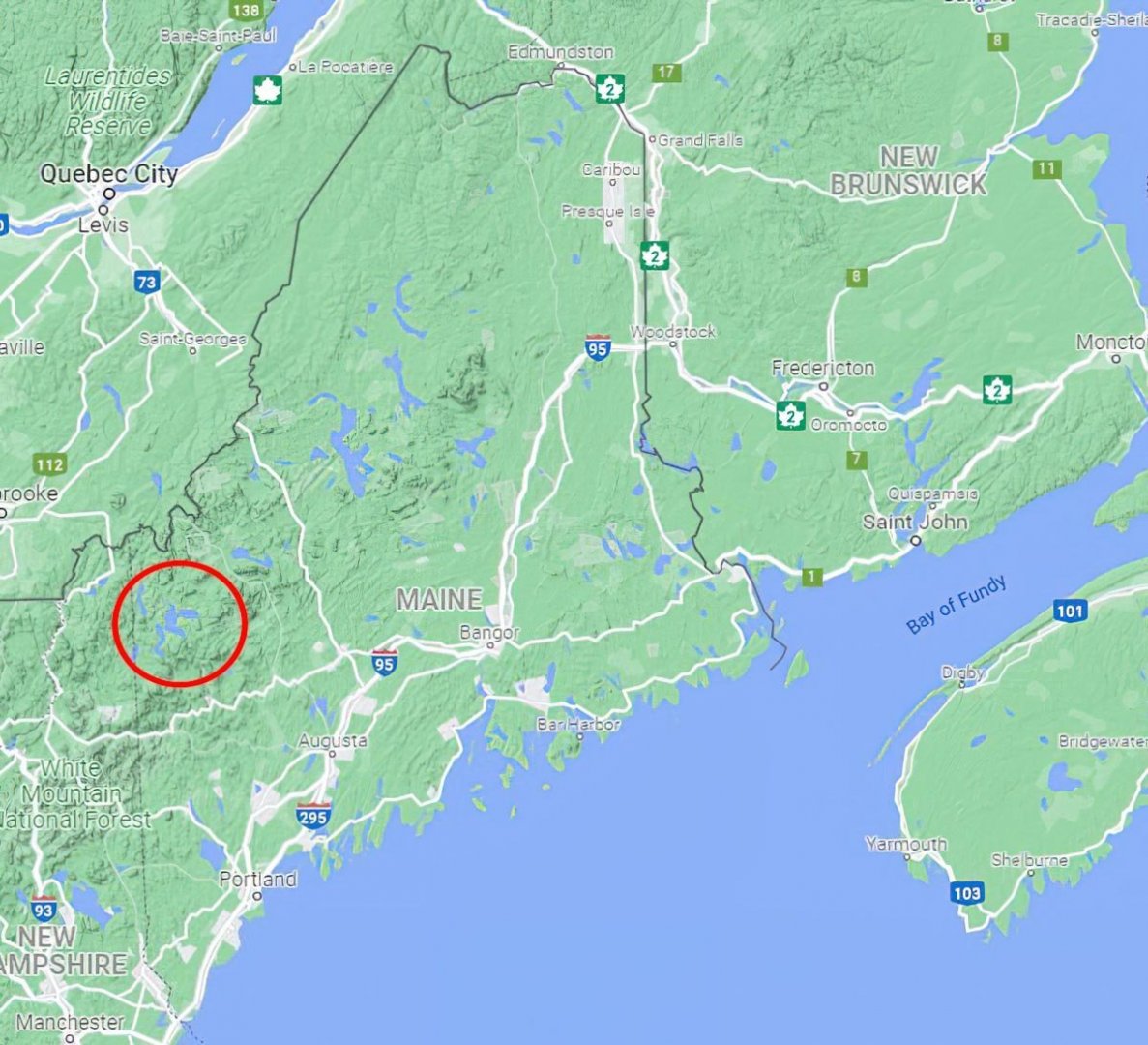
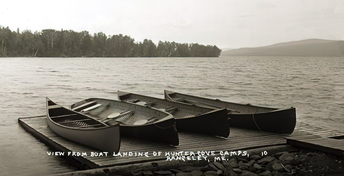
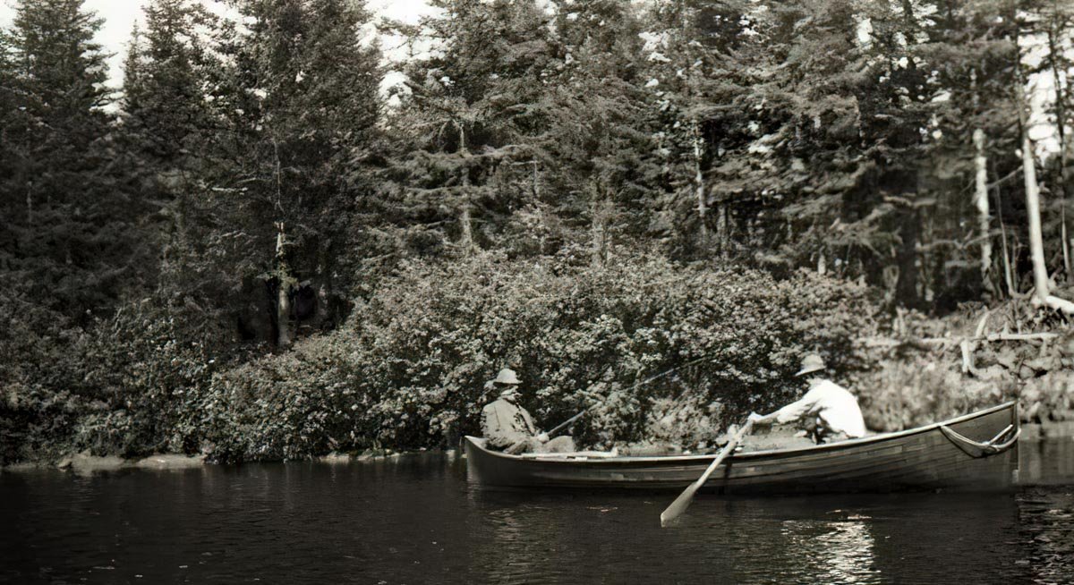
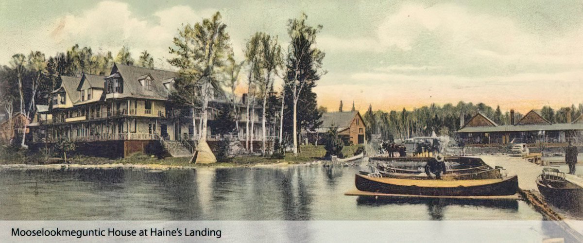
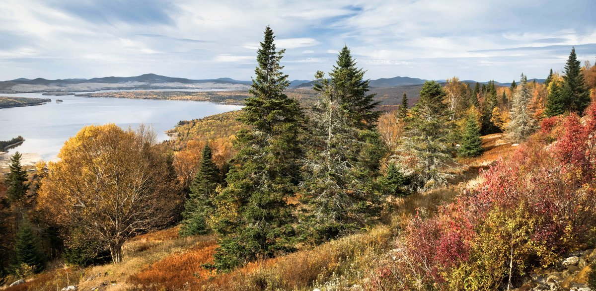
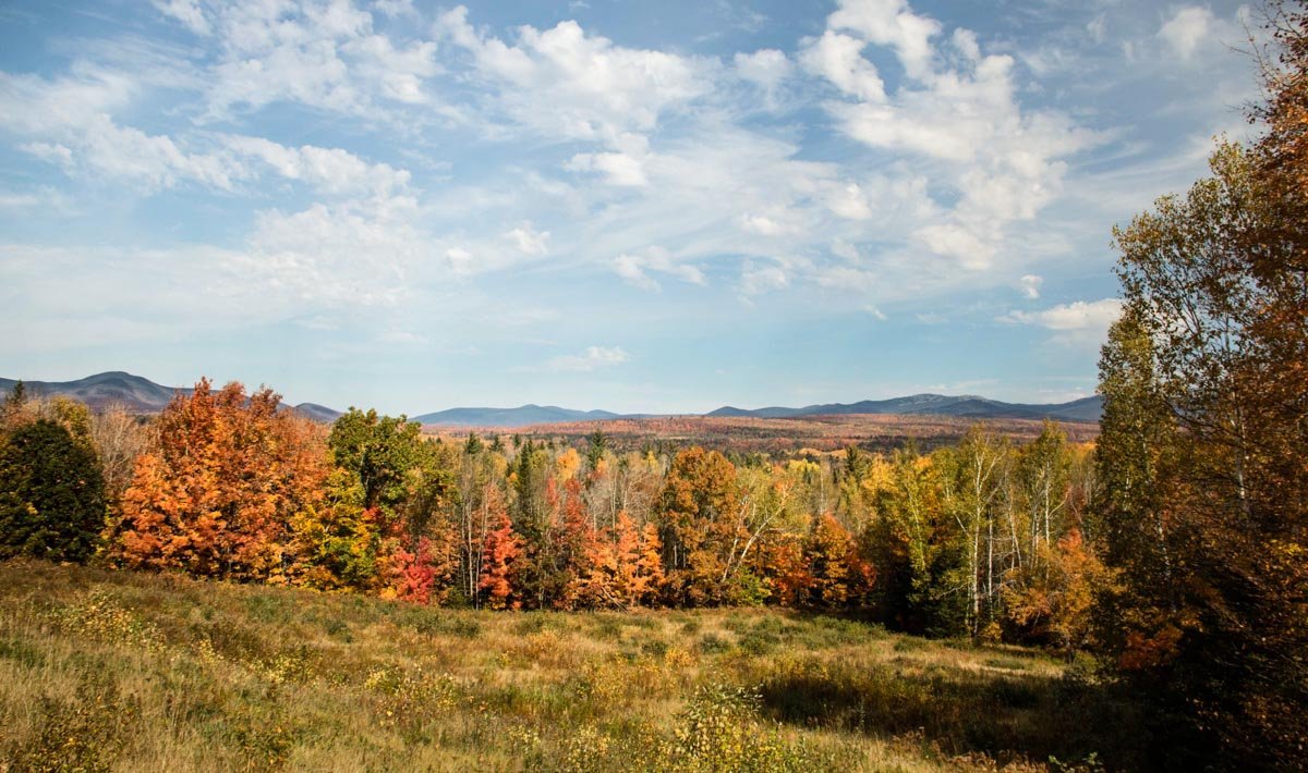
Greetings fellow modelers. I'm starting a new scratch project of an inland waters boat called a Rangeley. The model will be built in 1:18 and have a total length of about 11” (28cm). The lines for this project are adapted from John Gardner's wonderful book Building Classic Small Craft. It is a lapstrake constructed open boat with a 4' beam and 17' LOA. But departing from Mr. Gardner's plans, this will be a double-ended boat instead of a transom stern. From Mystic Seaport Museum website The Rangeley boat derives its name from the Rangeley Lakes region in western Maine where it originated primarily as a guide boat for fishing but was also used as a gunning boat for waterfowl. The region's one hundred plus lakes and ponds are part of the upper Androscoggin River Basin and has long been a draw to outdoorsman in general and fishing enthusiasts in particular. In the late 1800s and early 1900s these were perhaps the best know native brook trout waters anywhere. During this time period, wealthy families from industrialized areas to the south began to “summer” in the area for recreation and to escape the hot crowded cities in a world before air conditioning. They came to enjoy the cool fresh air, the sparkling clean waters and to fish, hunt, hike, picnic and rejuvenate. These “Rusticators” stayed at camps (cabins) and lodges and hired local guides to take them out onto the lakes and ponds for bird hunting and fishing excursions. The period images below are from the Penobscot Marine Museum in Searsport, Maine. The first image shows two double-ended Rangeley boats and one with a modified stern – even a canoe for size comparison. The first Rangeley guide boats were built in the 1870s for members of “angling associations” and were fashioned after some of the boats found in the Adirondack area of upstate New York. The design was changed and adapted to suit the sometimes shallow and often rough waters of the region. The flat bottoms provided a stable platform for stand-up fly-fishing and the round seats provided maneuverability and helped keep the inexperienced in the center of the boat and out of the water. Typically, the thwarts had built in trays on both sides of the seat for tackle and other gear. Early boats were always double-ended and later modified to flat transom sterns to accommodate the small outboard motors that were becoming popular in the 1920s. Until recently, I had no intention or even a though about modeling a Rangeley. But a day outing to the area with my wife this past October planted the seed in my head and has since germinated. Mooselookmeguntic (pronounced just like it looks – really) is the Rangeley's largest lake at 16,300 acres. A portion of it is visible in the photo below which was taken at the “Height of Land” pullout. Fishing in the Rangeley Lakes remains popular and productive to this day. Some of the sought-after species are landlocked Atlantic salmon, lake trout, rainbows and browns and the area still boasts some of the best brook trout habitat to be found. This should be a rather quick build (he says) and I invite you to stop by on your travels around the forum. Thanks for taking a look. Gary
- 79 replies
-
- 21
-
-
Nice work Ken. I think your rope coils look good and hang quite naturally, especially those up in the bow. Very Nice. Gary
- 238 replies
-
- 3
-
-
- sloop
- providence
- (and 1 more)
-
Masterful work once again Valeriy. Such excellent craftsmanship. And I really like that point-of-view photo in post 682. Gary
-
Very nice progress Egilman - the engine looks great, and I like the way the landing gear turned out as well. Keep it up. Gary
-
Way to go Keith - I knew you'd hang tight. Anything that works is kosher and the result looks great. Nice job. Gary
-
I’ve pulled up a seat to follow along. Looks like a really nice kit and I’m sure you’ll make a terrific job of it. I am especially interested in seeing the bare metal rendering as I’ve never done anything like it myself. Best of luck on this new project Egilman. Gary
-
I feel your pain Keith. I hate when everything attempted goes wrong or makes matters worse. During periods like that I always put the damn thing out of my sight for a week or so and return to it after my blood pressure returns to normal. I never do solid modeling when I try to force a fix. Step back and take a breath - you’re a talented modeler - you’ll find a solution. Gary
-
More amazing work Wefalck. It always an education catching up on your progress - and enjoyable as well. Gary
-
Congratulations on the completion of two very nice models Egilman - they turned out great. They both have a very authentic look and feel. Very nice! Gary
-
Dang -that is beautiful painting. Very nice progress. Gary
- 2,696 replies
-
- 5
-
-
- heller
- soleil royal
- (and 9 more)
-
You've made a lot of progress on these birds since I last checked in and they are looking great! Excellent scratch work on the litters and everything carefully researched. Very nice work Egilman. Gary