Jump to content
Supplies of the Ship Modeler's Handbook are running out. Get your copy NOW before they are gone! Click on photo to order. ×

FriedClams

NRG Member
  • Posts

    1,357
  • Joined

  • Last visited

Everything posted by FriedClams

  1. Excellent model Grant and congratulations on its completion. Such careful and exacting execution - very nice work indeed. Gary.
  2. Nice update Keith. I couldn’t help but notice that every yard is level and perfectly inline with the others from every camera angle. I'm sure that took some time and fiddling to get right. Very nice. Gary
  3. Thank you all very much for your kind words and generous appraisal of the diorama. It means a lot coming from such a talented group of modelers. This dio has been great fun due in large part because of you folks here at MSW and I thank you for that and for allowing me to share it with you. I look forward to catching up on all your projects. Gary
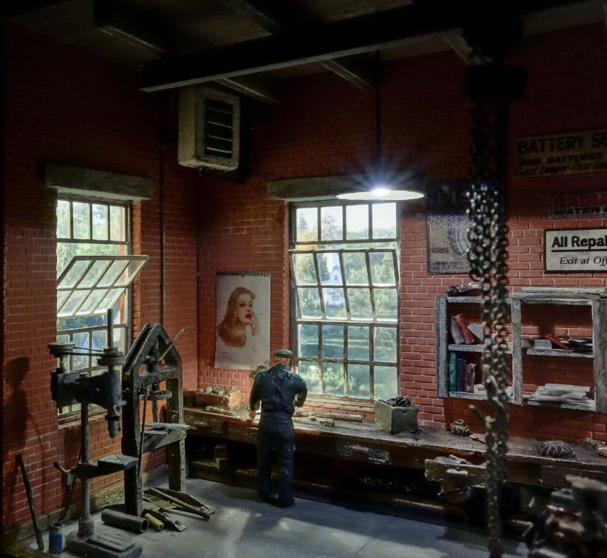
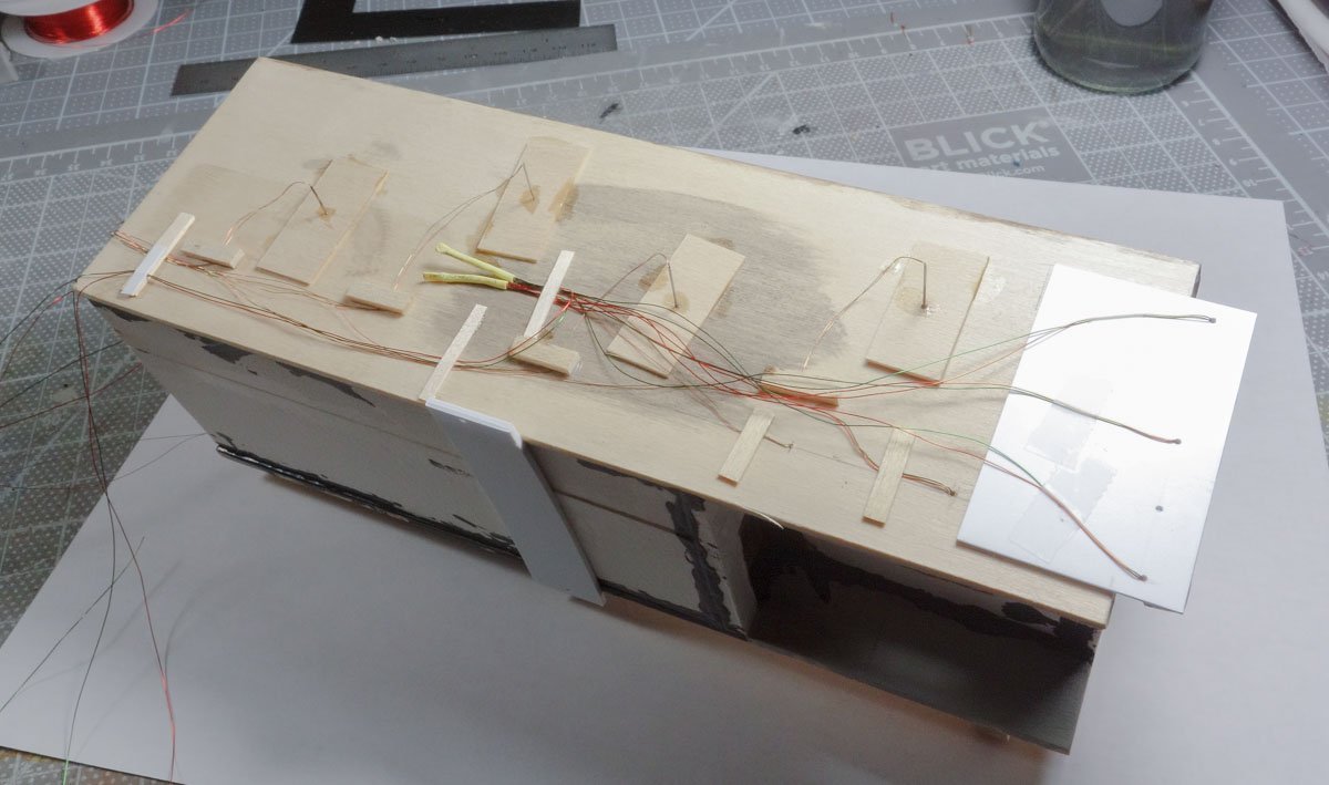
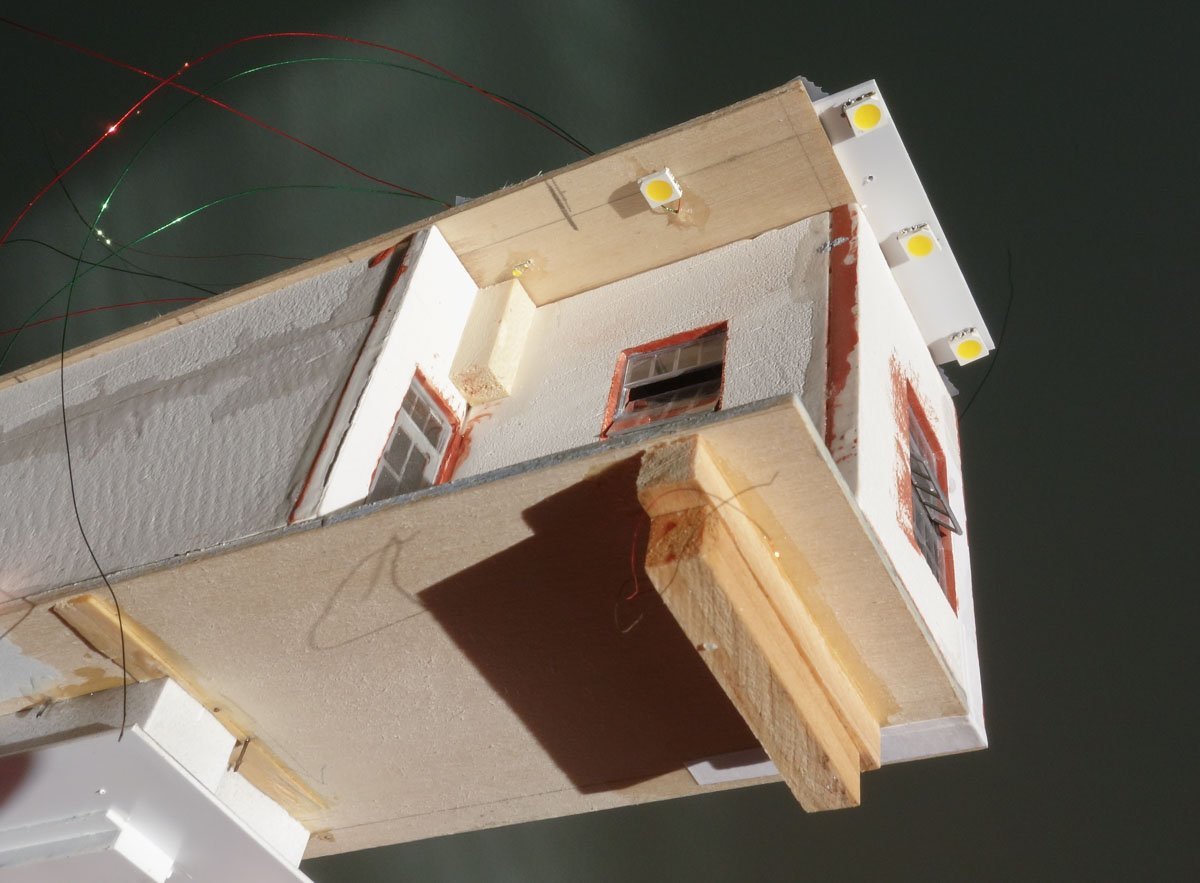
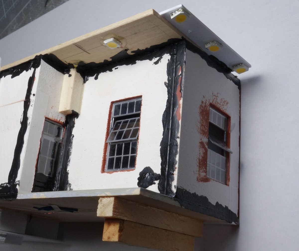
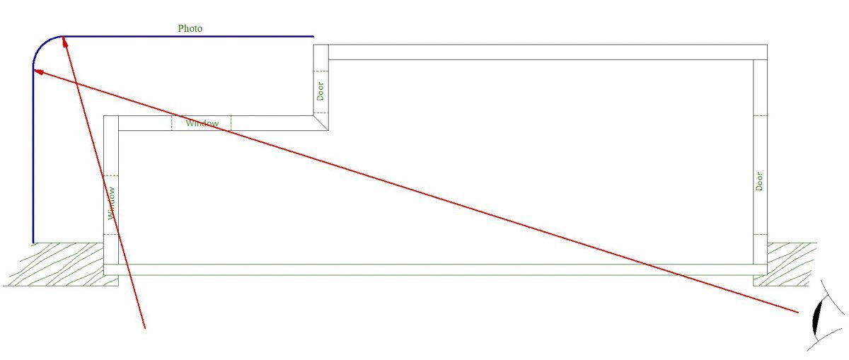
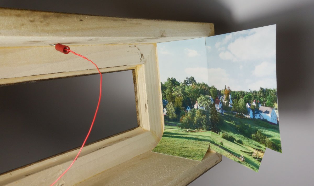
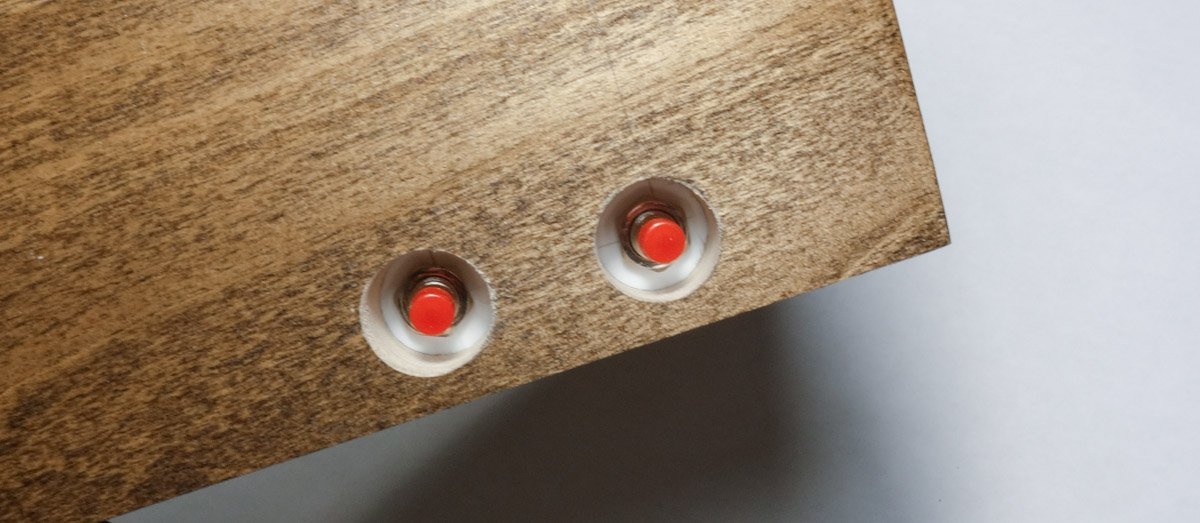
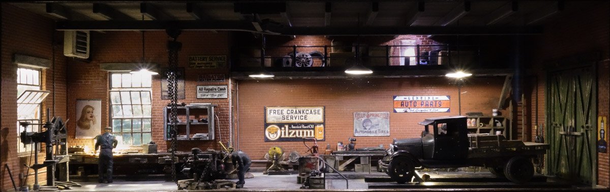
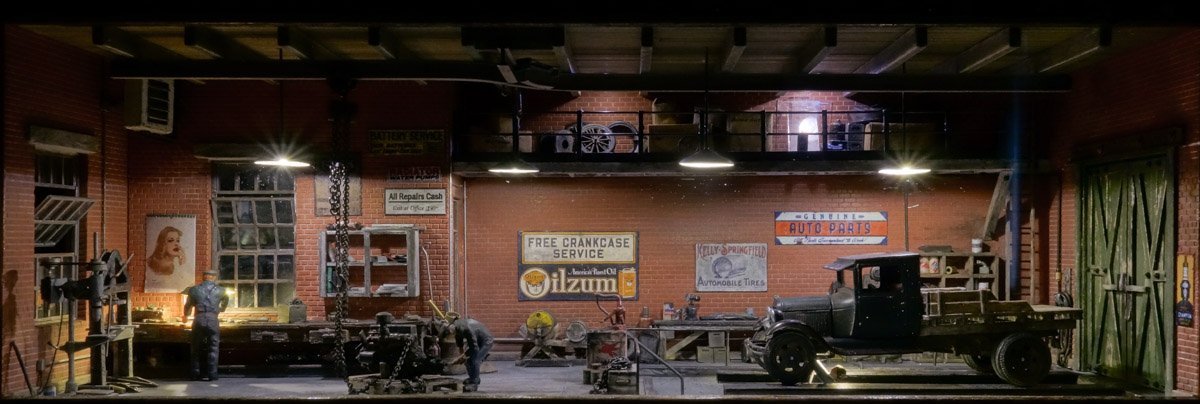
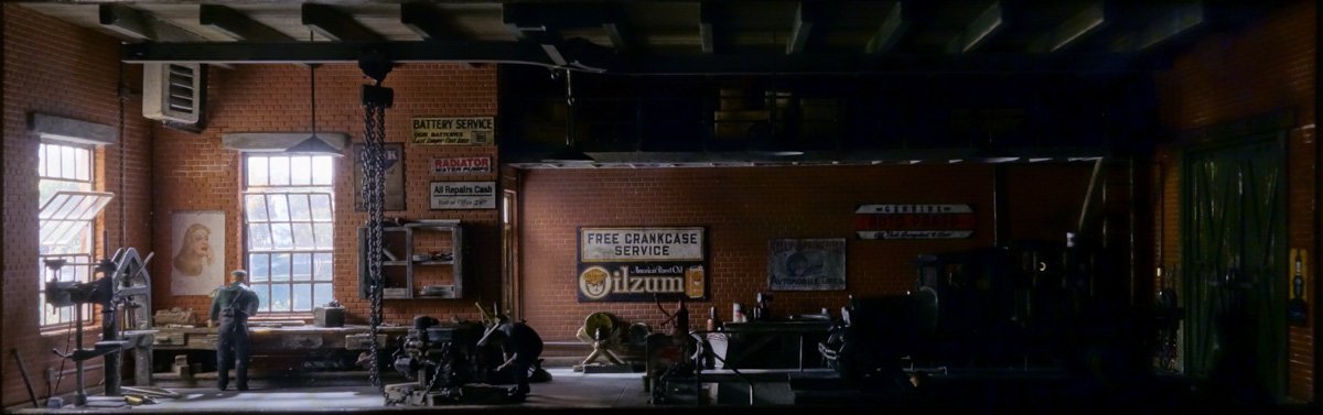
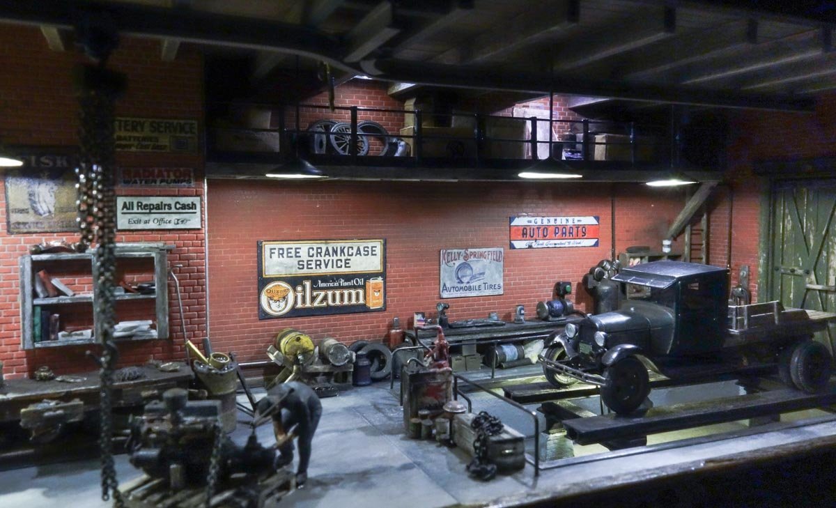
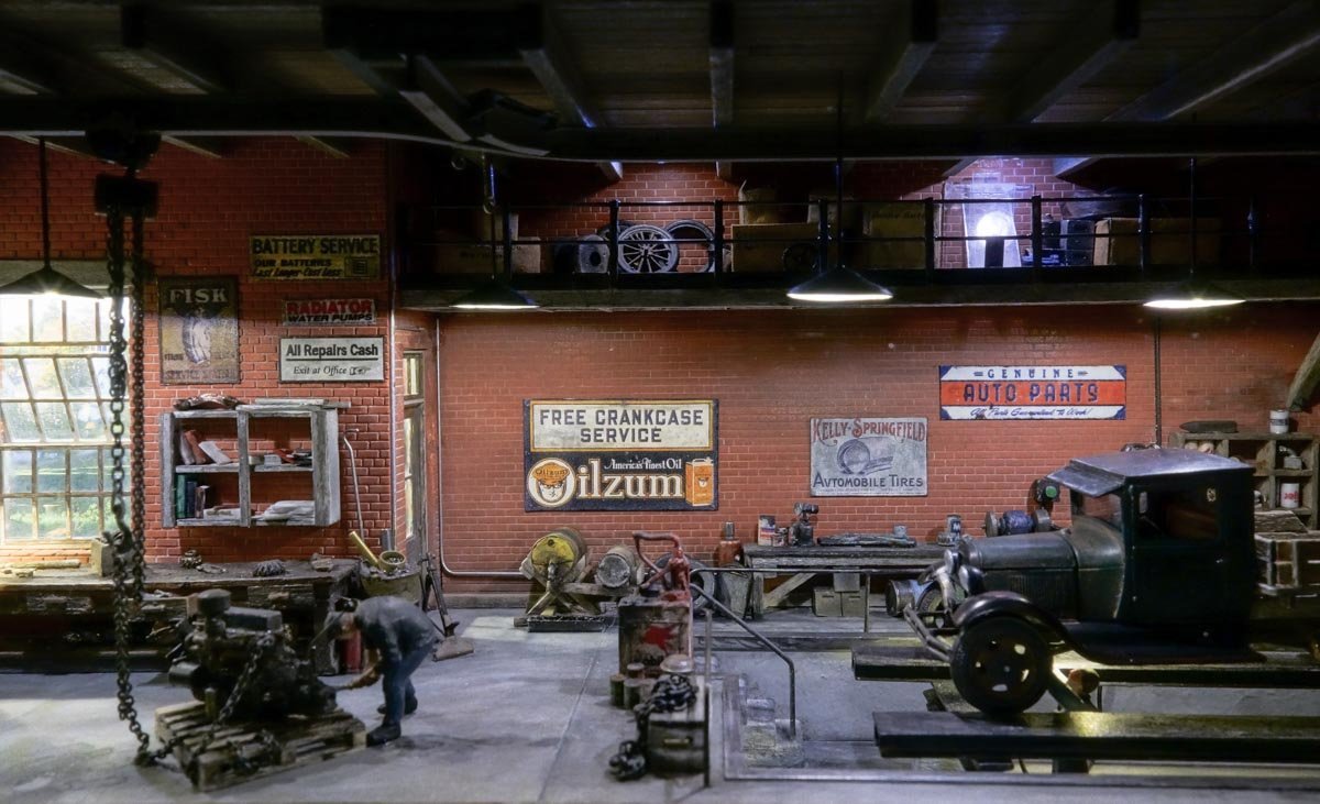
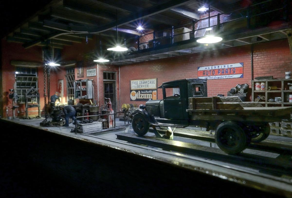
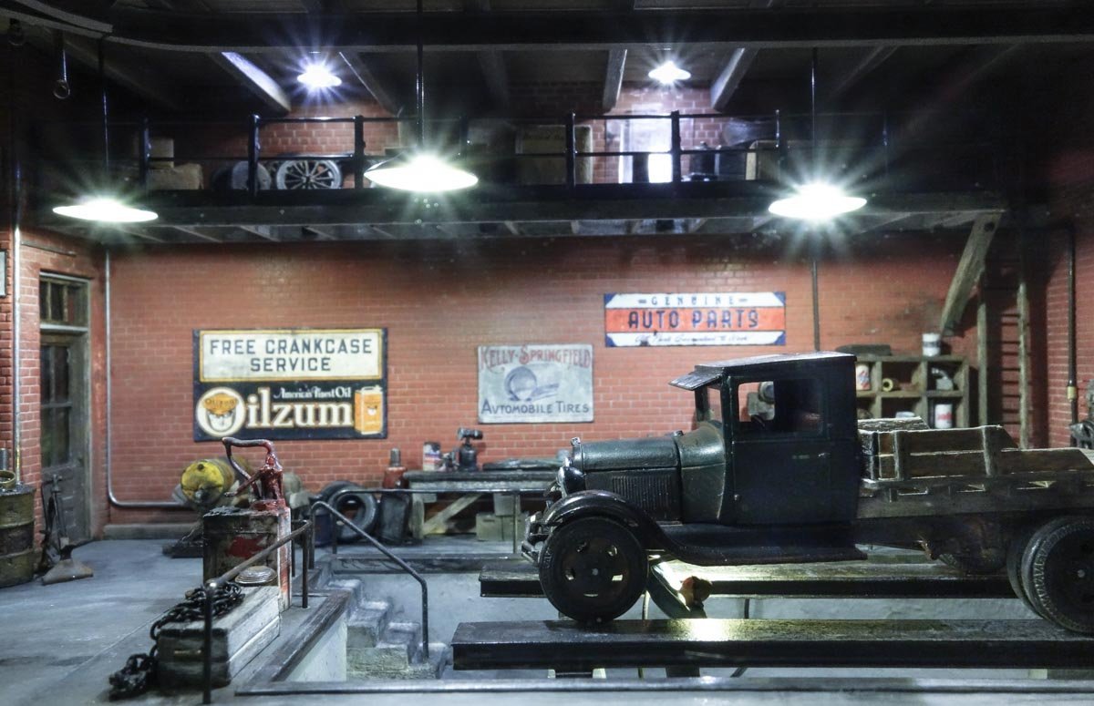
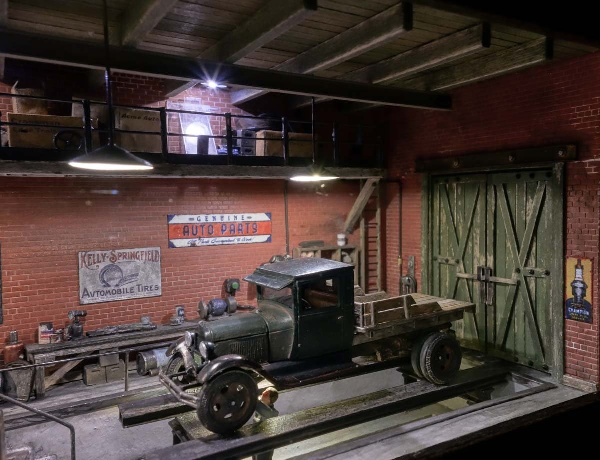
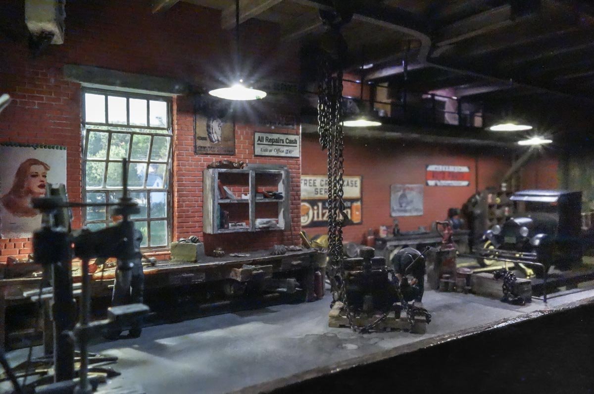
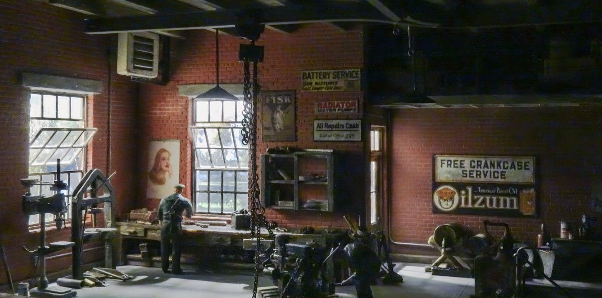
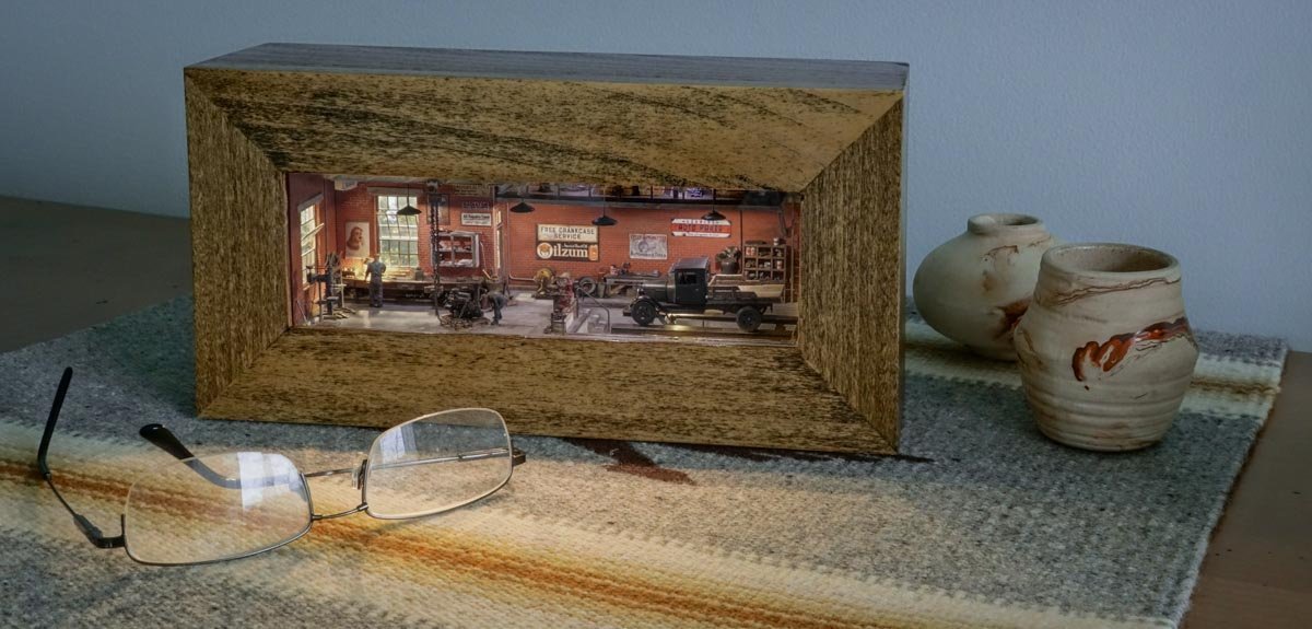
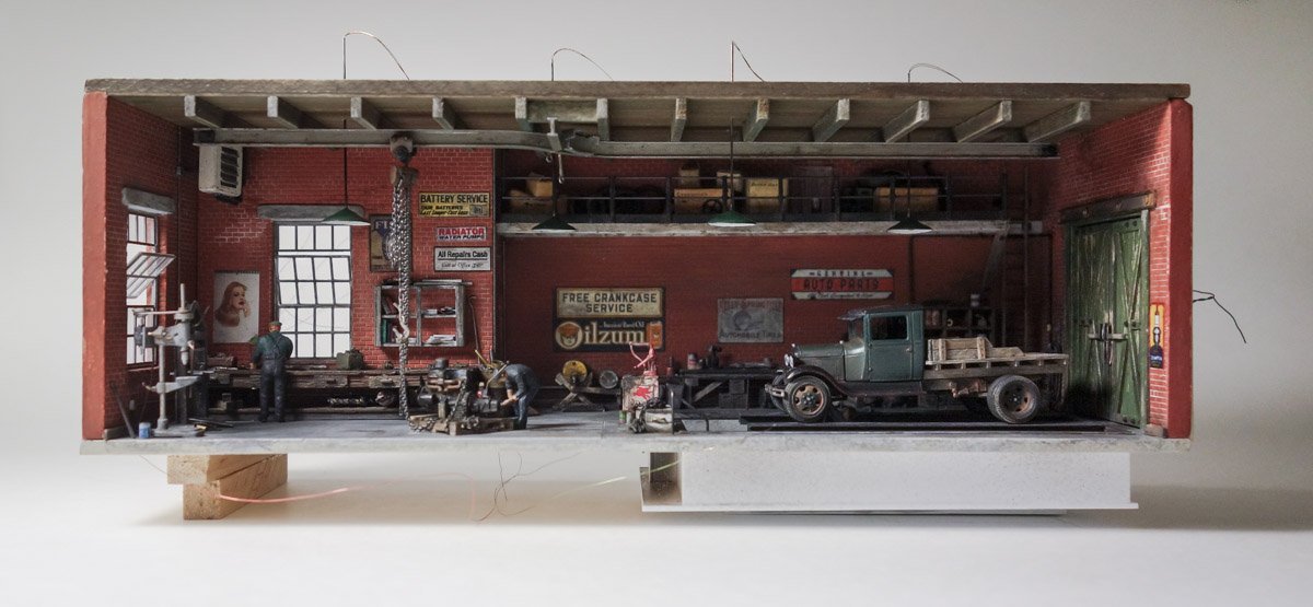
  4. Greetings fellow modelers. The last item to finish on this diorama is the exterior (through the windows) lighting and the wiring. A styrene bracket overhangs the end of the building and LEDs are glued to the underside. There are four warm white 5050 diodes and a single 0805. The 0805 fills in the area above the door. This model is a lot like real estate – it looks OK until you walk around back. The black smeared all over the seams is a PVA and acrylic paint mixture and keeps the light from shining through the cracks. In fact, I've painted the back side of the thin plastic door with the goo to prevent it from glowing as the bright light makes it almost translucent. Originally I had intended on using an industrial/commercial scene, but decided instead on an image with colors that would feel more like a sunny day and contrast with the drab interior. The scene also needed to be a subject that could be wrapped 90 degrees through the corner which would be difficult to do with close up buildings. The line-of-sight created by the window positioning necessitates this continuous scene because it allows for viewing positions where the side wall and the back wall can be seen at the same time through a single window. So two separate scenes (one out the rear window and one out the side) can't be used. The trimmed-to-fit image is attached to the side wall and the back gets folded in after the dio module is inserted. The flare of the lower portion of the photo keeps the viewer from seeing the inside bottom of the shadowbox. The red wire along with an identical one on the bottom holds the dio in place up tight within the face frame inset. Two latching push buttons are recessed into the bottom - one for the interior and one for the exterior. This recess gives me the option to set the shadowbox down on a horizontal surface if I chose not to wall hang it. The lighting is controlled in 3 main groups with each group having its own PWM (Pulse Width Modulator), so I can adjust their light levels up or down if need be. The groups are the 5 exterior lights, four pendant lights and two mezzanine lights. The bench light and pit light are separate with a fixed output. Here is the final result. None of the images are focus stacked and the star-like rays coming from the lights are due to the use of a wide angle lens, a very small aperture and long exposure times in attempt to gain the greatest depth of field. Also, they are not HDR composites although I did open up the shadows in software on some of the images which gives them an HDRish look. All lights on. Interior lights only. Exterior only. All Interior only. Exterior only. Thanks to all for stopping to take a look and for the likes. And I especially want to thank everyone who left comments. Your encouragement, suggestions and input made this a better model than it otherwise would have been – and much more enjoyable as well. Thank you so much. Be safe and stay well. Gary
  5. Nice progress Dan. Did you put the flats on the tires or did it come molded like that? Either way, it's a nice detail and will give the model visual weight. I've seen guys do something similar to truck tires - soften them with heat and squashing them them down to produce a little side bulge. Gary
  6. Nice work Keith! As others have already stated, a very helpful tutorial and an excellent result. That goes in my notes folder. So, how many more do you have to go - 435 ? Gary
  7. Fabulous work Valeriy! I know I've said this before, but your work is so precise, clean and meticulous. I also know that it takes dedicated hard work to achieve such a result. I've been looking at your brass and wood capped railing and it appears flawless. Bravo! Gary
  8. Greetings fellow modelers and thanks so much for the wonderful and generous comments - I do appreciate it. Thanks Eric and I'm glad you found my small build. I'm pleased it has given you some ideas for future projects. Hello Druxey. Yes, the walls do look a bit too clean now and I might darken them around the bench especially. But first I want to get the interior lights going and see it as a completed whole before deciding what, if any more dirtying needs to be done. Thanks for stopping by. Hi Mark. As Egilman has stated, 1:87 is what model railroaders call HO scale and is the most popular scale for that hobby. Although I'm not a railroad modeler, I do model in HO often to take advantage of the detail items that are available in this scale. The brick wall blanks, the figures, injection molded window frames and the 29 Ford kit are the items that made the diorama easier to build and more pleasurable. All these items could of course be scratched, but I wouldn't enjoy the process and if I were intent on scratching everything, I would choose a larger scale - like 1:48 or 1:35. So 1:87 is a good scale to scratch what is interesting or unavailable and buy detail parts for items that are tedious or that someone else has already done better. Hope that answers your question. So, I'm waiting for a couple of latching push button switches to be delivered to complete the diorama. I hope to show you the final result soon. Thanks for looking. Gary
  9. Excellent work FF - looks absolutely real! Thanks for tip on the fly tying clips. I want a handful of those. Gary
  10. Wonderful exacting work Brian, as I always know it will be. The boats came out great and the canvas is very believable. Your modeling is always very complete and you never skip over the small details - like pipe hangers, or elbows on your steam piping - excellent, I love the surprise of the unexpected. Nice grey base color too. There’s just something about raw umber that adds a deep, complex look of age. Gary
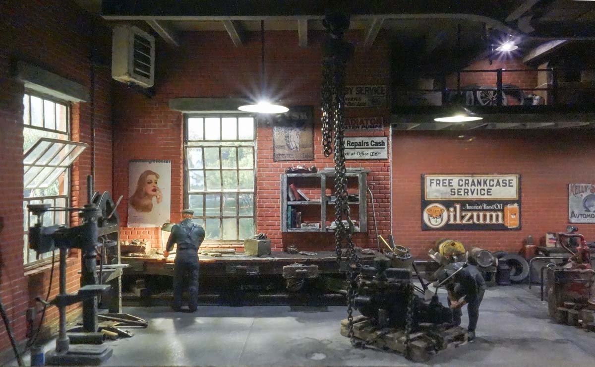
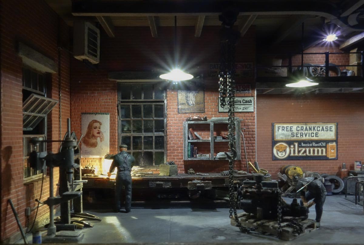
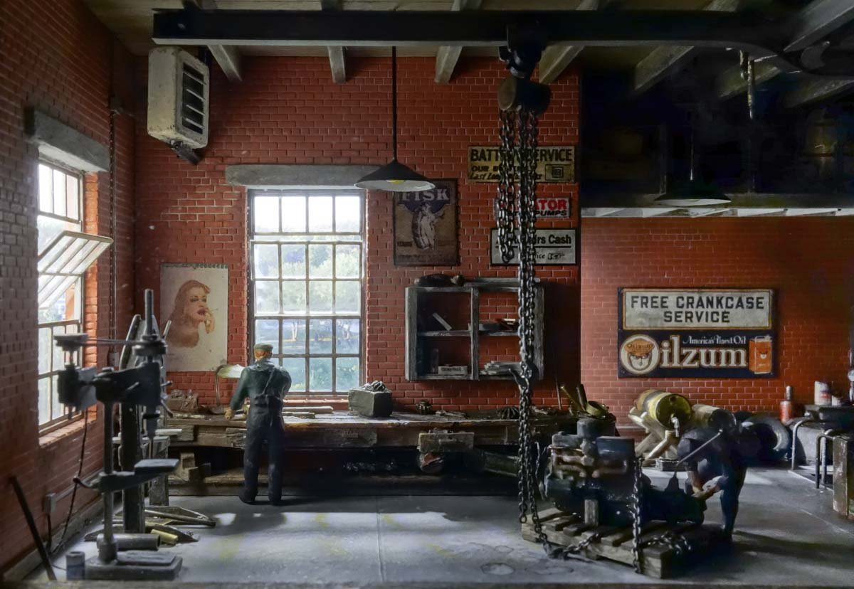
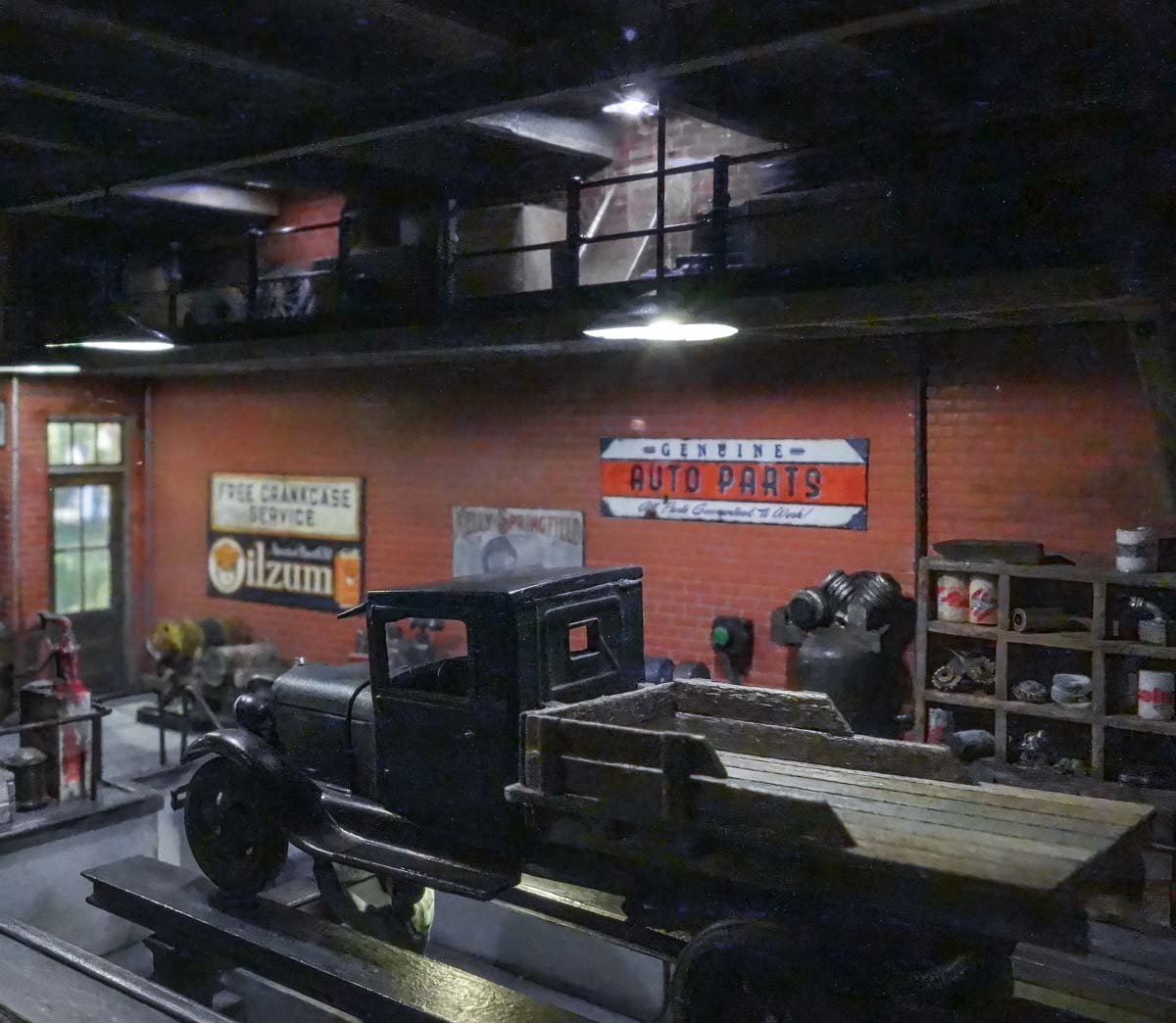
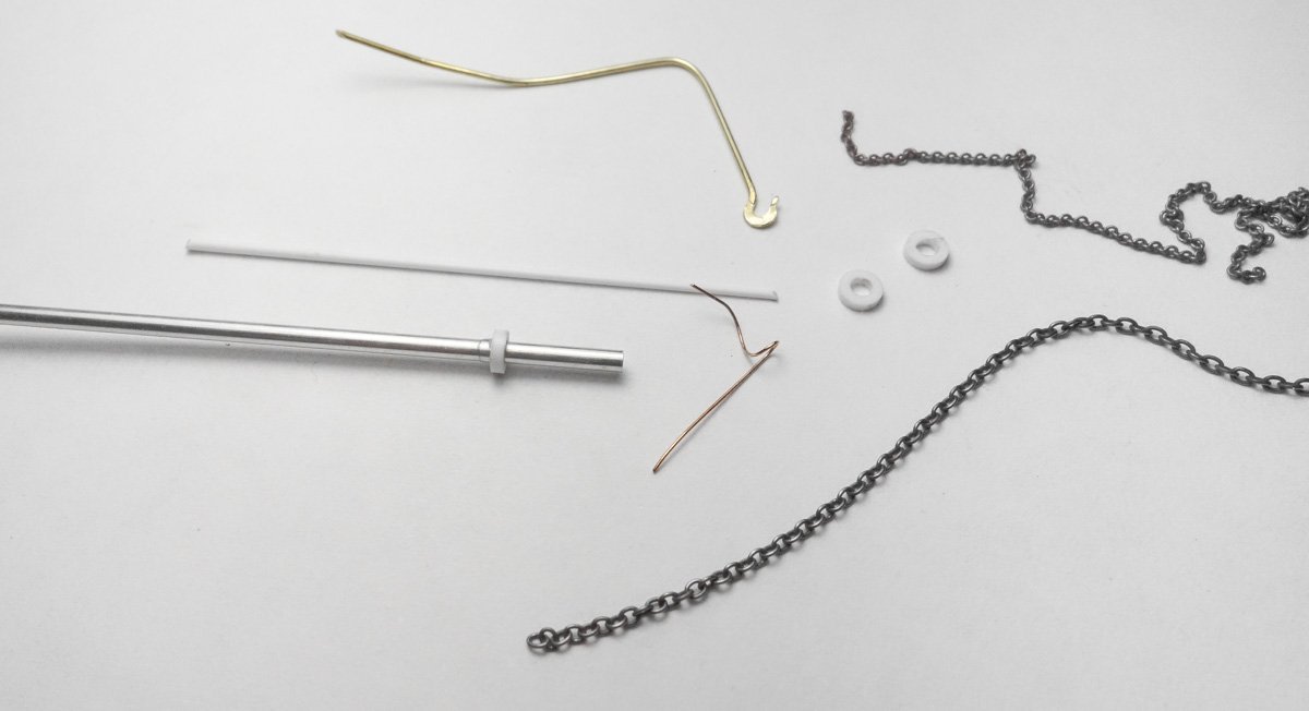
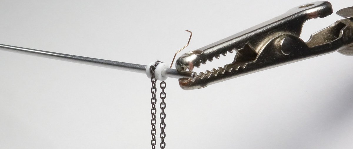
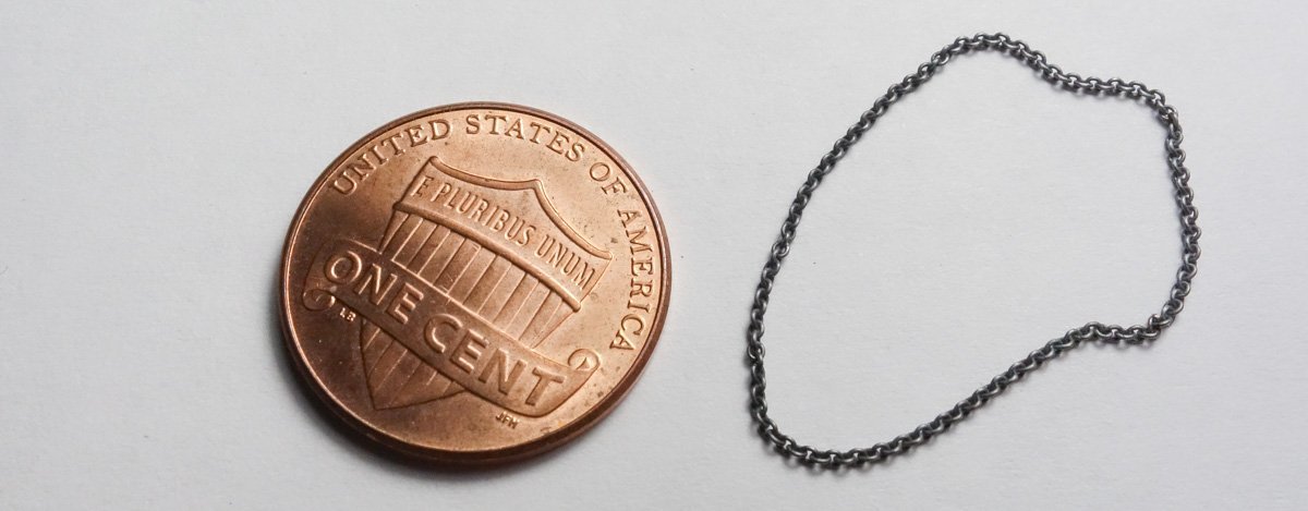
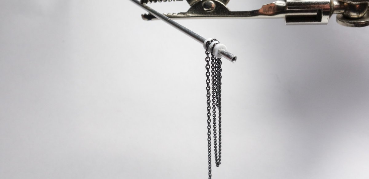
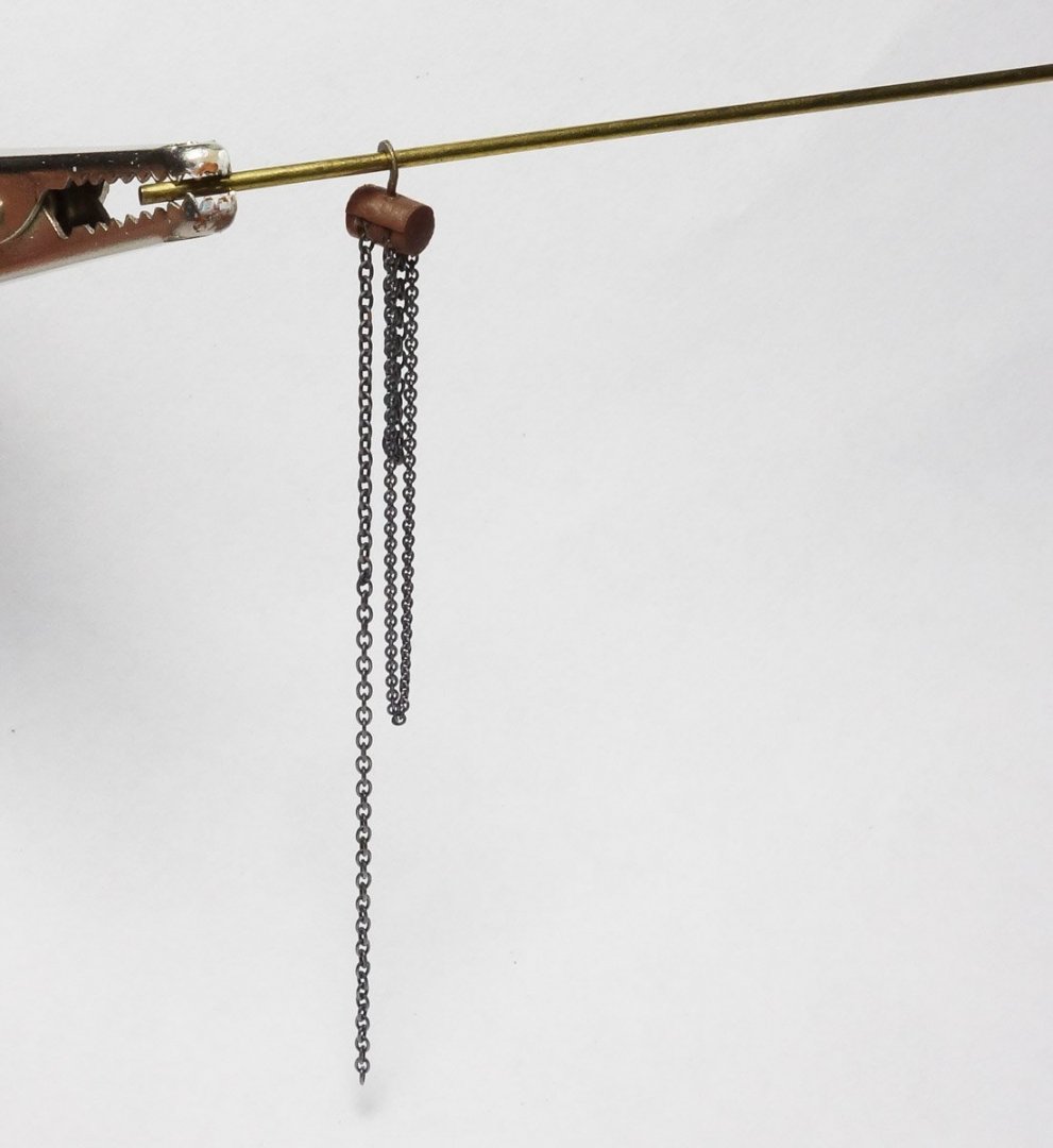
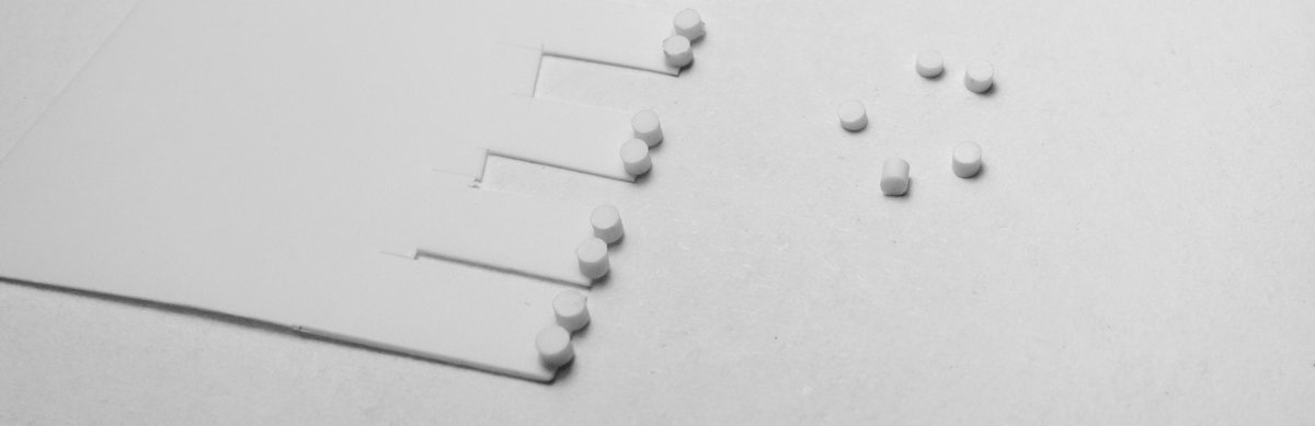
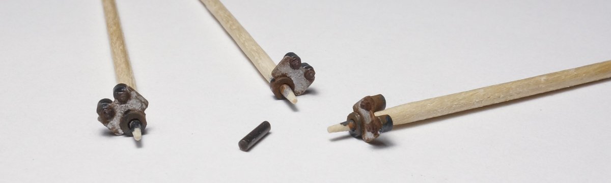
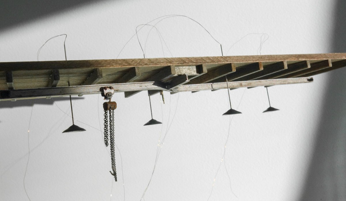
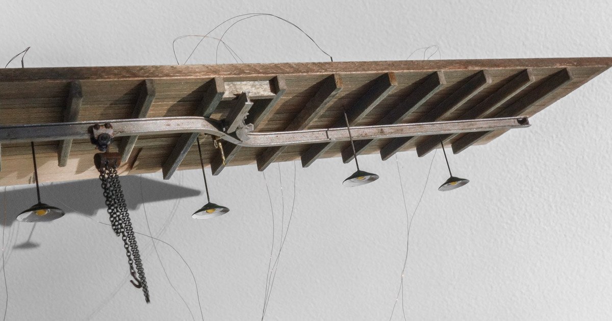
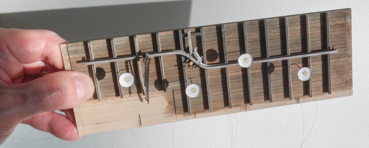
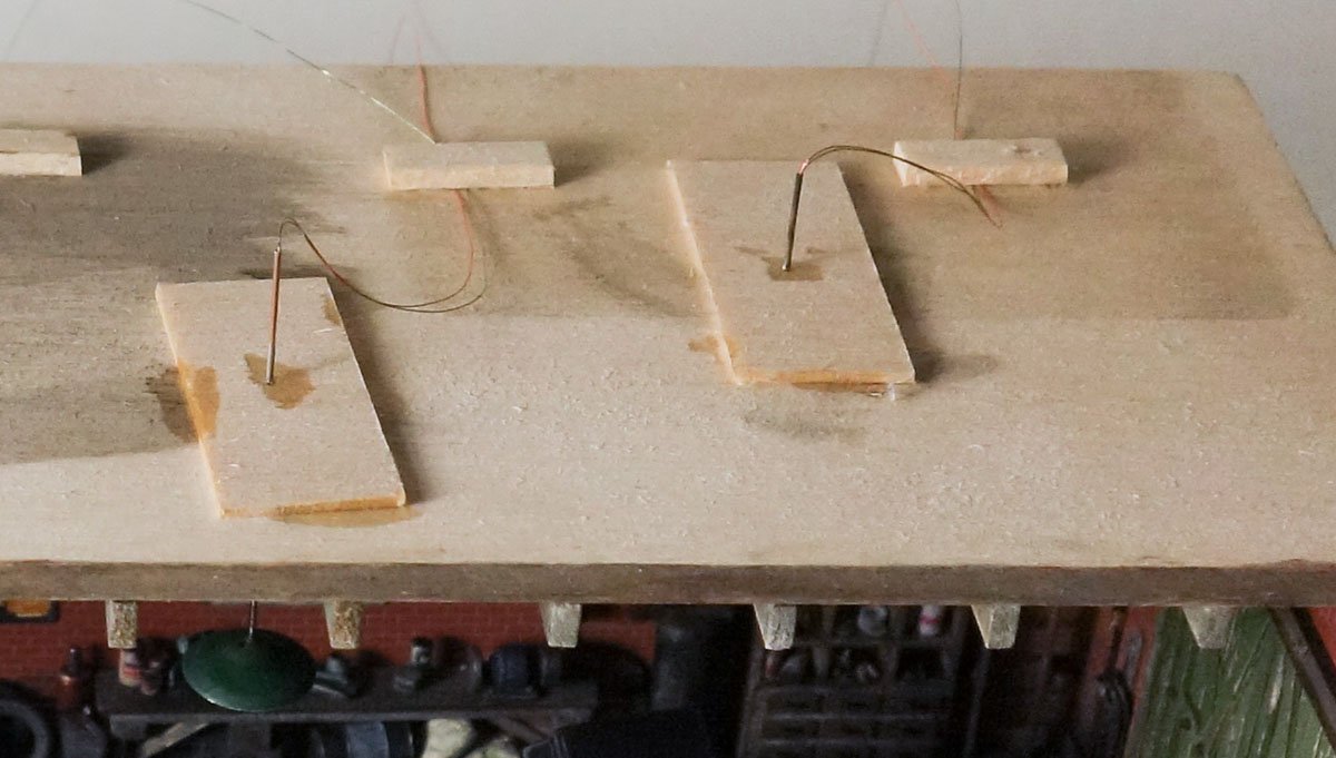
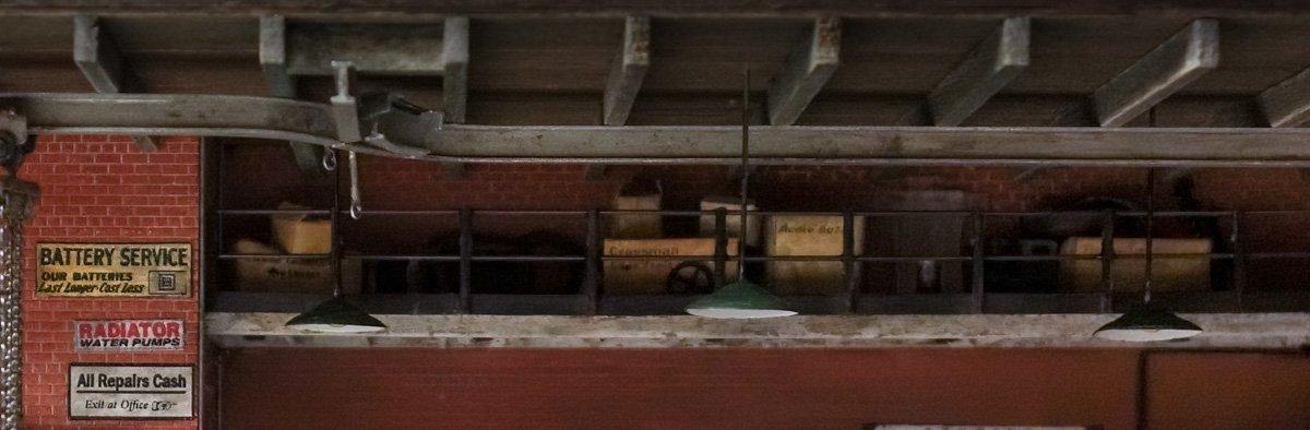
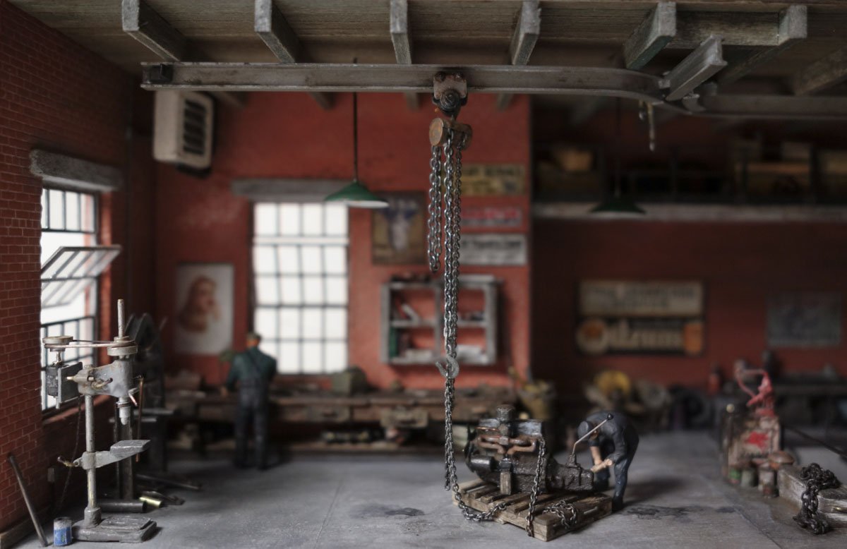
  11. Gentleman, thank you one and all. A short update. The last item to make for the diorama is the chain hoist. The process starts with gathering up the materials. The small chain is 40 links per inch and the larger is 27 lpi. Slices of styrene tube are slid over 1/16” aluminum. The load chain (27 lpi) is draped over the tubing and glued so it doesn't slip off. The wire will be used as a hook to hold the end of the slack load chain. The hand chain is a continuous loop. It is draped over the tube. The excess tubing is trimmed from both ends, a hook is secured to the tubing and paper is then draped over the top to represent a cover. The lifting hook will be added later once the chain length is determined. The trolley is made entirely of styrene and extras are made to replace the ones that will jump from my tweezers and never be seen again. Enamel paint and pigments. The trolley sides are glued to the beam. The connecting shaft that the hoist hangs off is inserted between the two sides and the hoist is hung. The pendant lights that were made previously are located and pushed up through drilled holes in the ceiling. The holes drilled into the ceiling for the pendant lights are snug, but not tight. Additional wood plates placed on top of the ceiling were used to set the plumb of the fixtures by adjusting the shear between the ceiling and plate. Once plumb was established, the plates were glued to the ceiling and thin CA was applied around the pendant tubes. The glide switch has two rods with eyes attached to a rocker that changes the switch direction instead of the ropes as shown in a previous post. It's a seesaw sort of mechanism that is operated by pulling down on the upper eye with a hooked rod. This is often preferable to the dangling ropes which can become entangled with passing trolleys. Also visible (barely) in this photo is an improved mezzanine railing that now has brass rails instead of styrene. I broke (totally destroyed) the original one while fitting the ceiling. The engine is glued down and the mechanic is already wrenching on it. The three figures used on this diorama are from Preiser - set #1010249. That's it for the interior unless I forgot something. The exterior lighting is next. Thanks for stopping by. Gary
  12. Great execution of details FF - they look terrific. Thanks for the info on the fly-tying thread, ultra fine thread is always good to have on hand. Gary
  13. I worked in manufacturing most of my life and the millwright/welding shop at one location had a rather extensive trolley system that could deliver large sheets of stainless and other heavy stock to any of the fabrication benches. This system used several glide switches and I'm sure it prevented unnecessary worker injury by reducing manual handling of the stock. Thanks Egilman for the nice words. No, it is I who thank you and all the members for receiving this build with interest and such kindness. I've learned so much from the members here at MSW, the insights, expertise and suggestions, that I'm happy to be able to offer something (as humble as it is) in return for all that I have gained. I lurk around at other modeling forums from time to time but have never posted because frankly, it is just too time consuming and I can't keep up with all the great builds going on here, never mind other forums. Thanks for following and your nice comments OC. That “Train your wife” poster was written by a man who has never been married, doesn't know anyone who has ever been married and probably has never even had a girlfriend. But it did make me chuckle and no I won't be including it. Thanks Lou. Ha! Perfectly stated Keith. Yes Roger, I remember the coveted Rigid calendars “back in the day”. Rigid owned the pipe threading market and in the electrical trades Greenlee ruled in mechanical and hydraulic benders. Every year our shop received a new calendar from our suppliers and for several weeks guys would filter in off the production floor just to check it out. Beautiful young women in bathing suits. Thank you Mark, Keith and Egilman for your fine comments and suggestions. In the back of my head, the tranny did bother me and your collective recommendations gave me the push I needed – so thanks! I found this image on-line of a 42 Chevy pick-up which had a 216 inline and original transmission. I needed to see what the shift lever looked like. So I sanded a flat on the top of the tranny, added some styrene bits and the shifter which is made from .010” phosphor/bronze. I also added a clutch throwout lever sticking from the bell housing, but with all that darn grease and oil sleaze it is barely visible in these photos. I'm happy with the way it turned out. Thanks again. And thanks to all for the likes and for looking in. Gary
  14. Thank you Gentlemen for the great comments and “likes” and to all for stopping by for a look. Thanks Keith. That's a good suggestion which I attempted with mixed results. See below. Thank you Denis. Thanks Wefalck and I agree the warm color temperature of the light does add an almost nostalgic character. Pallets and skids in non-standardized form existed as far back as 1915 to accommodate the lo-lifting platform trucks that were coming onto the scene and later in the 1920s for the hi-lifting fork trucks. Admittedly, the one I made represents a more modern version. Ron has stated that the shipping pallet has a patent date of 1939 and I suspect that is when pallets became standardized. Here is an interesting statistic: 450 million new pallets are produced each year in North America alone and there are 1.9 billion in use at any one time. That's a lot of pallets. Thank you Egilman for the kind words and high appraisal of my work. What I like about building a model like this is the freedom to do whatever comes to mind as long as it doesn't stray too far from reality. It's the kind of model where you spend more time researching and thinking about it than actual building it. I agree the tranny is probably a Powerglide or maybe a TH350 - an automatic for sure and not what the time period calls for. But I'm leaving it as I don't have the skill to modify it in a way that would improve the piece. It's discouraging to spend a lot of time making a thing worse. I like your suggestions about the chain and the blocks under the motor mounts, so please read on. Thanks so much OC. Thanks for taking the time to look that up Ron – I really appreciate it. More Odds and Ends. First a couple of updates on the last post. The newly installed bench lamp highlights an open end wrench which is 2” thick and about 4” across the crowfoot. Besides being totally out of scale, its proportions are also wrong and it needs covered or removed. I like Keith's newspaper idea and I think it would have worked out great, but I just wasn't able to create a believable miniature of one. So I tried a magazine/book made from tissue which is much easier to do. I don't know what these guys have been reading, but it isn't Field & Stream. More like little women and not Alcott's Little Women either. But here is the problem, the bench lamp makes you look at whatever is under it, good or bad. It draws your attention away from stronger elements and has you focus on a weak one. The opposite of what I want. The big fat wrench and the little women don't cut it, so I decided to put a figure there working on a nondescript something. I cut the poor fellow's arms off and repositioned them to look as those he is grasping the object. I positioned the figure to block direct light from shining toward the center of the viewing window. This casts his shadow across the open floor, creates contrast and adds depth to the diorama. Next is the inline six. Egilman made some heads-up observations on the engine - one being that the engine should be braced or blocked to keep it from falling over. Also, it would more likely be chained down instead of strapped. Signode made steel strapping systems way back in the 1910s and 20s but it was mostly used by manufacturers for baling product for shipping and it is unlikely that it was used by small shops, so I removed it. I glued some angle bits of styrene to the engine to represent motor mounts and then added basswood blocking and chain. I also added plug wires and ran a fuel line up to the carburetor. The plug wires are #39 wire, the same wire I used for the LEDs. Holes were drilled into the head for the wires and then they were ran to the distributor – actually to the vicinity of the distributor, because you can't drill 6 holes into a bit of plastic that is only .045” in diameter, or at least I can't. But I don't like the way it turned out and will position it on the dio facing to the rear so it won't be seen. This will be the side facing front. I'm glad someone computer modeled this engine for 3D printing because it would have been very time consuming to scratch something so small, to say nothing of the research time gathering all the dimensions. It's time for a ceiling, so a template is drawn for the planks and joists. The hoist trolley beam is also positioned and I'll talk more about that in a moment. The ceiling is 8” wide boards glued down to the diorama top plate. The two drill holes on the right end are for the space heater piping to fit into. The wood is colored with art chalk which is scraped off the side of the sticks directly onto the piece. I brush straight isopropyl on to liquefy and spread it around. Water works just as well, but the alcohol dries much faster and lessens the chance of wood warpage. Brown often tends to lean strongly to the red side, so I added some raw umber to gray it down and give it a bit of green. Joists scale to 6”x12”. The trolley beam has a 2-way glide switch that allows the trolleys to travel onto a branch beam. The branch beam points directly at the front glass and is included only to suggest that the diorama shows only a portion of a larger shop. The “I” beam is 1/8” tall styrene from Evergreen. Glide switches work by manually pulling ropes which shuttles the beam segments and redirects the trolley. I found this drawing of one on line. The photos below show the top view of the switch under construction. The switch is flipped over and this is the downward facing side. Trolley stops at the beam ends are added followed by paint. Thanks for stopping. Be safe and stay well. Gary
  15. I’m so glad to see you working on a new project Alexander. Your La Jacinthe is such a beautiful model and your build log of it was educational and very inspirational. I know this new build is also going to be excellent and I look forward to watching you bring it life. And what a great start! Gary
  16. Beautiful work Ken, really really nice. Gary
  17. Nice progress Denis - the paint looks great! Gary
  18. Thanks to all for stopping by and for the "Likes". Here's a short update on some odds and ends. From the last post, the bench lamp has now been placed. Unfortunately, it shines on and highlights one of the worst looking hand tools on the bench. I may have to scrape that wrench off. The pit needs a safety railing next to the stairs, It is made from .022” phosphor/bronze soldered together. I decided not to place a railing along the front, up close to the glass because it would only be a visual distraction. To help locate the railing drill holes on the diorama, I push the uprights through a piece of paper and use it as a template. After the railing was placed, the lubester (from page 3 post 72) was glued down along with other stuff. There is an empty space in front of the main work bench, so I decided to place a pallet there with a greasy engine sitting on it. Not wanting to spend hours scratching an engine in 1:87, I looked around and found a 3D printed one on Shapeways that looked quite good. Although this engine was not labeled or otherwise identified, it looks to me like a straight-6 Chevy. It was one in a set of five different engines. Wikipedia tells me the straight-6 was Chevrolet's only engine from 1929 to 1954 replacing an inline 4 cylinder. It went through different generations and was available in several displacements. It was no longer offered in North America after 1990. On my diorama, I'm calling the engine a second generation 216 which began production in 1937, so it fits my stated time period. Chevy auto forums say these engines were painted a baby blue/gray (not to be confused with the Corvette “Blue Flame”) so that is what I did. Even ordering the printings in their smoothest material, you can still see the print lines quite clearly which only became more obvious after painting. A pallet is made from basswood. After cleaning some of the worst print lines, I grubbed it up with oil paints and powders. I scratched a brass fan blade replacement because the printed one was grossly thick and out of scale. The hold-down strap is paper which measures less than 1/32” wide. The pallet is not glued down yet. There will be a chain fall hoist hanging from overhead so I'll wait until that is in before I finalize the engine position. Also, there will be a little dude wrenching on it. Be safe and stay well. Gary
  19. Hello Roger and thanks for the comment. LED life span depends on a number of factors and unlike most semiconductors they degrade slightly over time. So when considering life span, two benchmarks are often quoted - L70 meaning that the device is still emitting 70 percent of its original light output and L50 for 50 percent. If you average manufacturers claims, the typical life span of an LED at or above L70 is maybe 50,000 hours. Running them 8 hours a day they should last for 17 plus years or 5.7 years continuously. I'm not convinced, but that's what they say . And this of course assumes proper circuitry and keeping the device from environmental heat and so on. I use one of these battery holders below. The coin battery and the AA holder both output at 3 volts while the other is 9 volt. What I use in any particular instance depends on the wiring configuration and what and how many LEDs are being used and how they will be used. In the photo below is my farm front mini diorama which simply has two 0603 SMD LEDs each drawing about 10ma each. It is powered by a cr2032 coin battery which has a 225mah (milliamp hour) capacity. The battery should last for 11.25 hours if my calculation is correct. If it were powered by the two AA batteries it could last for 280 hours. I made that dio 5 years ago and I bet the lights don't have more than 4 hours total time on them. I rarely turn the LEDs on and when I do it's typically by request (people do indeed seem to respond favorably to the lighting.) I would never run a cord to these little shadowbox dioramas, but if I had a display that I wanted to have on most of the time, I would use a power supply that plugs into a wall outlet, set it up with a on/off remote w/dimming and ditch the batteries altogether. I hope that answers your question. Thanks again Gary
  20. Thank you Craig and Ken for the comments. I do appreciate it. And thanks to all for the likes. Hello Keith Thanks for following my projects and for your helpful and supportive comments - it's always great to have your views, insights and encouragement. This diorama is indeed getting close to being finished. There are several things yet to do; the ceiling, “outside” lighting, an overhead hoist and a few other minor details, maybe a couple of weeks worth – maybe more. It's been a fun and relaxing build. Looking ahead will be another New England fishing vessel, this time an Eastern-rigged boat. I have purchased copies of the original drawings from which three individual vessels were built in the 1940s and 50s. It is larger than the Stonington boat I finished last year, almost twice the length and more detailed, so at my slow modeling pace it will be a multi year project. But I might build another short term model first, not sure. I've had this itch to scratch a Holmes 750 wrecker and plop it on a military truck that's living a second life in civilian use, or a farm tractor or a Whitehall pulling boat, or . . . Thanks again. Gary
×
×
  • Create New...