Supplies of the Ship Modeler's Handbook are running out. Get your copy NOW before they are gone! Click on photo to order.
×


FriedClams
-
Posts
1,357 -
Joined
-
Last visited
Content Type
Profiles
Forums
Gallery
Events
Everything posted by FriedClams
-
 Just read through your log, Craig and enjoying your process and craftsmanship! The model is looking great and your informational and clearly expressed narration is appreciated. Gary
 -
Wonderful work as always, Valeriy! Those gears are great, and the warping heads are jewelry. Gary
-
Looking great, Roel. Extraordinary detail - fantastic! Gary
-
Andy, Paul, Keith, Richard, John, Håkan, Jerome and Marc - thank you for your thoughtful comments! And thanks to all for the "thumbs up". Just a short update. The starboard side deck plate section has been attached to the boat and the planking has been extended to the covering boards. The plans didn't show that the planks were nibbed into the side of the covering boards, so I didn't. The deck still needs traffic wear patterns and some weathering, but that will be a bit later. And then a quick test to see if the fish hold lighting peaks out between the planks. It doesn't, which is good because I had no plan “B” beyond reciting a string of expletives to myself. Before I begin the aft deck, I'm going to build the bow whaleback structure next, simply for a change of pace. Thanks for looking. Gary
-
Been reading through your log and I'm enjoying this build very much. Interesting subject and stories, Phil. And thank you for your service. Will be watching for updates. Gary
- 274 replies
-
- 3
-

-
- minesweeper
- Cape
- (and 1 more)
-
Good to hear from you Håkan, and I'm looking forward to seeing updates on Atlantica in due time. Gary
-
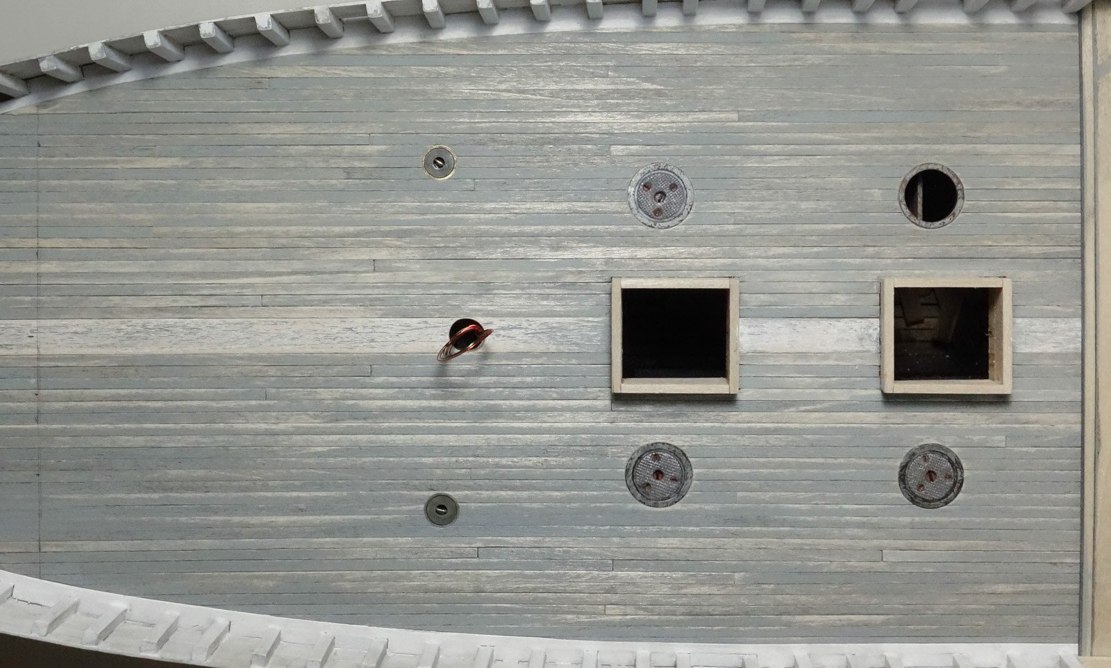
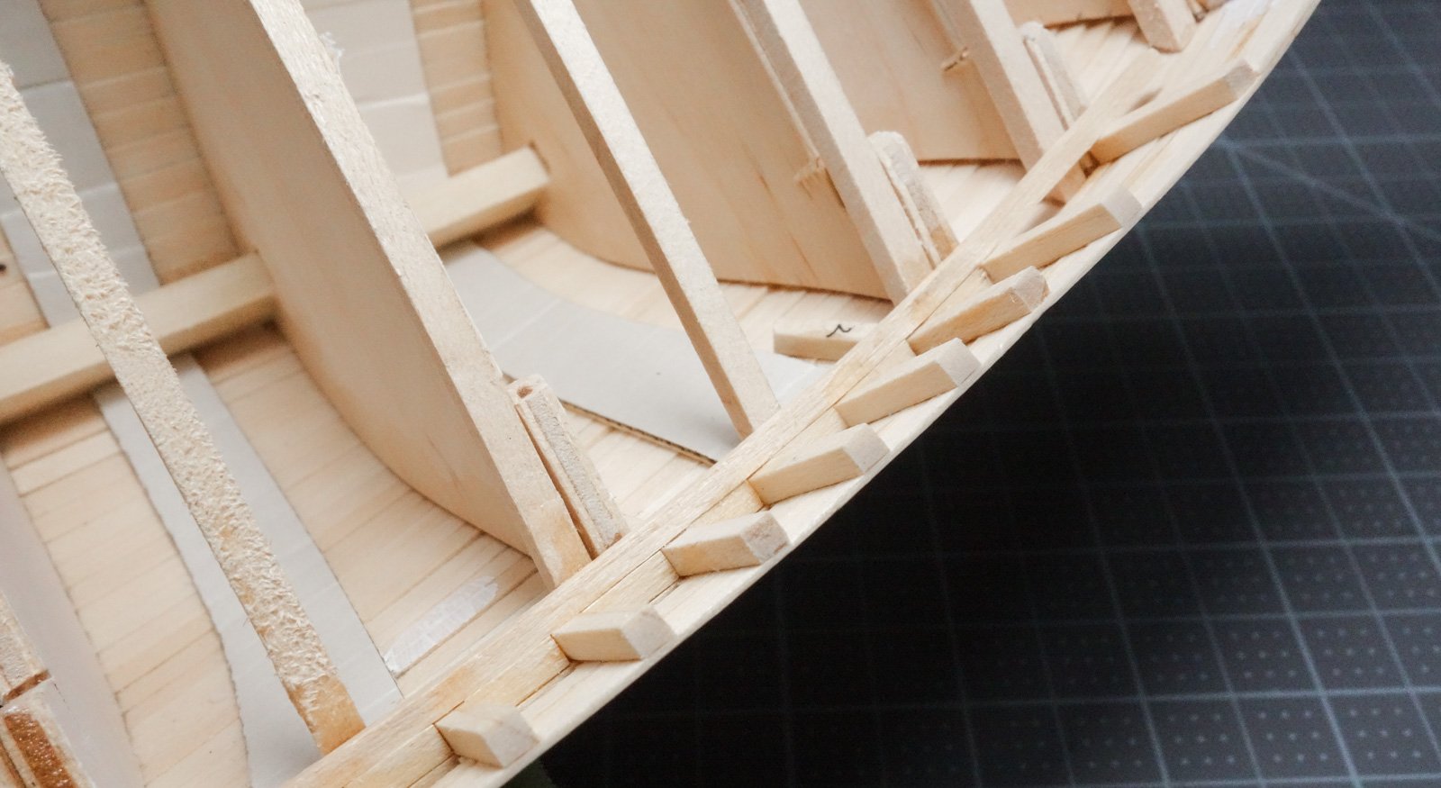
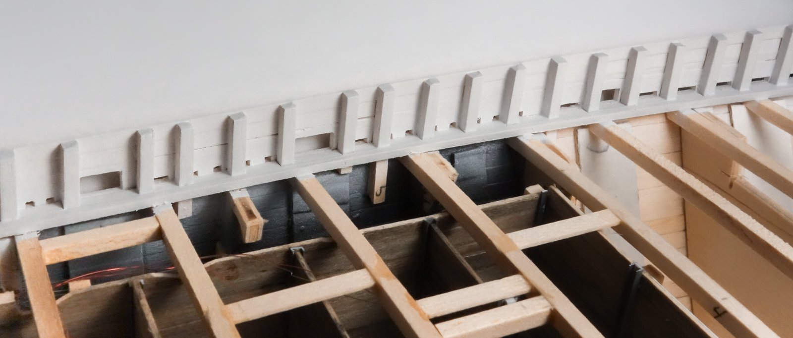
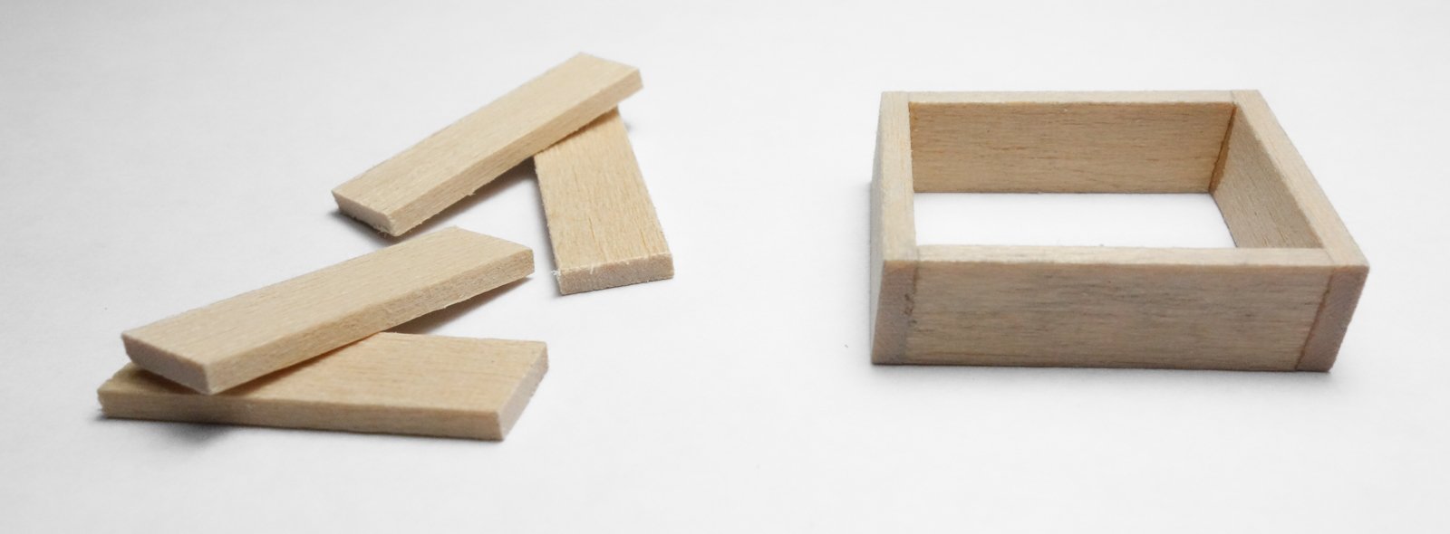
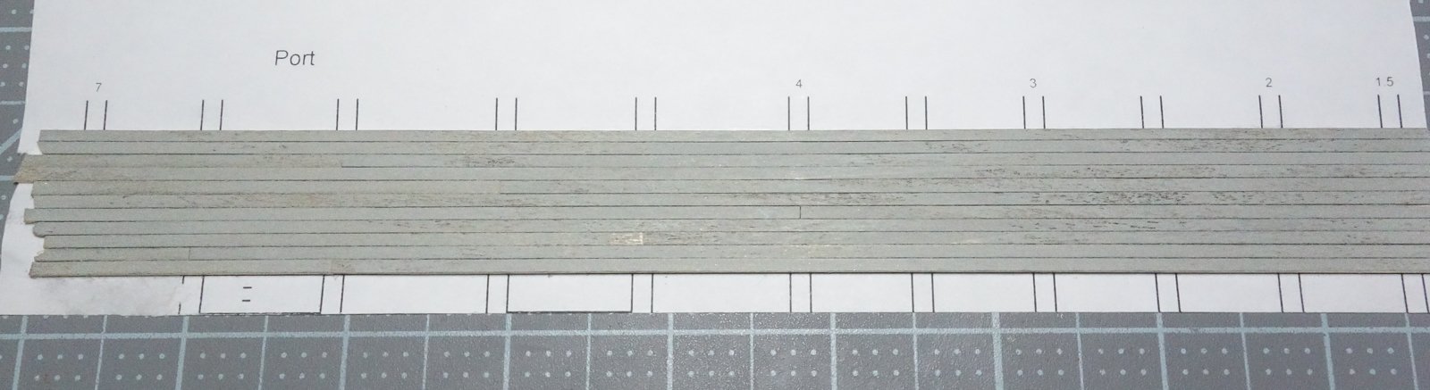
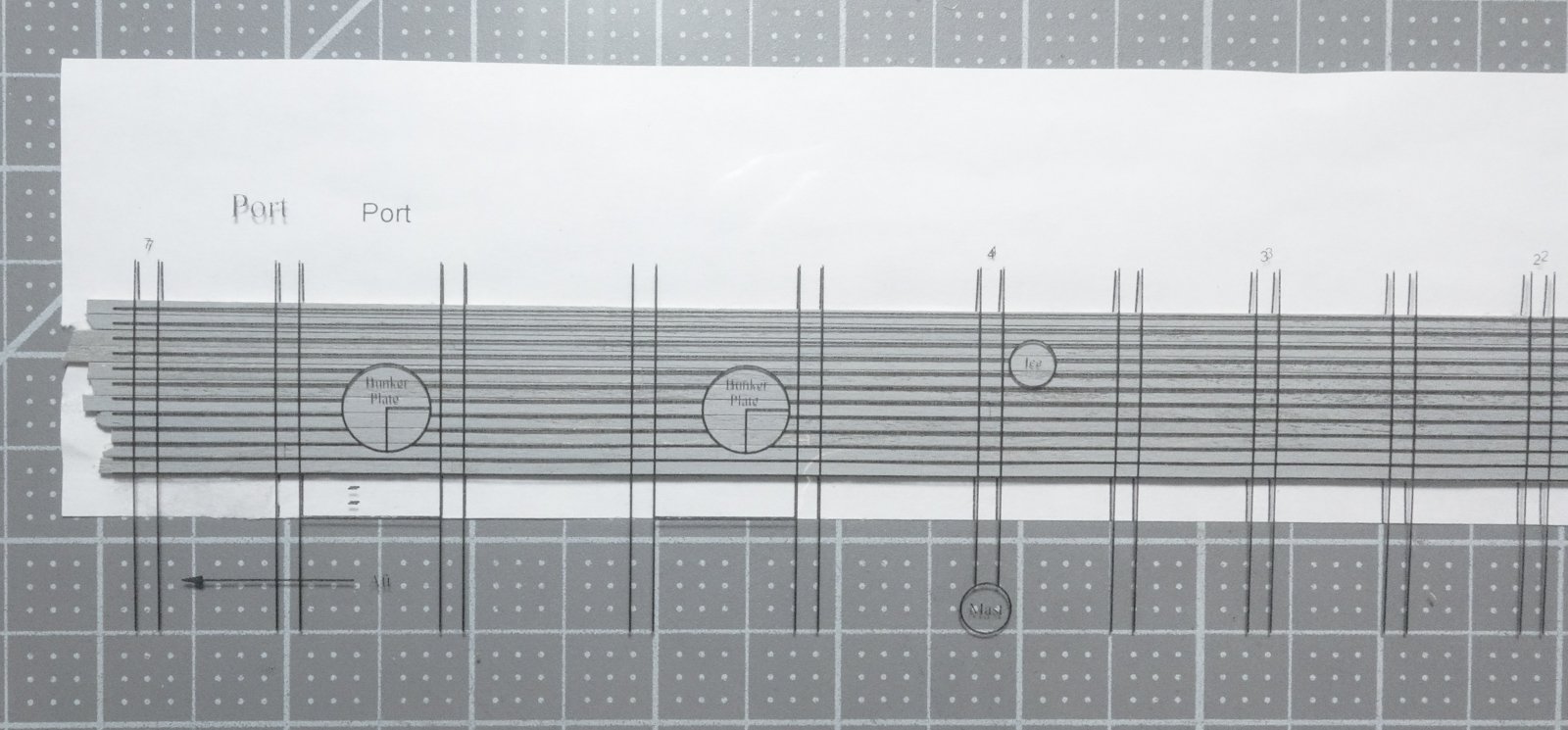
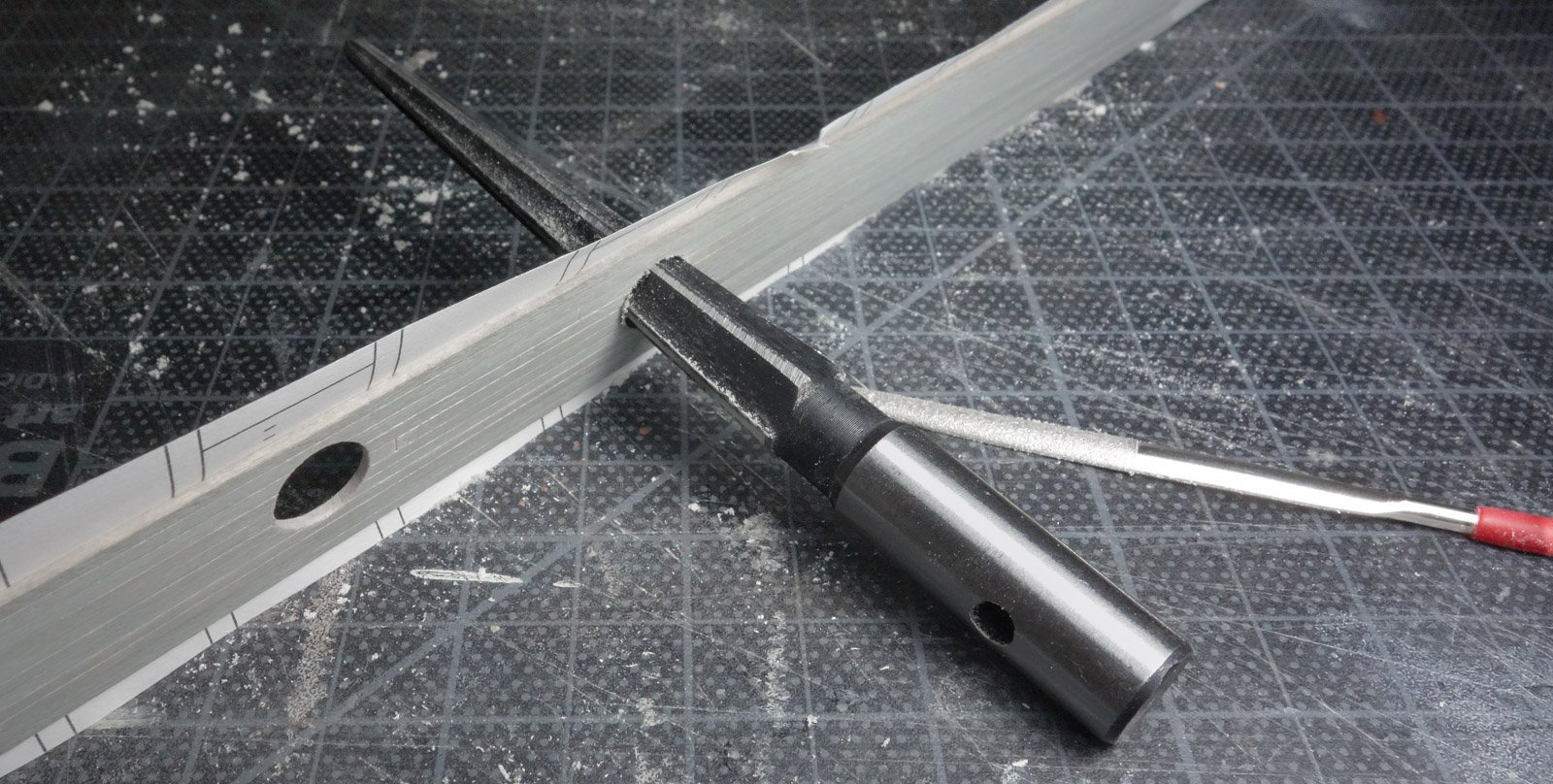
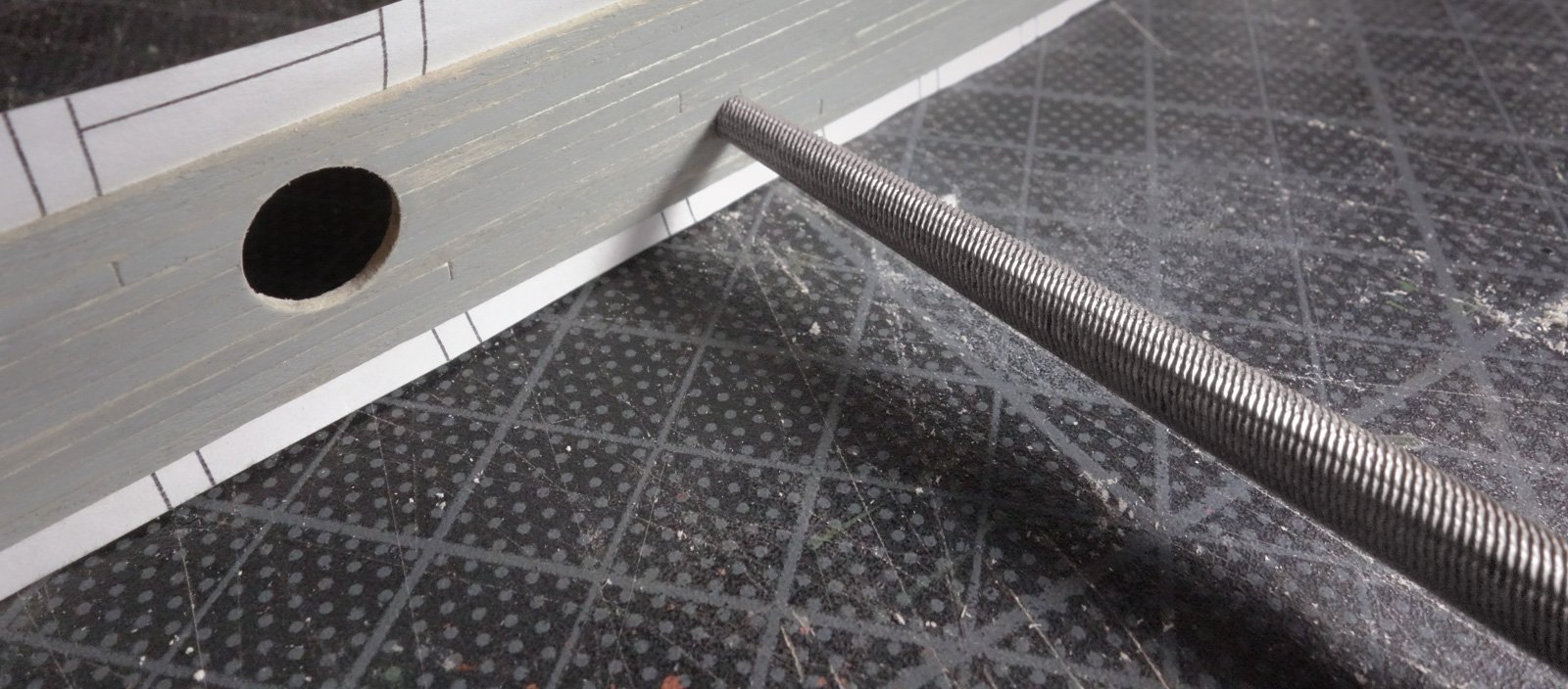
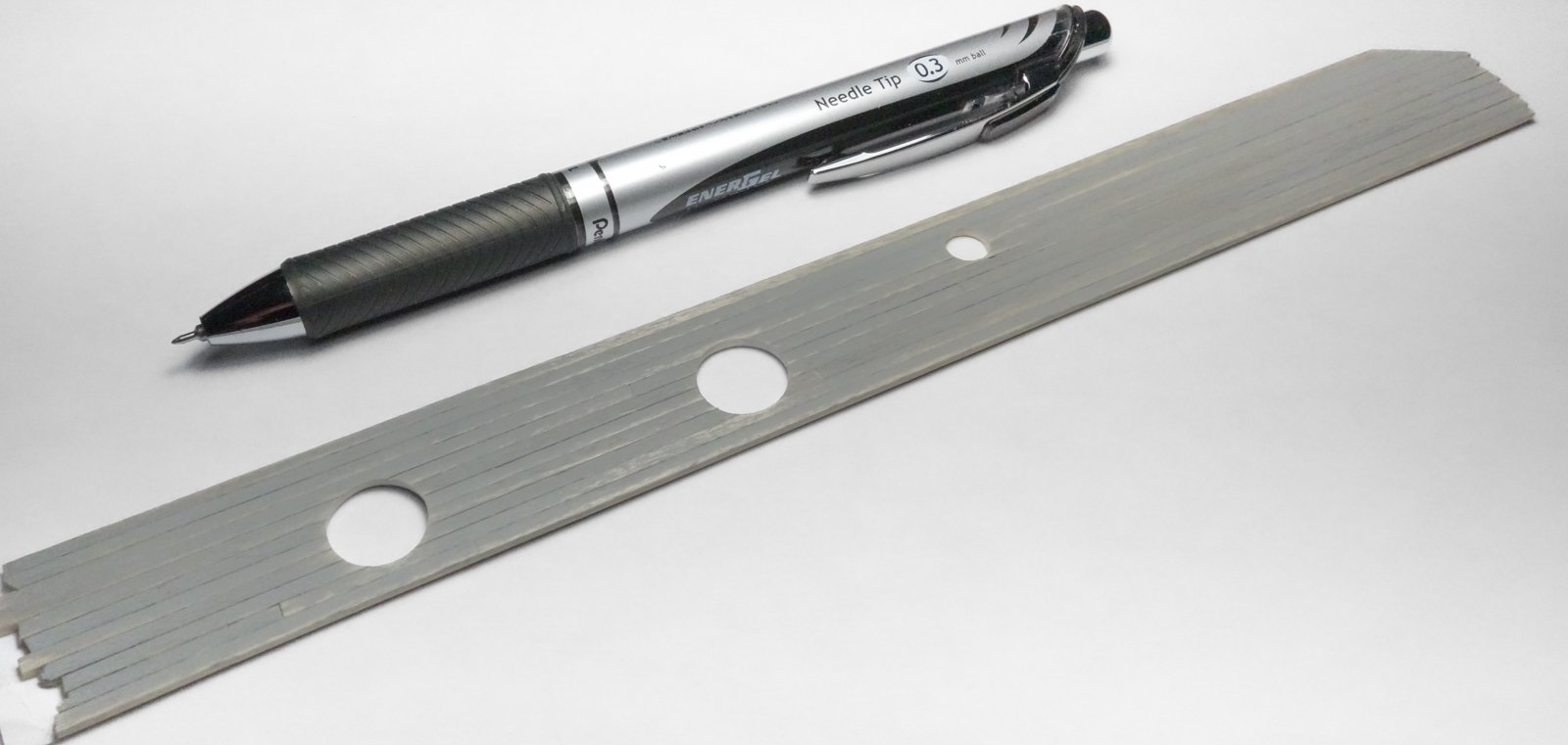
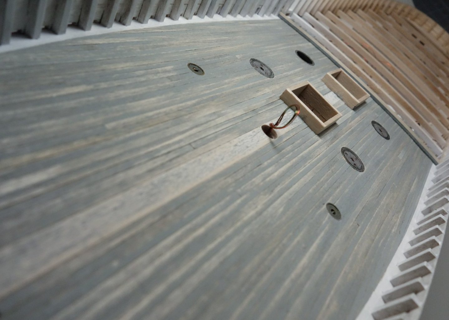
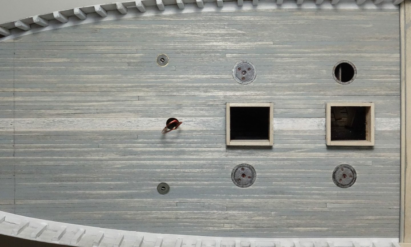
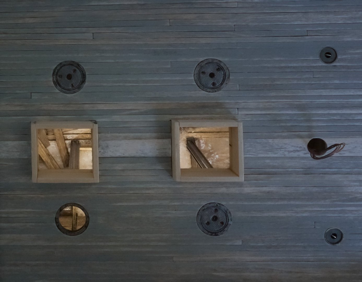
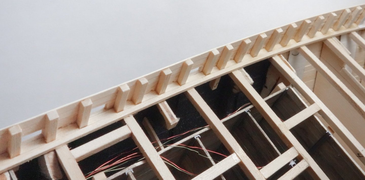
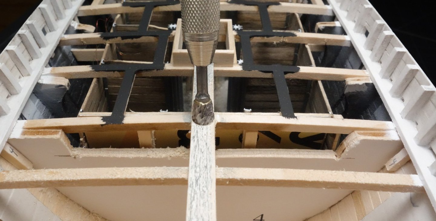
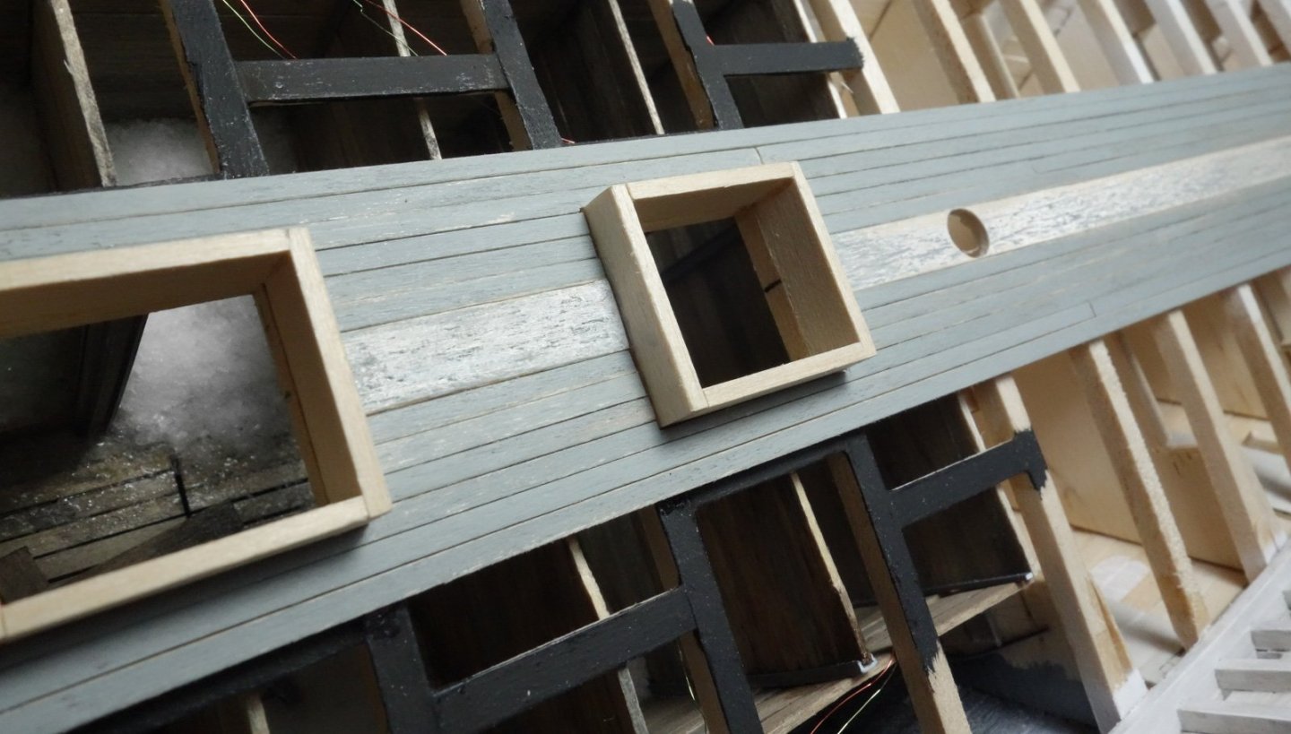
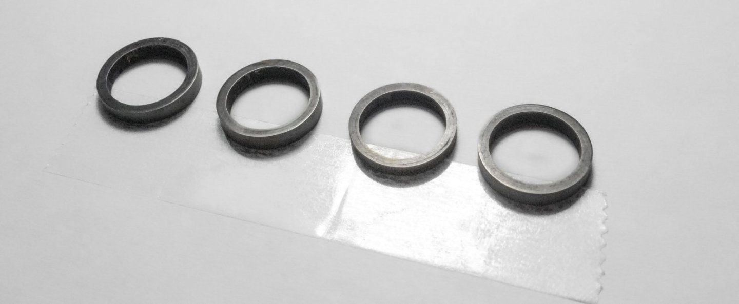
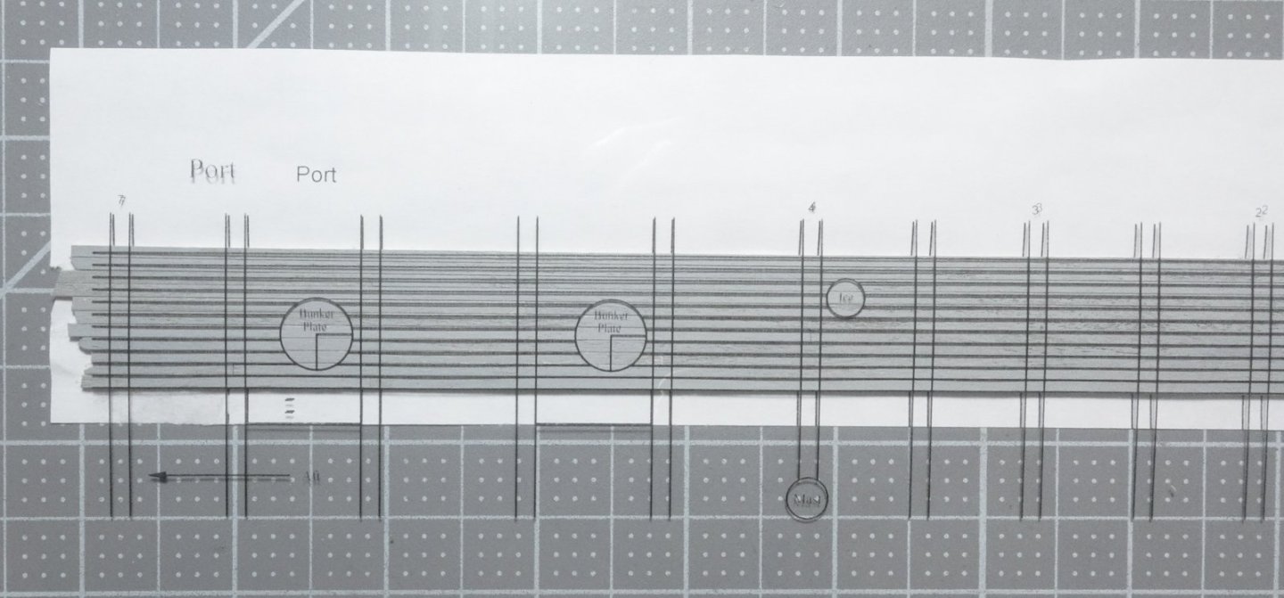
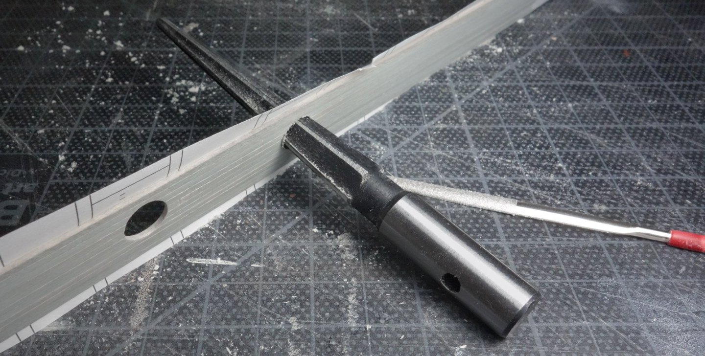
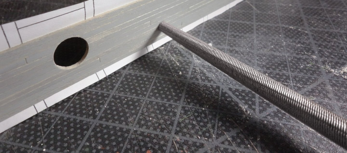
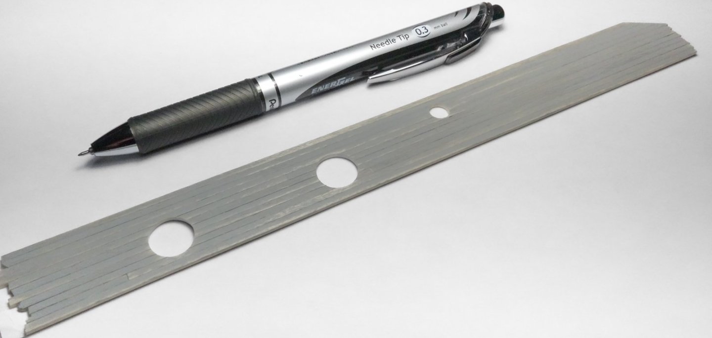
Greetings After several months of doing little on this model, I'm moving forward again. The covering boards have been installed forward of midships. They are pieced together between the top timbers and the inside margin is a single strip. I did it this way because the thick deck planks were difficult to cut crisply around the top timbers. But I would not do it this way again. The top timbers are irregularly spaced in this area to accommodate the freeing ports as per the plans. Airbrushed with thinned Tamiya flat white – 2:1. It looks gray below, but it is white. Later I added a little dirt with pigment powder. Coamings for the fish hold hatches were made from 12” x 3” material. From the side they are parallelograms to compensate for the deck sheer. These are only the lower portions of the coamings, and they will eventually be heightened to 21” above deck. The 12” king plank was placed and a hole for the forward mast was cut. The hole was first pilot drilled then carefully enlarged with a 1/4” burr chucked into a pin vice. The burr cuts too aggressively, so I turned it counterclockwise into the wood. The burr is abrasive enough that even being rotated in the opposite direction still burrows a smooth and perfectly round hole into the soft wood. The plank was painted white on top of gray then scraped with the edge of a safety razor set almost perpendicular to the plank. The deck planks are stained a natural wood color as a base. Then gray paint was scrubbed on top. I added about 10 percent yellow to shift it away from blue. I applied the paint heavier is some areas and practically dry-brushed on in others. I began adding deck planks from the center outward. The planks are 4” wide by 3” thick and were painted black on bottom and sides to help keep the fish hold lighting from escaping. This is not the final deck finish. After all the planking is installed, it will be repaired as needed, scraped, wear patterns added and weathered. This section of deck has four bunker plates and two smaller deck inlet plates. The lids for the bunker plates have already been made and the process that I used is shown back on post #124. They were made from polymer clay and enclosed by a perimeter brass ring. Similar to a manhole cover, these lids fit into ring frames. The frames are made of three slide fit brass tubes that combined provide the wall thickness required. Soldered. Cut from the tube and treated with Jax Flemish Gray. The lids are epoxied into the frames – one will be left open. The deck inlet plates are considerably smaller and have 10” dia. openings. The plans label the port side plate "ice" and is positioned over a walk-in refrigerator. The starboard plate passes coal to a bin in the galley next to the cook stove. The plates are made from brass tube, wire and styrene. I made a section of deck for each side of the boat and cut holes for the deck plates off model. I did this to avoid getting wood chips and sawdust down in the fish hold. I began by creating a positioning template in CAD. I glued planks directly to the template. I could have glued them to a blank sheet of paper, but this insured the edges were straight and the combined width was correct from end to end. I then printed the same drawing on laser transparency and used it to locate the cutouts. The bunker plate holes were drilled through then enlarged with a tapered reamer twisted counterclockwise. The edges were cleaned up with a diamond needle file. With a tapered round file, the same was done for the smaller inlet plates. Plates glued into place. The other side was done the same way. Thanks for looking. Be safe and stay well. Gary


-
Very nice progress, Rob. Hope you're feeling better soon. Gary
-
Very true, Glen. And as a sufferer myself, I was only offering some friendly intervention before it gets out of hand. Gary
- 185 replies
-
- 7
-

-
-
- Flying Dutchman
- Black pearl
- (and 2 more)
-
Very nice progress on Discovery, George. That's most likely about controlling the spread of freshwater Zebra Mussels. They are a destructive invasive species and problematic in many places in North America and indeed other continents. Free swimming larvae often attach themselves to hulls. Gary
-
She's looking really sweet, Paul! I like the base - long and thin like that graceful hull and it doesn't pull attention away from the model. Sort of minimalist. Gary
- 201 replies
-
- 5
-

-
-
- Oyster Sharpie
- first scratch build
- (and 1 more)
-
Such great workmanship, Keith. As others have said, the crew adds motion to the piece. Fantastic job - congratulations! I'm really looking forward to watching you bring Lula to life. Gary
-
Nice progress! Tricky figuring for unfolding the Dutchman. Sails look appropriately tattered - nice. Only a modeler would look at a dryer sheet and say to himself - "hey now, look at this material". You got the disease bad, Glen. Gary
- 185 replies
-
- 10
-
-
-
- Flying Dutchman
- Black pearl
- (and 2 more)
-
Very nice progress, John ! Gary
-
Late to the party, but all caught up. Another ambitious project, Glen - best of luck. I'm confident you'll pull this off and it will turn out crazy cool. Gary
- 185 replies
-
- 7
-
-
-
- Flying Dutchman
- Black pearl
- (and 2 more)
-
Very nice progress, Glen - and the “yard work” is looking great! Nice - does it run on batteries or is it one of those new fangled gravity units? Gary
- 301 replies
-
- 4
-
-
-
- Constitution
- Bluejacket Shipcrafters
- (and 1 more)
-
Excellent work, Paul - the barrel looks great! Gary
- 201 replies
-
- 5
-
-
-
- Oyster Sharpie
- first scratch build
- (and 1 more)
-
Superb little dory, Richard! To my eye that is why your dory sings - because you reproduced the thickness of every member accurately. It is so easy to oversize wood dimensions at this scale, but your boat is true-to-life, delicately made and even elegant. Very nice indeed. Gary
-
Beautiful hull, Keith. Gary
-
Me too - charming. I learned from model railroaders years ago how important a quirky roof structure is to an appealing model because they are most often viewed from a bird's-eye perspective. With Lula's quirky structures, interesting horizontal surface shapes, paddle wheel, staircase, railings, cables, bell, etc. - this floating supply boat has it all and is simply dripping with character! Take your time and enjoy every minute modeling this intriguing little craft. The option Eric offered in the posted photo of the New Era, I feel is a good one. Having the stack positioned at one corner of the pilot house while the ship's wheel is slid over toward the opposite corner seems an interesting possibility. Best of luck on this new project, Keith. Gary
- 732 replies
-
- 5
-
-
-
- Lula
- sternwheeler
- (and 1 more)
-
Catching up after some time away, Keith and what a fantastic looking model you've created! I know I'm repeating myself here, but I really find the overall feel and impression of the model to be very congruous - each element complements the whole and nothing feels or looks like it doesn't belong. A great job of merging disparate components into one, and your very effective weathering reinforces that. Look forward to the final touches. Gary
-
Thanks for the info, Brian. Before retirement, I used AutoCad for decades in electrical design and documentation, but I no longer have access to it. Now I use an older version of DesignCad. But for 3D part creation for printing, I prefer solid modeling over surface modeling, so I've been looking at some of those programs. Gary
-
Very nice, Andrew. Beautiful model - well done. Congratulations on its completion. Gary
-
Good to see an update, Brian - very nice work. I've always wanted a miniature lath and milling machine and if I had those, I would be wearing them out from use. I see them simply as tools to advance one's vision and quality of the model. They provide the freedom to create parts that one might otherwise decide to pass on, because they are either too difficult or next to impossible to create without them. I do enjoy the process of attempting to make parts by "hand", but if I had machine tools there would be a great deal of brass details on my models. I see 3D printing and laser cutting in the same way. Used skillfully, they can enhance and improve the project. If I had these tools, I would use them unapologetically. Though I haven't spent much time creating parts in solid modeling software, I find it isn't slam dunk easy and complex parts take time to create. So, it isn't a free lunch by any means - just a different skill set. I was wondering - did your printer come with solid modeling software or are you using something like FreeCad? Good luck on your foray into this technology, sounds like fun. Gary
-
Spectacular windlass, Valeriy! Nickel plating or maybe silver? Gary