
Supplies of the Ship Modeler's Handbook are running out. Get your copy NOW before they are gone! Click on photo to order.
×

Tigersteve
-
Posts
1,317 -
Joined
-
Last visited
Reputation Activity
-

 Tigersteve reacted to Chuck in HMS Winchelsea - FINISHED - 1764 - by Chuck (1/4" scale)
Work has started on the qgallery framing....
The continuation of the upper counter is of course first. Based on the reference marks from my template, I added the two beams that represent the top and bottom framing. The top frame is 1/8" thick. They are all laser cut for you by the way although a bit longer. The top frame needs to be beveled to sit properly against the transom edge. This image is from the 3/16" scale model and it shows the framing best. You can see the bevels and fairing outboard.
On top of the upper qgallery frame sits a laser cut piece that is very thin. It is just 1/32" x 1/32". But it is curved to follow the inside curve of the frame. This will become important later. You should add this now. Here is what that looks like on the new model. Also note the pie shaped piece that forms the lower frame. This is 1/16" thick. The aft edge is beveled to fit under the edge of the transom. You can see that this lower piece follows the same angle as the top frame.
Once these frames are glued on the outside edges must be faired just like the hull would be. This is in preparation for the planking that will be glued to form the upper counter as it wraps around and forms the qgallery base. The planking is actually just one piece and it has also been laser cut. Again its a bit over-sized because everyone's model will be slightly different. It is 1/32" thick. Once glued on, you can sand the top and bottom edges flush with the framing. (Also the aft edge) The photo below shows it all sanded and completed.
You will have to bevel the forward edge of this shell before you glue it on....this is done so it fits snug and tight against the hull planking.
Finally, you can add the fancy molding that defines the upper counter. These are made from boxwood. They should be 1/8" wide. All of the strips were scraped in their usual way to form the molding. The one thing I would mention which is an exception....the upper molding along the transom is actually 1/16" thick. This is the only one that is thicker. We need it to be thicker so it stands proud of the transom to support all of the columns and carvings between the windows. But I used the same scraper to make this one that I used for the thinner strips.
In addition, I also scraped the fancy molding that is shown on either side of the stern post. These define the bottom edge of the lower counter. It has a slightly different fancy profile but is also 1/8" wide. It finishes off the lower counter quite well and neatens it all up. It separates the hull planking and any messy ends of those planks you might have been less successful with. Just cover the seam slightly to hide any defects.
In the photo above you can also see that I tested the drop in position as well as the figure that sits on the end of the transom. Jack did a great job with these and they fit really well. They look great!!!
If you wanted....you could add the drop permanently at this point but dont add the figure. I was just testing how it fit. In addition I thought I would test how well the friezes fit and what they would look like. These are also NOT glued on yet. They are just lightly tacked on so I could see how they look. I wanted to see the color and shape of these and if they actually fit. I have a bit of tweaking to do on these but I do think they look good. What do you think? They are literally the actual friezes from the contemporary model. They are replicated as best I could.....but are very very close. You can check them out in our gallery on the contemporary model.
-
Tigersteve reacted to DelF in 18th Century Pinnace by Delf - FINISHED - Model Shipways - 1:24 scale - SMALL
Got the first two strakes in, in between garden chores.
Helps to show off the lovely lines of the pinnace. Back to the garden.
Derek
-
Tigersteve reacted to md1400cs in Santisima Trinidad by md1400cs – FINISHED - OcCre - 1/90 - cross-section - bashed
Minor same area update - pics speak for themselves - I am very happy with how the stunt boom yard came out.
I need to check my settings - I'm not getting updates from the builds that I follow - some yes some no hmmmm
-
Tigersteve reacted to Beckmann in HMS Winchelsea by Beckmann 1/48
For getting the notch around the gunports right, I made myself a little "help".
-
Tigersteve reacted to flyer in HMS Bellerophon by flyer - FINISHED - Amati/Victory Models - scale 1:72
Right after posting the last pictures I started to clean up the taffrail a bit, took out the most offending support - and before I knew know - the whole taffrail was taken apart.
Time for version 2.0:
New, shorter supports with 3,5 instead of 5mm height were cut and adjusted to the curvature of the transom edge. Then I glued them with epoxy adhesive because there is quite some stress on them while fixing the rail. The rail itself was sanded thinner, smaller and smoother. Then I carefully drilled small holes through rail and supports into the taffrail for the nails. Even with pre-drilling the nails might split the supports. Now the rail was epoxy glued and nailed onto the supports, all cleaned and painted and voilà - rail mk2.0 looks much more shipshape than the first try.
new rail
the skipper is quite happy with the new rail, however that deck is a disgrace to the ship and must be cleaned
the skipper definitely likes the new look
-
Tigersteve reacted to flyer in HMS Bellerophon by flyer - FINISHED - Amati/Victory Models - scale 1:72
That illogical gap in the rail over the transom looks as strange as a missing front tooth. The well known Bellona model and even the Mamoli model do have a taffrail in this position. On various other models, contemporary and new, you find one as well.
Therefore I tried to include such a taffrail.
First I soaked a 5x1 mm strip of boxwood in warm water and clamped it onto the upper edge of the transom (not without damaging a few details in the process) and let it dry. Boxwood takes such a form quite well and holds it.
Then I put some supports in place and glued and nailed the taffrail onto them. The rail ends are deliberately set onto the same height as the side bulwark tops, not the side rails. After some reworking, sanding and painting and doing the necessary repairs I had a rough rail.
Basically the whole idea worked , but judging by the pictures (which again seem more impartial than the naked eye) the supports aren't vertical, the rail seems a bit too fat, needs some smoothening and maybe still sits to high above the transom. I'll think about reworking it.
In the meantime the rest of the carronades were rigged and the foredeck completed with belfry and rail.
forming the boxwood
rough rail...
...placed on the supports
reworked and painted
taffrail in place and quarter deck armed
fore deck finished
-
Tigersteve reacted to DelF in 18th Century Pinnace by Delf - FINISHED - Model Shipways - 1:24 scale - SMALL
Thanks OC.
Not much progress over the last few days - more time spent in the garden preparing for Winter than in the dockyard. I tried marking the frames but with mixed success. I'm sure I understand the principle, and I printed off a fan and prepared tick strips as per instructions:
I don't know if it is because the frames are very narrow or I'm too cack-handed, but I found it very difficult to hold the tick strip against the frame edge and mark it. I just couldn't mark the frames accurately enough. For example, if I marked two frames that I knew were the same size (when measured from the rabbet to the sheer), the marks didn't line up exactly. In the end I decided that, because the frames were all of a very similar dimension apart from the last 3 or 4 from the bow and stern, I could safely fit the first couple of strakes on each side, and possibly the garboard strakes, then have another go at marking off the remaining gaps.
Taking another tip from Chuck Passaro, I got hold of a cheap travel iron to help with edge bending - works a treat!
To bend strips in the flat dimension I clamped them to a variety of curved surfaces and used a hot air blower to set the shape. I got the first strake on but clearly hadn't curved it enough at the stern:
I wanted to see if I could increase the curve by heating the plank in situ, but wasn't sure which side of the wood it would be best to apply the water and heat to. So I did a couple of quick tests with a scrap piece of strip on the bench.
It didn't seem to matter which side I went, the curve stayed in either way.
I ended up hedging my bets and applying water and hot air to both sides whilst holding the strip tight against the transom. When released there was a marked improvement which should glue up much better.
Meanwhile, back to the garden and my new favourite tool (next to my Byres saw that is) - a petrol shredder that takes branches up to 4".
-
Tigersteve reacted to EdT in Young America 1853 by EdT - FINISHED - extreme clipper
Thank you for these recent comments - Nils, Kortes, Svein Erik, Micheal and Clipperfan. Seems like a while since I have been in touch on the forum since the model was completed in May. Spent quite a bit of time on the third volume this summer and I believe it is soon to be out. For those of you who got the Seawatch ad insert in the last NRG journal issue, the book is featured. In addition to the features listed in the ad there are also 13 printed drawings in 1:96 and 1:72 scale. These were not mentioned in the ad.
Cheers all,
Ed
-
Tigersteve reacted to Chuck in HMS Winchelsea - FINISHED - 1764 - by Chuck (1/4" scale)
Moving right along...
I am about to start framing out the quarter galleries. But before we do that, we must take care of those stern windows on the transom. I am only referring to the one in the quarter gallery that is actually a "dummy" window. This window was actually boarded up in the qgalleries. I am not even sure if it had an actual piece of glass in it. Needless to say I added the laser cut acetate window pane. This is something that just makes the stern look more consistent in my opinion. But you can leave it out if you prefer.
So there are three layers...
First the laser cut window (light).
Then the acetate pane
lastly the laser cut 1/16" insert.
The aft side of this insert should be painted a dark gray. Try and avoid a pitch black. See below.
The three layers are inserted from the forward side. You dont have to glue the window unless you need to move it around for the best fit. Check it from the outboard side to be sure. Dont put any glue on the acetate. Just push it against the window and let it site there. What you want to do is just apply a little glue to the edges of the insert and add that last. It will hold in your window. Then sand the surface so the forward side of the qgallery is all flush and neat.
With this all done, we can start constructing the quarter galleries. This is some real tricky business. There are so many angles to contend with. You must establish the correct slope of the qgalleries. This is the hardest part. We will be constructing the "stool" of the gallery first. This is the extension of the upper counter as it wraps around to form the base of the qgallery.
But you just can begin by grabbing the laser cut framing and and gluing it onto the model. The angle of the stool is crucial to every additional laser cut part for these galleries. If the angle is off, none of the windows will fit etc. So measure twice and then measure again.
To assist with this, I have created some paper templates for you. This is nothing new. Many of you have used this technique before.....see below.
BUT....I have seen many of you make a crucial error when using them. You dont want to place these against the hull planking. This will result in your quarter gallery having the wrong angle and NOT following the run along the hull you want. Instead, you need to cut the template out carefully and tape it to the outside edge of the transom. Get this against the transom neatly. In fact you will notice that is is just a hair lower than the bottom of the transom. This is because if you follow the bottom edge of the template aft, it will intersect with the aft edge of the transom. This is important and I hope that makes sense.
The 1/8" band on the bottom of this template represents the top of the stool framing. You need to mark the forward edge of the template with a sharp pencil....the whole edge.....
Also mark the aft side which will reference the top of the qgallery along the transom edge. The top left of the template.
When you pull the template off, it will look like this below.
Well actually you will just have the forward pencil line. Then you need to add another about 3/64" aft of it. This represents the shell thickness of the qgallery. Also note how I defined the 1/8" frame at the bottom. This will be the first qgallery timber we add to the model. That will be shown in my next post.....
This is some complex stuff with all of these angles, so please feel free to ask me any questions. ....
-
Tigersteve reacted to Ondras71 in Roter Löwe 1597 by Ondras71
Thank you very much stuglo!!
I was stopped by the warranty repair of the lathe proxxon, a little woodwork. Gun Port covers ..
Side test..
-
Tigersteve reacted to ClipperFan in Young America 1853 by EdT - FINISHED - extreme clipper
Hi Ed,
It was my distinct honor and pleasure to meet you when your incredible twin hulls of the Young America were on display at Mystic, CT in the Fall of 2016. It was hard to keep my jaw from hitting the floor, even back then when masting and rigging was just beginning. What you have created is a Clipper Ship in Miniature. I'm fully convinced, were it possible to enlarge this artisan craftsman, once the balance of strakes had been laid on to make her 'sea worthy' your miniature vessel would look and perform identically to her original! To say well done just doesn't do justice to what you have accomplished.
FYI: I love your artist impression. No need to apologize to us mere mortals!
-
Tigersteve reacted to mahjong25 in 18th Century Longboat by mahjong25 - FINISHED - Model Shipways - 1:48
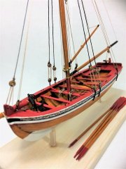
Continued to rig my ship with some addition. I am really excited being on the last page of the instructions. But I ran out of rope so I'm waiting for the new order to come in to finish up. Now just need to look for a good display case!
-
Tigersteve reacted to CRI-CRI in USS Confederacy 1778 by CRI-CRI - FINISHED - Model Shipways - scale 1/64
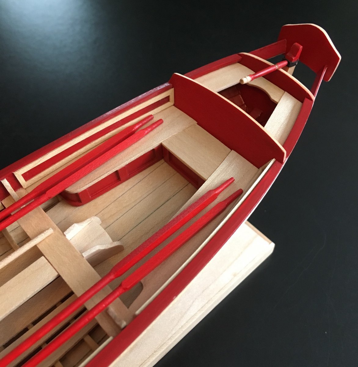
Longboat's floorboards assembled after paper template (not glued)....
-
Tigersteve reacted to JSGerson in USS Constitution by JSGerson - Model Shipways Kit No. MS2040
It’s been about a month since my last post; I have had some highs and lows in that time. I’m still struggling with my left eye although I got the remainder of the stiches removed today– four in total. It’s slowly improving but up till today, I was just using my right eye. Now there is a marked improvement. We’ll “see” what the Doc says in two weeks.
I made the effort to go to the NRG Conference in New Bedford MA (Oct 23-27), where I met old friends and generally had a good time despite some travel headaches, but that’s another story.
However, on Nov 2, my Mom died at 101yrs. It was not unexpected but still it was a shock when it happened. My time was spent with my family and doing the things that needed to be done when there is a death in the family.
Weeks later, things are slowly getting back to normal, but there are things that still need to be done, Thanksgiving is coming, and I’ll be with my sister for the holiday week. On the bright side I was able to get my mind on an even keel as it were, by working on the model. It puts my mind at ease. I was able plank the remainder of the hull between the side spar deck gun ports.
You may also notice that I have trimmed the bulkhead extensions that stick up above where the cap rail will go. They extended to support the Topgallant Rail. This was the “Cap Rail” of the added hull and bulwarks on top of the actual Cap Rail. This extension was added in 1926 and subsequently removed in later restorations. Since my model is trying to reflect what the ship looks like today, it will not be built as shown in the kit plans which is based on the 1926 restoration.
-
Tigersteve reacted to SardonicMeow in Sultana by SardonicMeow - FINISHED - Model Shipways - Scale 1:64
The aft rails are next. Below is a picture of the Sultana with the rail stanchions marked. Middle stanchions are in pairs, and there are singles at each end. (At least, that's what I assumed. The foremost may also be a pair, but I couldn't see it clearly in any pictures, and I went with a single.)
I created the shape of the rail in Fusion 360 to match the curve of the edge of the deck. All rails here and in future steps will be 3.2mm wide and 1mm thick, to mimic 1/8" x 1/32" strip wood.
I made a copy of the rail and positioned the rails in approximately the angle they would appear on the ship.
The stanchions were added. Stanchions are 2mm square at the base, tapering to 1.5mm at the top. Stanchions are taller forward and shorter aft to match the angle between the rails.
The upper rail was moved slightly aft, then square holes were added to accept the tops of the stanchions.
Here are the 3D printed parts. The set above are being glued together. The set below are fresh out of the printer.
And finally the rails were glued to the ship. The rails were painted with black to remove the glossy plastic finish. I also made some short rails for the next step down. These are also visible in the picture.
-
Tigersteve reacted to SardonicMeow in Sultana by SardonicMeow - FINISHED - Model Shipways - Scale 1:64
With the warm months just a memory, I'm back to working on the Sultana.
There are several parts that I'm anxious about on this model. The cap rail over the transom is one. I tried to bend a wood strip for the part, but had little success. So I have tried to produce it via 3D print instead. Modeling it in Fusion 360 was also a challenge, and I ended up with something of a compromise, as can be seen below.
I started with the curve of the transom shape that I had developed previously for the laser cut transom pieces. I thickened the curve to a thickness of 1.5mm.
Then I wanted to extrude it horizontally. But when I tried to extrude I realized that it could only be extruded normal to the plane of the sketch.
That wasn't what I wanted. It turns out that the Sweep, rather than the Extrude, operation was the correct one. I added a line in the direction and length (10mm) that I wanted.
With that, the Sweep operation created the shape.
Below on the left is a picture of the piece as it came out of my 3D printer. I intentionally created a piece longer than necessary, with the intention of filing it down to the correct fit. In the picture at the right is the final piece after being filed down.
And the piece was finally glued into place. I created the small curved fashion pieces in wood, painted black, which merge the cap rail and wales.
-
Tigersteve reacted to Dowmer in HMS Winchelsea 1764 by Stuntflyer (Mike) - FINISHED - 1/4" scale
Joe, one of the things I’ve found that helps me with “cutting” moldings is if you are scraping a 1/16” molding to cut a 1/16” slot into the scraper first. That will channel the strip consistently, then cut the profile into the bottom of the slot. The depth of the slot you cut obviously controls the depth of the profile. I hope that helps.
I typically use an Exacto blade for the scraper. I can then fit it into a handle to use. For cutting I use a thin abrasive cutting wheel in the Dremel then finish with fine Swiss files if needed. There are many ways of accomplishing the task, this is the one that works for me.
Here’s a pic of one I used many years ago.
-
 Tigersteve got a reaction from Tom E in Mayflower by Tigersteve - Model Shipways
Back to planking the remainder of the hull in basswood since this will be painted. Almost done with the first belt on the port side. I anticipate many rounds of sanding and filler. Not obsessing over this part of the planking, as I’m fairly sure I can get a nice surface for painting. A drop plank was created at the bow, which I may show in a later post.
Nothing worth photographing at this point, but here’s a photo of some plank bending.
Steve
-
 Tigersteve got a reaction from JpR62 in Mayflower by Tigersteve - Model Shipways
Back to planking the remainder of the hull in basswood since this will be painted. Almost done with the first belt on the port side. I anticipate many rounds of sanding and filler. Not obsessing over this part of the planking, as I’m fairly sure I can get a nice surface for painting. A drop plank was created at the bow, which I may show in a later post.
Nothing worth photographing at this point, but here’s a photo of some plank bending.
Steve
-
 Tigersteve got a reaction from Blue Ensign in Mayflower by Tigersteve - Model Shipways
Now that the initial phase of hull planking is almost complete, I thought it would be useful to share the method I’ve been using to plank around this tricky bow.
1. Measure 80% of the 1/8” plank width and mark at the tip of the plank. It’s .1”. I use digital calipers for this. Mark 3” from the edge of the plank and draw a line from this point to mark the taper. I sand up to this line by running the plank across a 220 grit sanding block.
2. Bevel the plank to fit against the previously laid plank on the hull.
3. Soak the plank in hot water for 5-10 minutes. (This is the only time I use water.)
4. Clamp the plank to the hull and heat the plank until it’s dry. Let it cool.
5. Mark the butt joint and sand. Test fit on the hull.
6. When you have a nice fit, mark the edge of the plank to simulate caulking.
7. Apply glue and re-clamp.
For the hot water I use a Keurig. I keep a disposable coffee cup in my work area. This works well since the plank lengths at the bow are short. I’ve included a photo of the clamping.
Steve
-
 Tigersteve got a reaction from GrandpaPhil in Mayflower by Tigersteve - Model Shipways
Back to planking the remainder of the hull in basswood since this will be painted. Almost done with the first belt on the port side. I anticipate many rounds of sanding and filler. Not obsessing over this part of the planking, as I’m fairly sure I can get a nice surface for painting. A drop plank was created at the bow, which I may show in a later post.
Nothing worth photographing at this point, but here’s a photo of some plank bending.
Steve
-
Tigersteve reacted to rwiederrich in Great Republic 1853 by rwiederrich - FINISHED - four masted extreme clipper
Next I began work on the top mizzen top mast and royal haul purchases and running them to the crab winches..
-
Tigersteve reacted to Chuck in HMS Winchelsea - FINISHED - 1764 - by Chuck (1/4" scale)
Today I cut a test set of laser cut windows for the stern. They fit perfectly. If you remember on my smaller version, I used laserboard for these. But on this 1/4" scale Winnie, I was able to cut them from .025 boxwood. They are still very fragile but they work great. Now the inside edges do have laser char on them as you might expect. DO NOT try and sand this stuff off. The frames are too fragile for that. If you want to lighten them up on the edges use some weathering powder instead. But be careful. Anyway, these wont be used just yet but I am always making parts before I need them. Thought I would show you guys what it looks like. I tried to make sure they didnt look too heavy while still being not so fragile. The appearance of scale is so important. All of this laser cut stuff will be available in the chapter three installment.
Chuck
-
Tigersteve reacted to Mike Y in Beavers Prize 1777 by Mike Y - 1:48 - POF - Hahn style
Construction progress is not so fast, for a good reason - we got a second daughter a month ago (yay!). Everything goes well so far, we are a lucky parents and Daria (the youngest) helps us a lot. But, as expected, there is little time for anything... Though I still sneak a plank every now and then, so it is moving with a pace faster than zero, one streak per week on average! Each plank takes from 1hr (for a simple straight planks midship) to 2-3hrs (curved ones with difficult shapes). Sometimes a plank goes to waste, so overall it is not a fast process.
It is a nice to get a bit of your own time and work on a model, even late at night. Makes for a good photos
Back to the build progress. Got quite comfortable with heat bending, pretty low error rate. But I still feel that the plank made this way is more brittle than the one shaped with steam. Luckily it is not a big issue.
Since I did a bad job in fairing, there are some low spots that are fixed by adding a filler underneath the plank:
Or chiseling away the high spots:
Slow but steady, I passed the equator - 7 streaks done (plus limber streak), 6 remaining!
Nothing is sanded yet, and considering bad fairing I expect to spend a lot of time scraping and sanding to make the planks look smooth and fair. There are a lot of glue traces, they would be cleaned up after treenailing.
I'm glad I started with internal planking - it is a good training exercise, that would be barely visible on a finished model, hidden under all decks and cabins. Hope to get enough skill to do a better job on external planking Consider this a practice piece.
-
Tigersteve reacted to Forlani daniel in Chebece 1750 by Forlani daniel - FINISHED - 1:48
Good morning and thanks to everyone, more photos.
Un Saluto