Hubac's Historian
-
Posts
3,317 -
Joined
-
Last visited
Content Type
Profiles
Forums
Gallery
Events
Everything posted by Hubac's Historian
-
 Thank you, Druxey! I really wanted to explore a less pristine model, for a change, and now I feel liberated by the discovery of just how easy it is. And it is really helpful to be able to paint spare parts, in order to get a really good idea of what things are going to look like, without sweating the application too much. I cut in the wales on one of the sample pieces, and though I worked pretty quickly, the top edge was a pretty clean line. Nevertheless, even tiny blurps onto the flat between wales can quickly spoil the effect. On the next sample piece, I’ll pull those strokes a little more slowly and deliberately, and see how that goes. But I’ll also try masking with this FROG tape that Dan has had success with. Maybe cut in the mask with a knife, burnish with a Q-tip as another poster cleverly noted on Dan’s Leviathan log, brush on a clear seal coat (Dullcoat) along the tape seam, and then brush in the black. I will prolly have a go at that later tonight.
- 2,699 replies
-
- 2
-

-
- heller
- soleil royal
- (and 9 more)
-
Thank you very much Dan and Henry! Hopefully, it won’t take as long to paint as it did to make. But, we’ll see. And, really, if it weren’t for your donating your old kit parts, Henry, this build would not be possible. The stern extensions buy me the extra real estate I need for the frieze and the new quarter galleries.
- 2,699 replies
-
- 1
-
-
- heller
- soleil royal
- (and 9 more)
-
I wonder what Jimmy Hendrix would have thought of that, if he could see it through his purple haze periscope. What a learning experience, and effort well expended. The dazzle really came out beautifully. Interesting period pics, as well. It really is confusing to make out the shape of the bow on that pic of the ship in port.
- 238 replies
-
- 4
-
-
- leviathan
- troop ship
- (and 2 more)
-
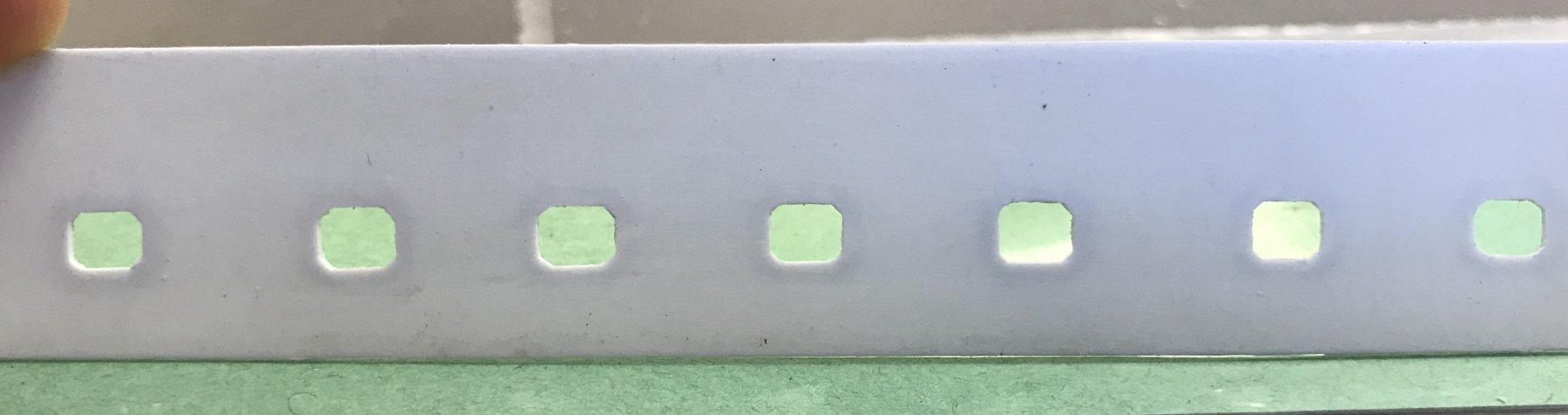
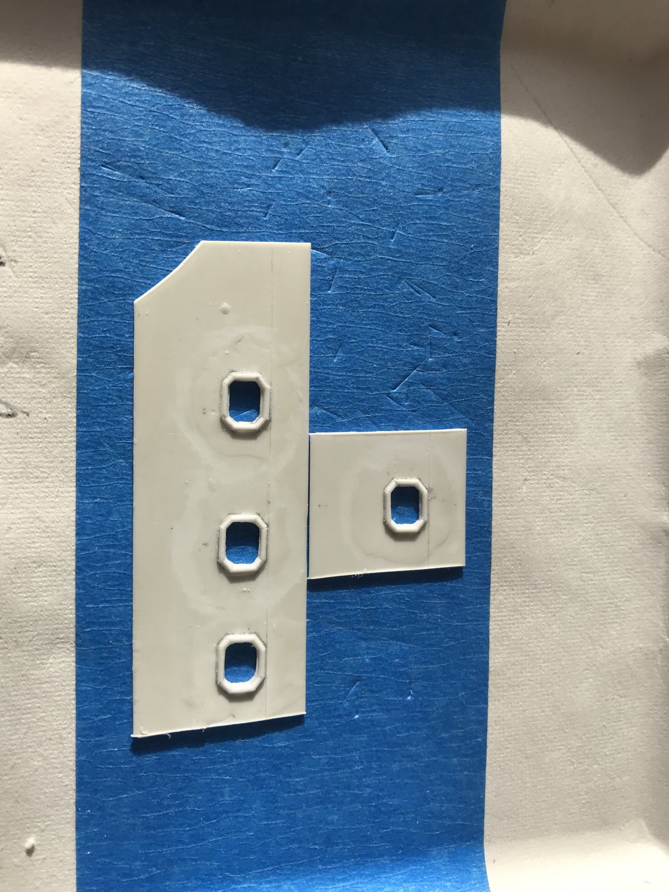
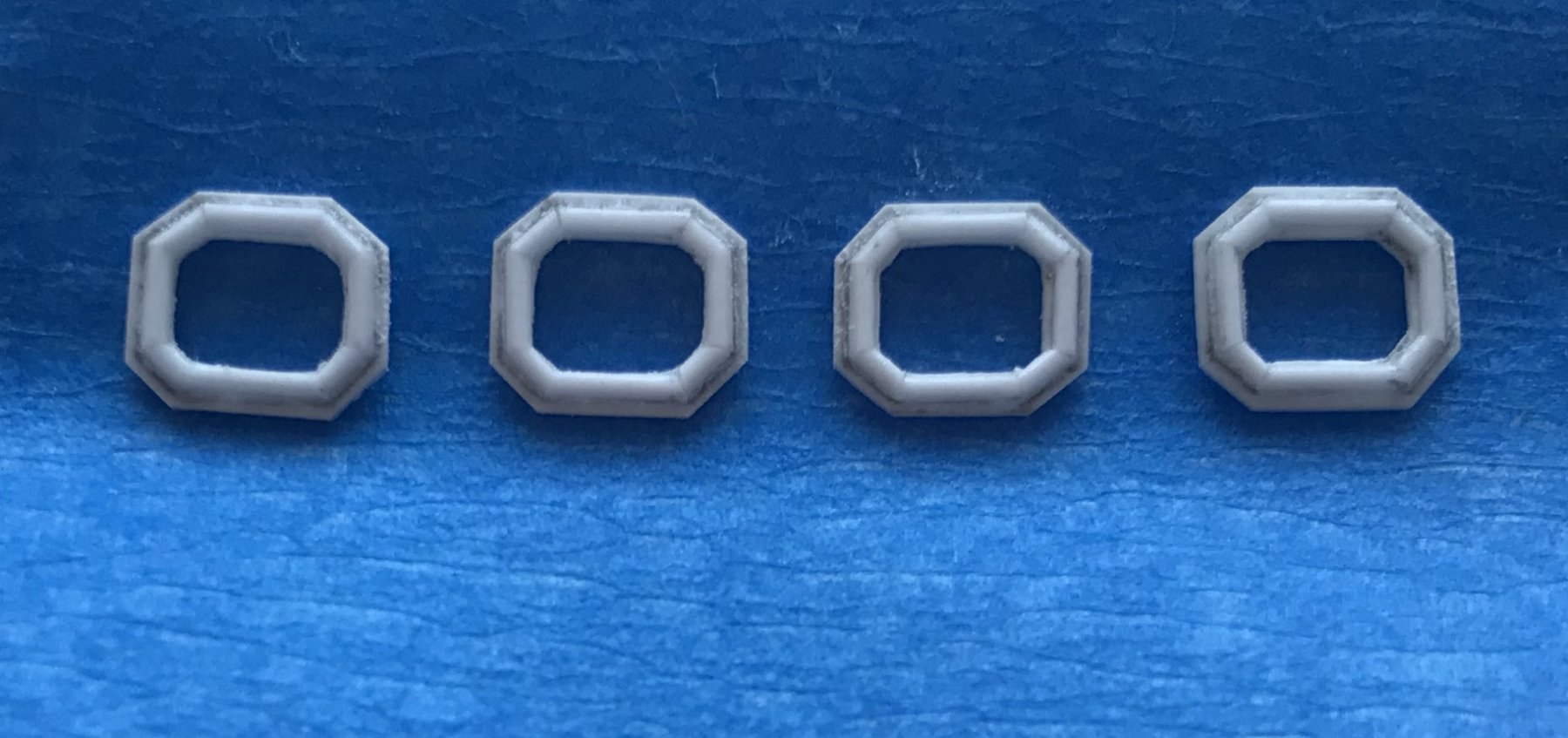
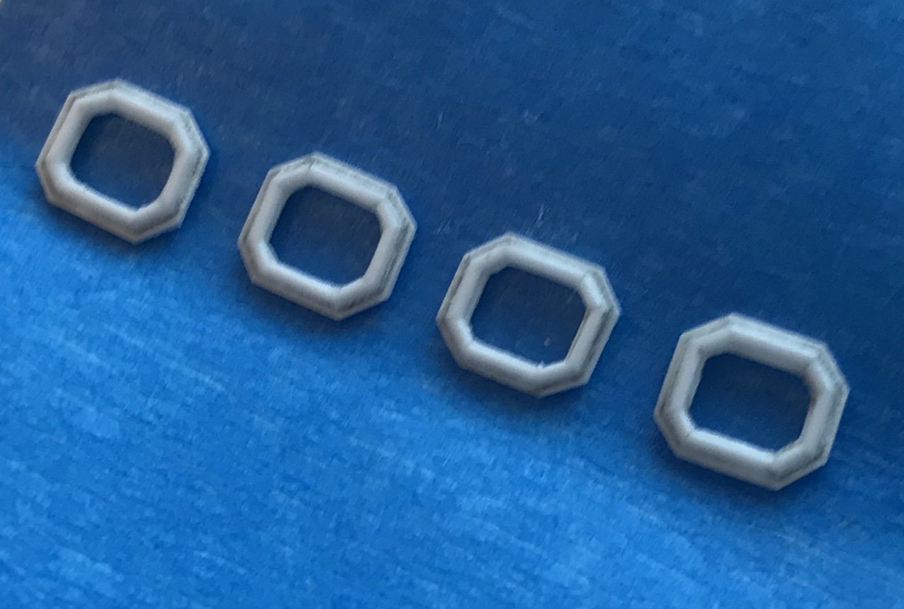
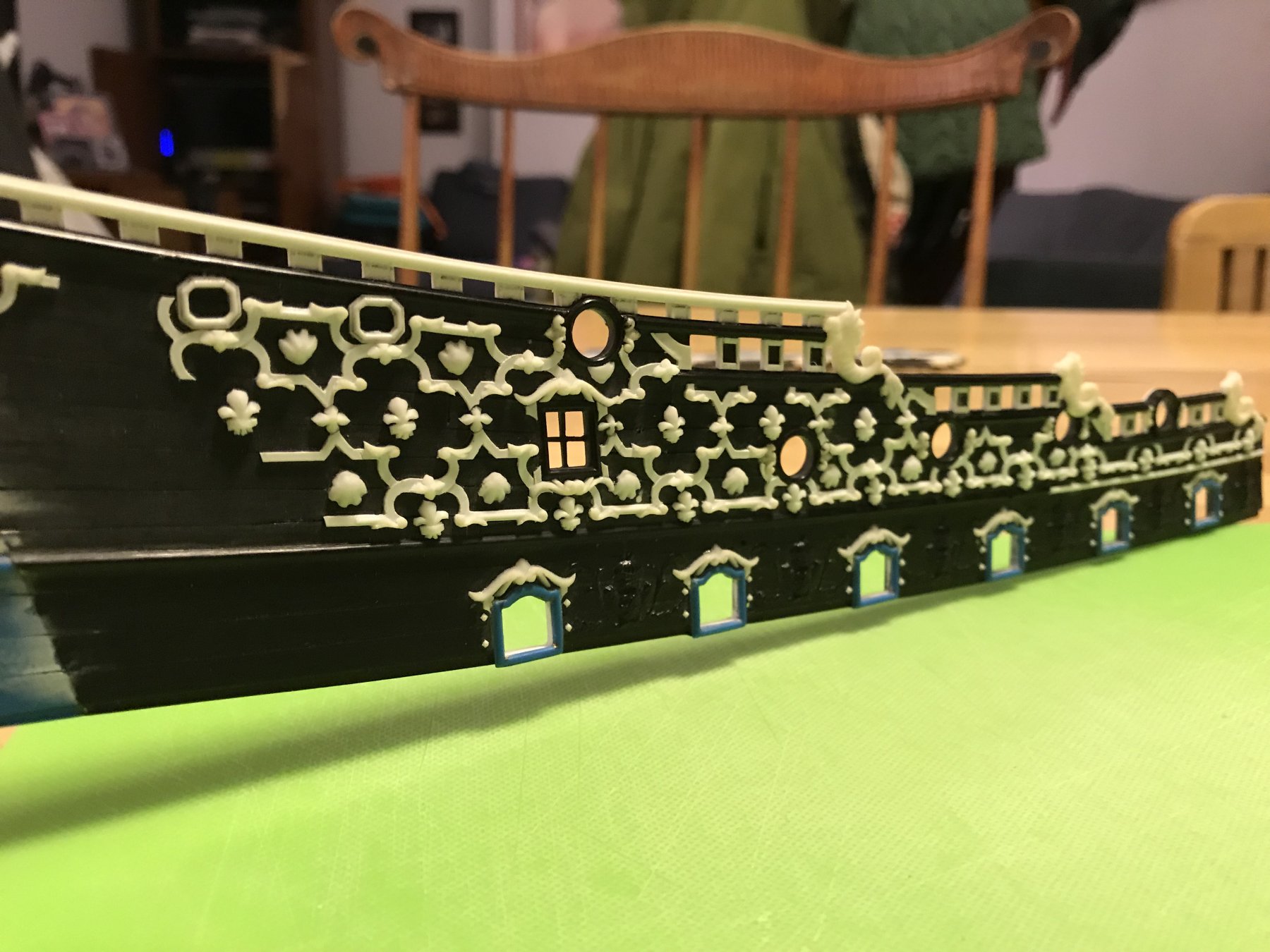
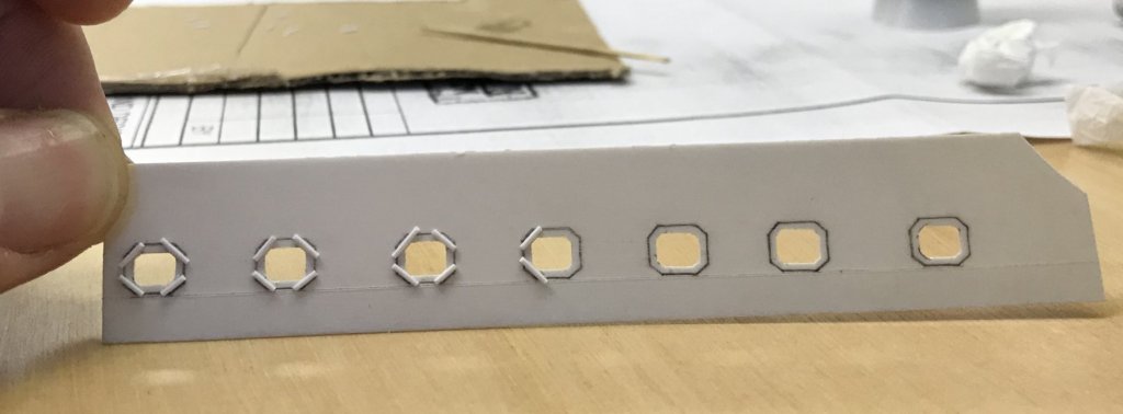
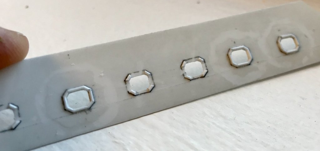
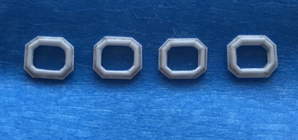
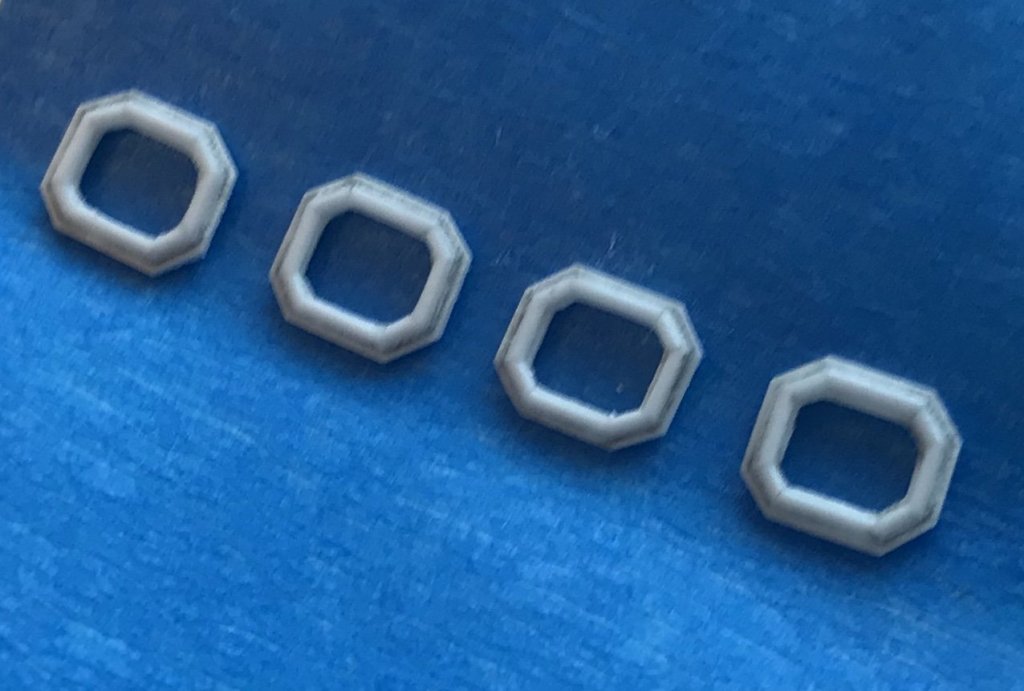
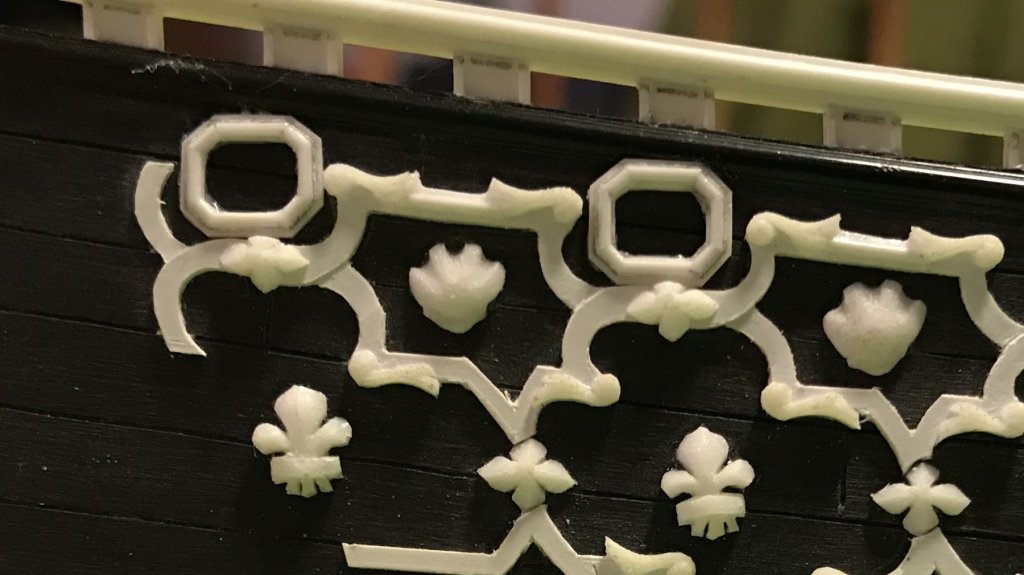
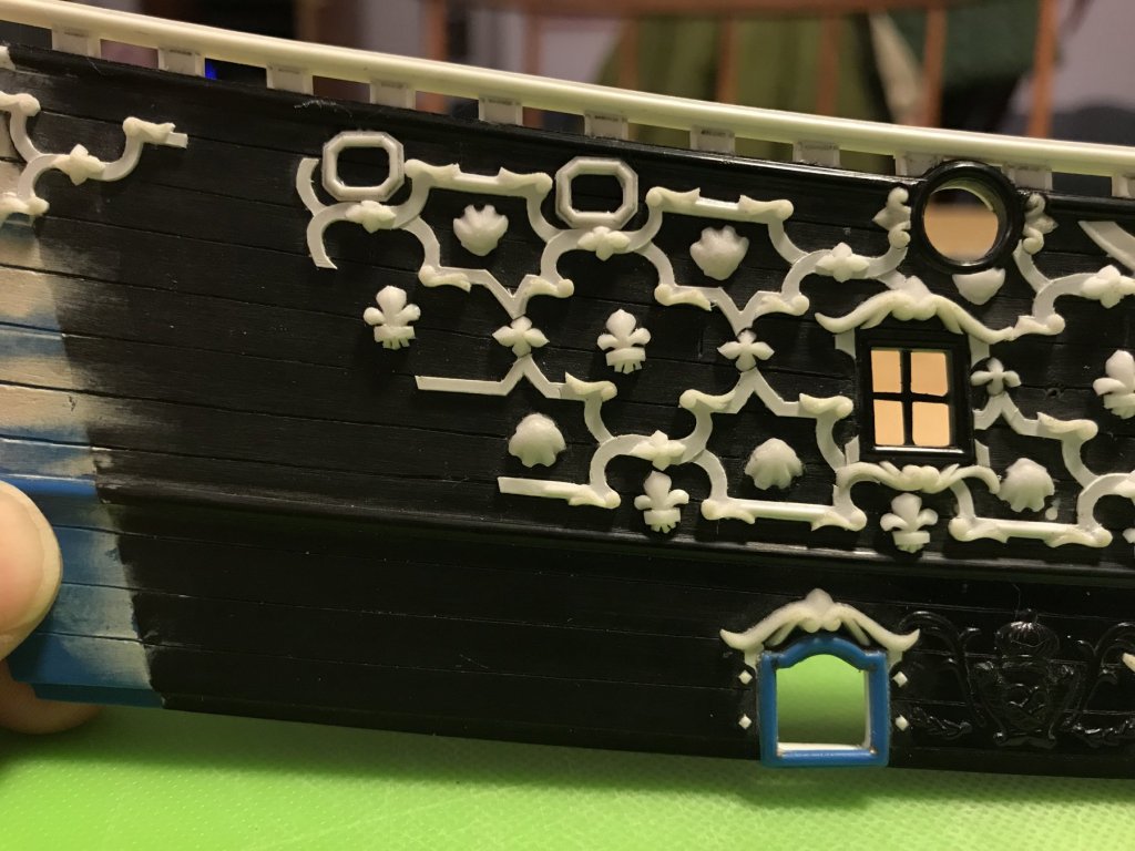
I am usually overly verbose, but this time I will let the pictures do most of the talking. Following are a series of pictures for the cabin windows beneath the poop-royal deck. I tried several approaches - at first attempting to cut a loose framework of half-round moulding that I would assemble directly onto the bulwark pieces. I scrapped this plan because I found it extremely difficult to reliably cut 22.5 degree angles every time on such tiny stock. Instead, it was much easier to cut a tracing template for a backing plate onto which I could glue thinner segments of styrene rod, which I sanded a back facet onto the extrusion, with an emory board, before cutting my moulding segments. It was fiddly work, but the joints are actually tight and cyano filled any remaining discrepancies. It proved easiest to cut oversize segments, at the corners, and then miter them back to the corners of the back plate with a chisel. I made more openings than I needed, and it took some doing to create these tiny little facets into the inside corners. The halo effect around the frames is the coat of cyano that I brushed over each assembled frame, but then scraped into the corners, around the perimeter, with a chisel. If you don’t scrape into the corner, the buildup of cyano will prevent a crisp demarcation of the moulding after paint is applied. For now, I will hold off on actually piercing these openings. While I like their scale (relative to the nearest round gunport) and placement within the frieze, their location would technically interfere with the placement of the poop-royal deck beams and beam clamp. I may decide to ignore this fact and simply represent some form of glazing on the ship exterior, or I may decide to shorten the poop-royal deck so that it begins aft of these ports. The ports would then become auxilliary gun ports. In either case, I will set these parts aside, for now, so I can focus on painting and assembling the lower hull. Later in the project, when I’m feeling more refreshed and confident, I’ll pierce for the QG openings and figure out what to do with the amortisement and all of the accompanying figures. Damn - still verbose!


- 2,699 replies
-
- 9
-
-
- heller
- soleil royal
- (and 9 more)
-
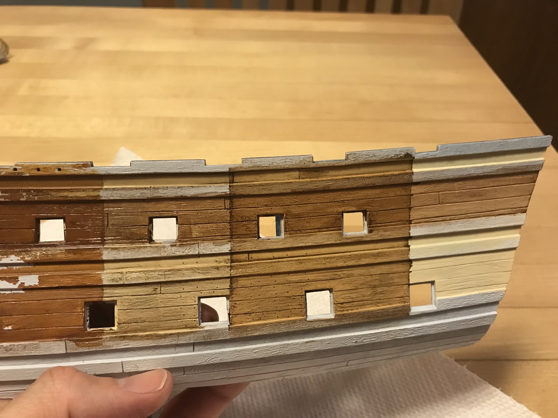
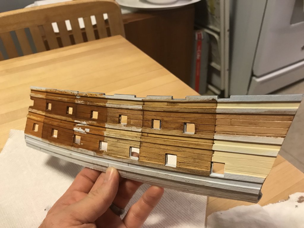
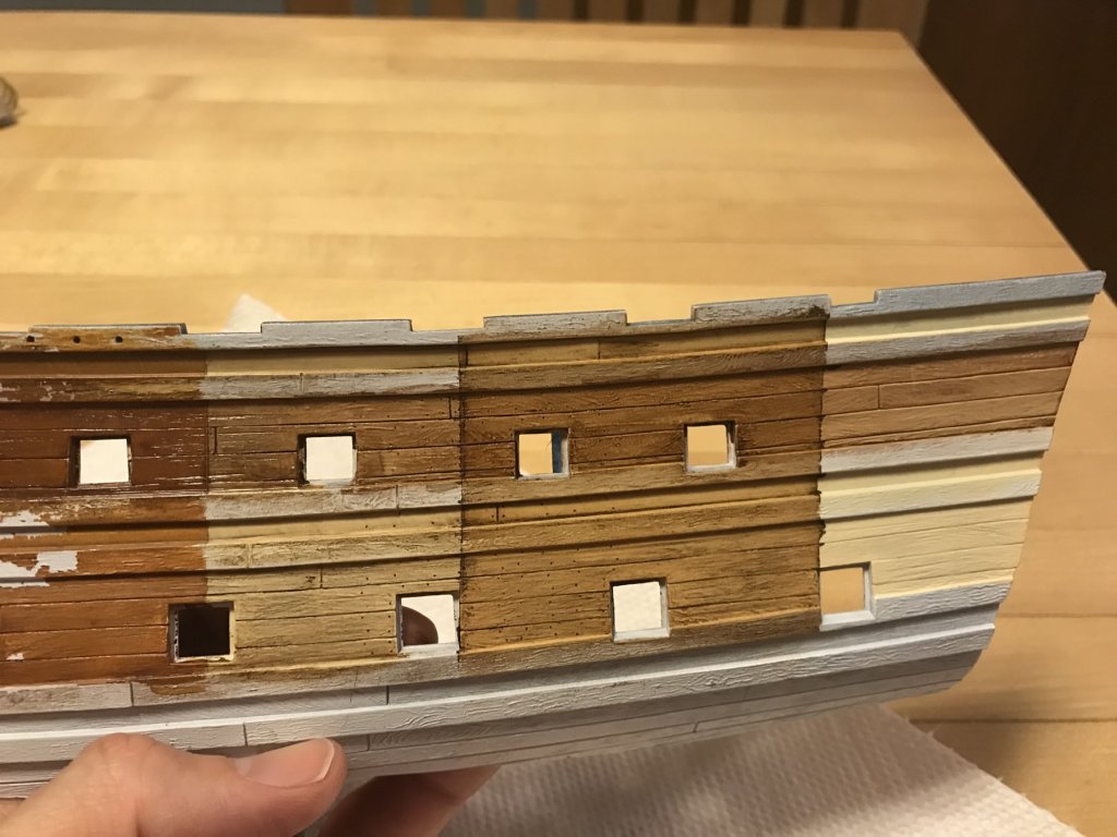
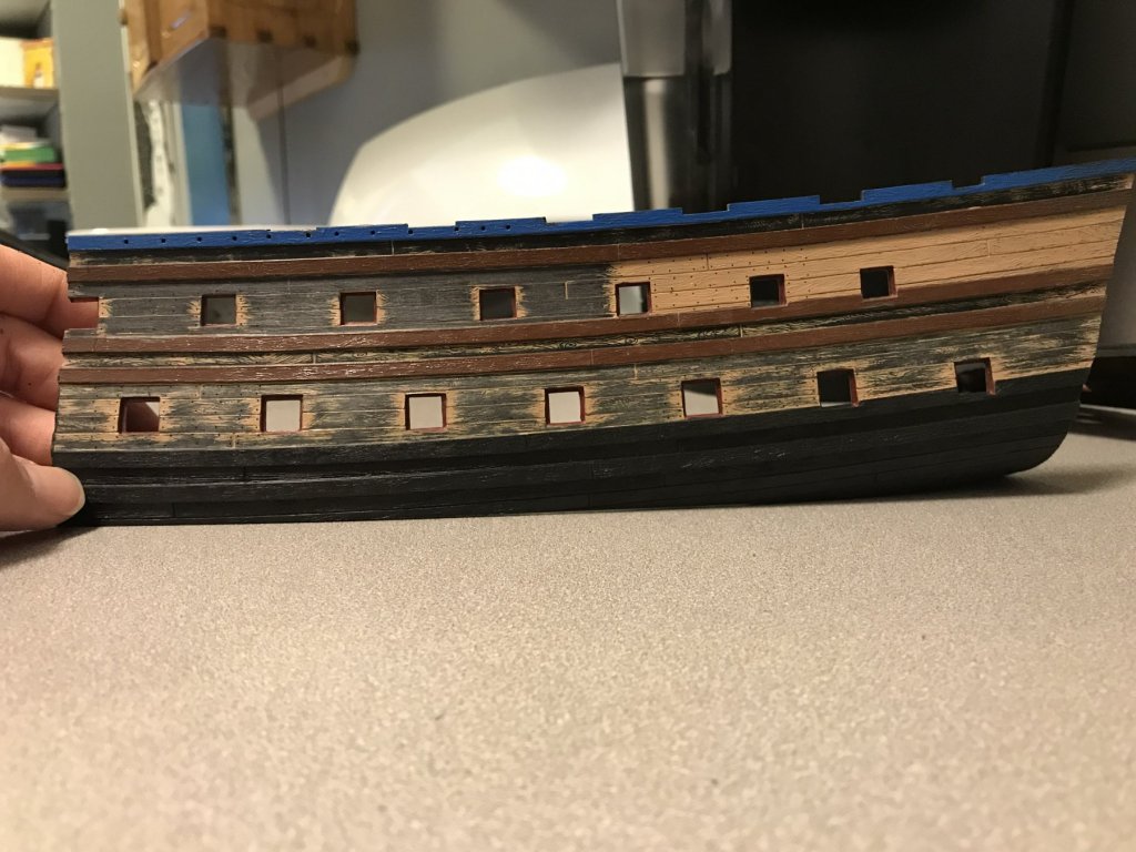
Things get interestinger and interestinger. Tonight, I painted the grey enamel wash over the entire lower tier of gunports. The wash dries quickly, so I then went over the bottom two strakes with the brown enamel wash. Here are the results: Again, the effect of these washes on the Raw Sienna is negligible. Both the grey and brown wash over the VDB, over the random tan (lower tier, lower two strakes of planking, second sample stripe from the stern) would make a really great paint protocol for decking, me thinks.

- 2,699 replies
-
- 7
-
-
- heller
- soleil royal
- (and 9 more)
-
Thanks for the links, Doris. I will definitely be checking those out!
- 1,035 replies
-
- 7
-
-
- royal katherine
- ship of the line
- (and 1 more)
-
Hey EJ! Always in the past, I had been intimidated by this sort of thing, but the paint application is incredibly easy. You could almost be careless with a blotchy base coat, and that might yield an even better result after the washcoat(s). It seems that the key to these finishing techniques is that your surface prep has to be on-point. It will be a pain to go back, now, and carefully scrape and sand around my gun carriage through-bolts, but I know that the effort will be worth it.
- 2,699 replies
-
- 3
-
-
- heller
- soleil royal
- (and 9 more)
-
Hello Doris, As ever, Katherine is a dazzling display of ornamental wizardry; a true feast for the eyes! I notice your tree-nailing pattern alternates every other frame. This is something that Dan Pariser had researched for his Queen Ann’s Revenge build, and a pattern that I adopted for my build. I wasn’t sure whether it was necessarily correct for Soleil Royal in 1689, but In the absence of more concrete information, I went with it because I like it. Do you have other more specific information about this nailing pattern? Whether it is specifically English, or more broadly in use throughout Europe? Just curious.
- 1,035 replies
-
- 9
-
-
- royal katherine
- ship of the line
- (and 1 more)
-
Thanks, Dan! You are right that the ship would not have been overly distressed. The diorama will show her a couple of years after the Battle of Beveziers and just before her unfortunate demise at Barfleur. She’ll be provisioning, at Brest, with the arsenal walls, off in the background. I’m pretty sure I’m going to go with this: I will still do a strip of grey wash, just to see, and then I’ll do the brown enamel wash over the grey to see what THAT looks like. There may be an application for some or all of that down the road. Anyway, I appreciate your looking in.

- 2,699 replies
-
- 6
-
-
- heller
- soleil royal
- (and 9 more)
-
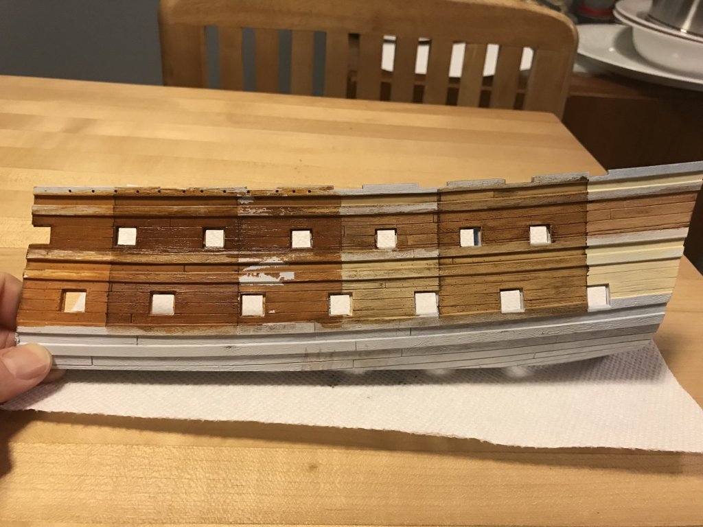
So, tonight, I brushed the enamel stain over the entire upper tier of one of the samples, and the results were interesting. At first, out of concern that the solvents would soften the acrylic, I wiped away the excess after allowing it to sit for about 30 seconds. This imparted some color - most obviously to the previously un-treated Random Tan - but the results were’t dramatic. The acrylic didn’t smudge or seem to soften. Next, I brushed on a liberal coat of enamel stain, and then spread away the excess with brushing strokes in the same direction. Here are the results: The effect is more subtle, over the Raw Sienna, but a difference is apparent when you compare the top and bottom swatches. This stain pretty effectively adds an additional layer of grime. I’m not sure I necessarily want that, but then I’m not sure I don’t. It also imparts a semi-gloss sheen, bit the clear seal-coat will reduce everything to the same sheen. I also have a grey wash of this type. Maybe tomorrow I’ll coat the lower tier with that and see what it looks like.
- 2,699 replies
-
- 7
-
-
- heller
- soleil royal
- (and 9 more)
-
Welcome to MSW, Mark! I'm looking forward to seeing what you are up to - Marc
-
Excellent research and execution, Dan. Also, good catch on the stanchion askew - otherwise, I was gonna have to be the jerk to point it out to you 😉 ”Hey guys, check out all the progress I’ve made! ... yeah, yeah but that single stanchion!” This is a remarkable model, Dan. I’m really enjoying the build.
- 238 replies
-
- 5
-
-
- leviathan
- troop ship
- (and 2 more)
-
Hey Mike! Thanks for dropping in and for commenting. As always, thank you to everyone else for your likes and comments. I hear what you’re saying. I will definitely do the masts and spars out of wood for tensile strength, and the fact that the kit supplied parts are out of proportion with period practice. Everything else, though, is just easier to make from plastic. Acrylic paints make it easy to get a level finish and these distress washes are super easy, and add a ton of life to the model. I think I will do the decks in plastic because I want to mimic the tapering of deck planks, fore and aft, and it would just be easier to lay this out and scribe it in. A little texture with sandpaper; paint; distress wash with maybe something in the grey scale, and you’re done! I’m also not in love with the idea of marrying plastic-made fittings like deck railings to wooden decks. I want the model to hold up for as long as possible, so mechanical bonds are less than ideal.
- 2,699 replies
-
- 4
-
-
- heller
- soleil royal
- (and 9 more)
-
These cathead supports reslly came out nicely, EJ. The head is really coming together now. Great work!
-
Why not reduce the inboard faces of the bulkhead extensions by a uniform dimension, using a rotary tool to waste and a flexible sanding stock to fair the bulkhead extensions to each other? My concern is that planking between bulkhead extensions will always look like a workaround, and that it will be distracting on the finished model.
-
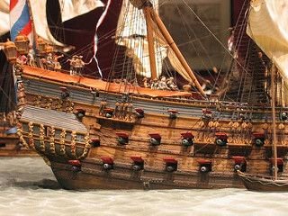
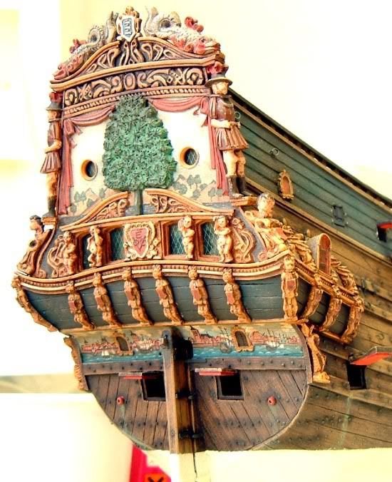
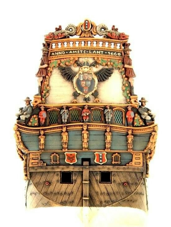
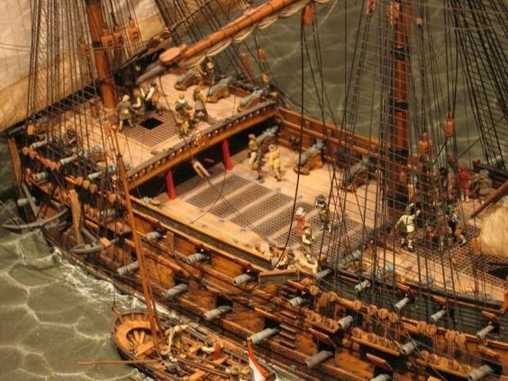
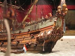
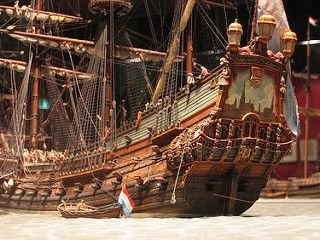
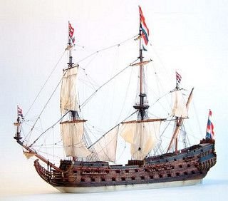
Thanks, Dan! The Raw Sienna is kind of having my cake and eating it too. If this were a full-hull, static display model I would probably paint just the Raw Sienna, as it is, because this was the color that I prefer for approximating the traditional "Ventre-de-Biche" that the French painted their ship sides with. In my heart, though, I wanted to simulate a wooden appearance even though the ship's sides would certainly have been painted to protect the iron nails. In the end, I have decided, this model is in large part about the sort of impression it leaves the viewer with, and I want to leave the impression of weather, and patina, while also hearkening back to a more historically correct tone, if not color. In thinking on it further, I will probably be able to spot-brush the walnut wash onto the yellow ocher of the upper bulwark frieze, as well as the red ocher of the main deck level. This will give the upper bulwarks just a little bit of age without going whole hog and washing over my blues completely; just a little bit of grime in the cracks and crevices to balance the whole thing out. As a reminder, here are a few of Herbert's excellent models from his Texel Roads diorama; all entirely scratch built from plastic masters, from which he makes resin castings: The hull work couldn't look more real and convincing if you were bobbing in a chaloupe right next to them!
- 2,699 replies
-
- 3
-
-
- heller
- soleil royal
- (and 9 more)
-
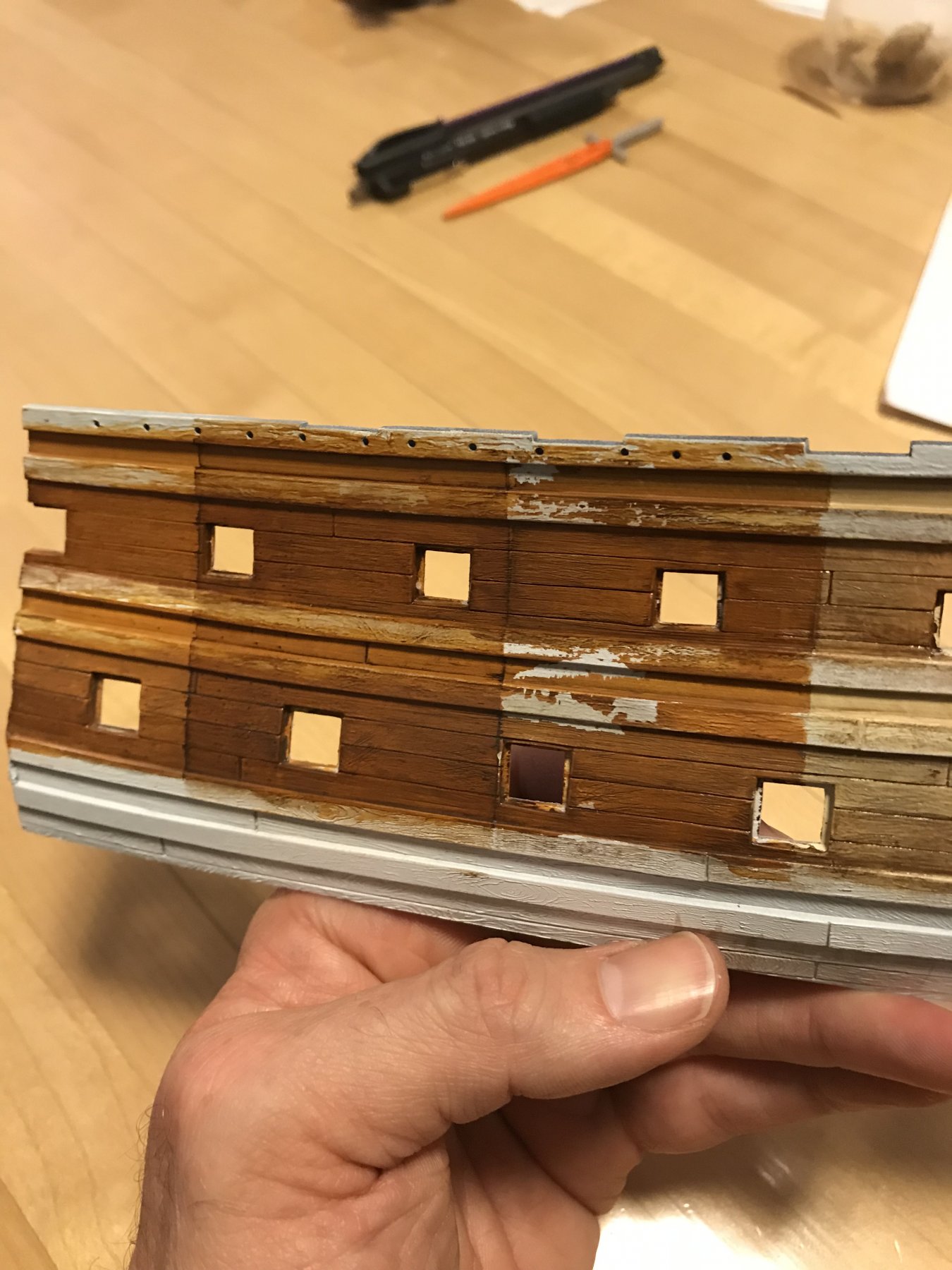
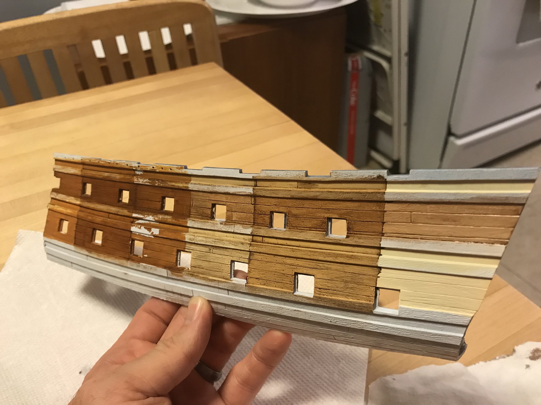
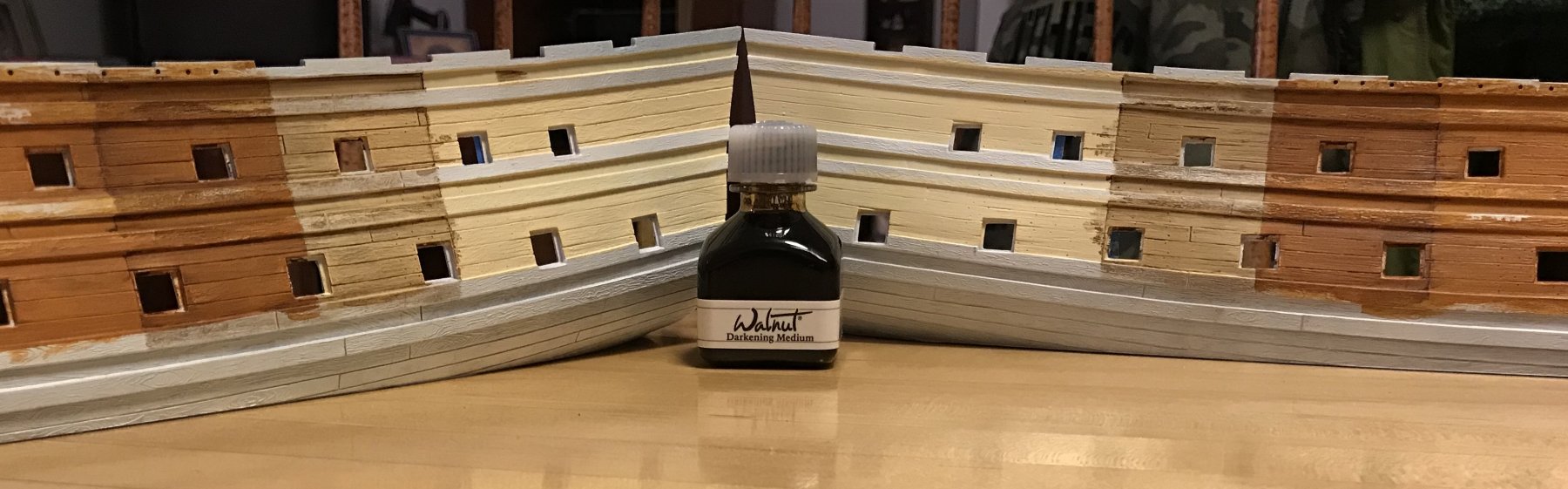
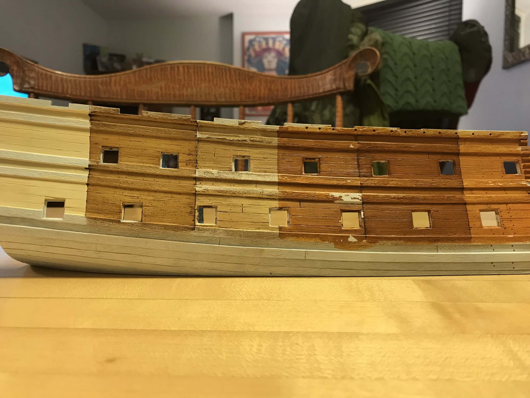
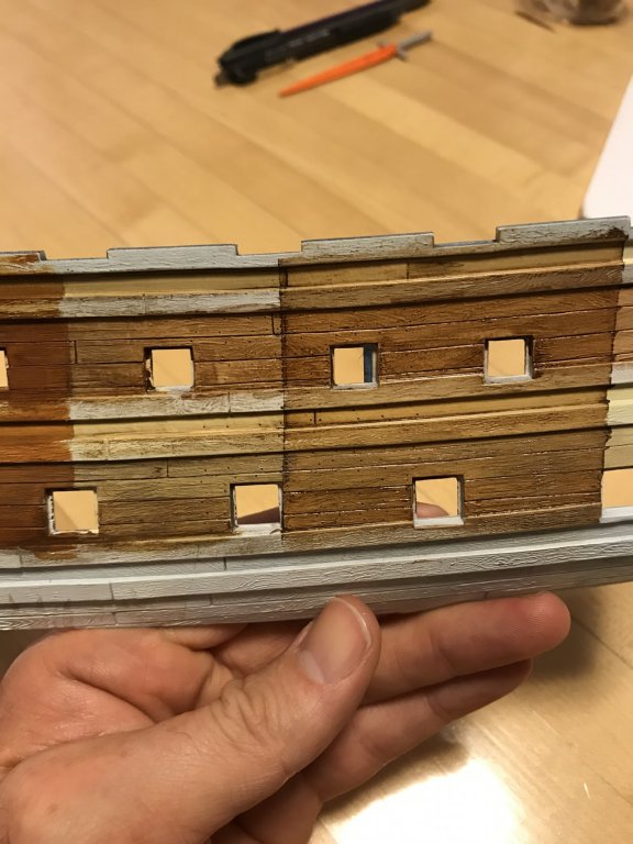
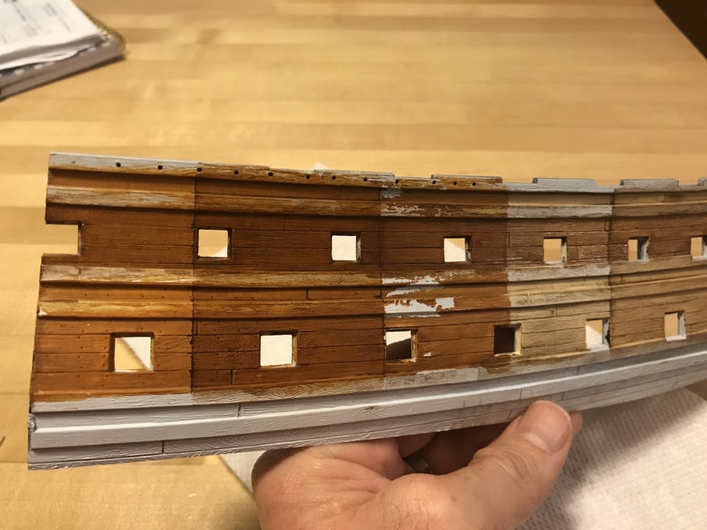
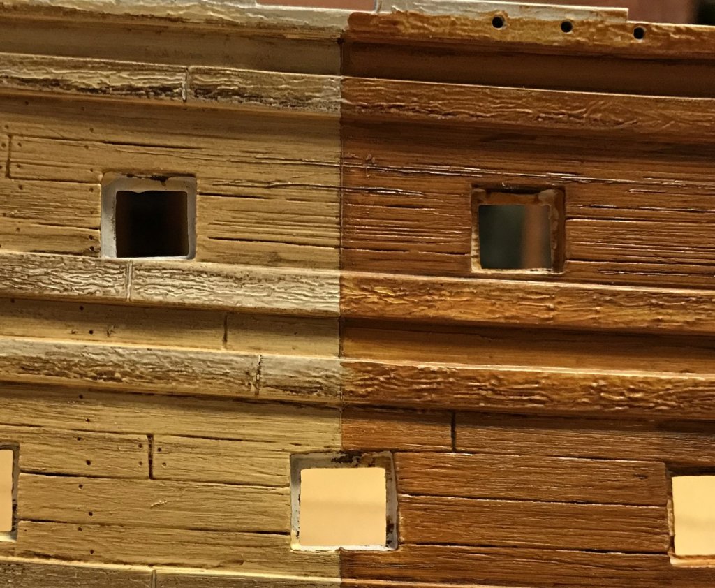
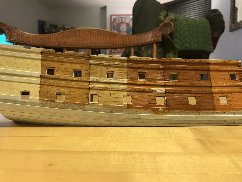
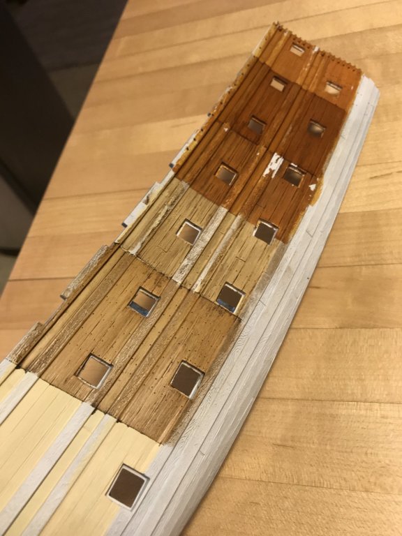
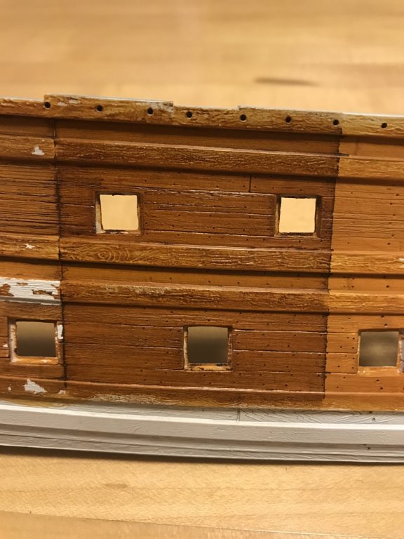
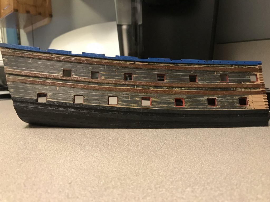
So, my plan was to follow a paint protocol that was developed by Herbert Tomesan of Artitec Modelbeau. Fairly simply, it is the following: A primer base coat, followed by light acrylic wood tone (I used ModelMaster Random Tan, and also Academy Raw Sienna), followed by full strength Windsor and Newton Van Dyke Brown (brushed on thick like shoe polish), then wipe away excess with rags, Q-tips and a coarse (chip) brush, and finally a soft brush, if you desire. It seemed so straight-forward, and in fact, it was! Calling back to an earlier post, when I expressed concern that my nail holes would end up popping too priminently, I first brushed on two coats of dullcoat, across the entire upper battery, before priming. After priming, this did seem to make a small difference, but then after two coats of acrylic base coat - there was a notable difference. The ModelMaster acrylic paint is a dream to brush on directly from the jar. Two coats were necessary, but then the color saturation was consistent. The Academy artist acrylic in the tube, on the other hand, is a much heavier consistency, and it took some experimentation with adding water to get a consistent even color. Maybe next time, I’ll get it right and only two coats will be necessary. Working from the center of my samples, toward the ends, I decided to first experiment with the walnut ink (made from actual walnut shells). At first, because it’s so watery, I did not think I would get much color penetration into the acrylic. It wiped away easily, though, and to my surprise - gave the surface an instant patina. You can see the difference between the stained sections and the raw acrylics quite clearly. The walnut really got into the sandpaper scratches, and left just a slight indication of the nail pattern. I was getting really excited about this! As for “wood” tone, I thought the walnut stain left the Random Tan side looking kind of dead, for lack of a better word. Maybe like weathered oak, but it wasn’t nearly the impression that Herbert’s models make. On the Raw Sienna side, though, the walnut stain gave better depth to the base color and the two of them, together, had a warmer, more appealing tone. Then, tonight, I masked off for the Van Dyke Brown oil paint. I guess I had pressed the masking tape on with too much force, because it took some of the Sienna basecoat off with it. That won’t be an issue when I paint the actual model, though. Well, the VDB oil is very much like shoe polish, and I was skeptical that removing it wouldn’t be a huge chore. Much to my amazement, the bulk of it wipes away really easily. I let it sit there for five minutes, or so, but the paint has driers in it to speed the cure time, so I didn’t want to wait too long. Wow, what a difference! Both base acrylics looked much richer with the VDB. The chip brush really helps to soften the wash coat and even the whole thing out. Here are a few detail shots: I may end up using the Random Tan/VDB combo for the decks, if I end up making those from plastic. I will almost certainly do the Raw Sienna/VDB combo for the lower hull, between the wales. I will still paint in the wales on these samples, and some of the gun port linings just for practice and to get a better sense for the whole thing. I also have a brown enamel wash that I will try, just to see what that looks like. I’ll post pics of that, if it’s any good. Whichever way I go, I think the key is just to work in manageable sections (4-5 gun ports in a row), so that I can remove paint carefully around all of my applied detail. As for varying the degrees of moulded grain removal - it does seem to me that the more grain one scrapes and sands away, the better this technique appears. The patch where I left the kit grain intact just ended up looking kind of muddy. I won’t mess with my wales, though, because they are fully detailed, at this point, and the flat black paint will minimize the difference in surfaces. If anyone is crazy enough to go through all of this in the future - they’d be well served to scrape away all of the raised grain before adding any detail.

- 2,699 replies
-
- 6
-
-
- heller
- soleil royal
- (and 9 more)
-
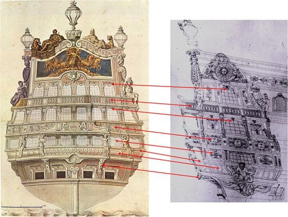
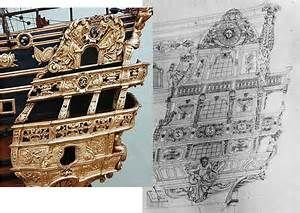
Hi Daniel! No, not yet, but it is on my Christmas list of the only thing that I want. My wife has been informed, and is quite happy to have the guessing taken out of the equation. I’m excited for the St. Philippe because this new monographie will provide an invaluable bridge between the First and Second Marines. I suspect that it will be quite possible to use this work as a starting point and to work backwards, in the century, toward the first Soleil Royal (referencing the work and research of Frolich, Saunier, Devroude and the Album de Colbert), as well as forward to the second SR. As ornamentation goes, I believe Berain’s stern is recreated exactly for the second SR, but that the quarter galleries and frieze would reflect the changes on the new navy, presenting a more austere ornamental scheme that still harkens back to the rebuild of 1689. A little food for thought for your next project, should you decide to go that route: You mention that you are selling your SR; is this a kit you haven’t started, or a model you have completed and would like to sell? Out of curiosity, which kit is it?
- 2,699 replies
-
- 2
-
-
- heller
- soleil royal
- (and 9 more)
-
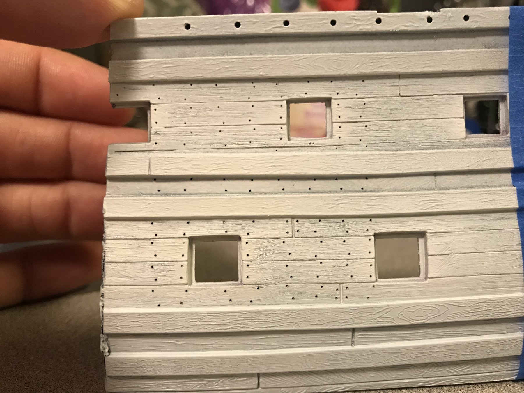
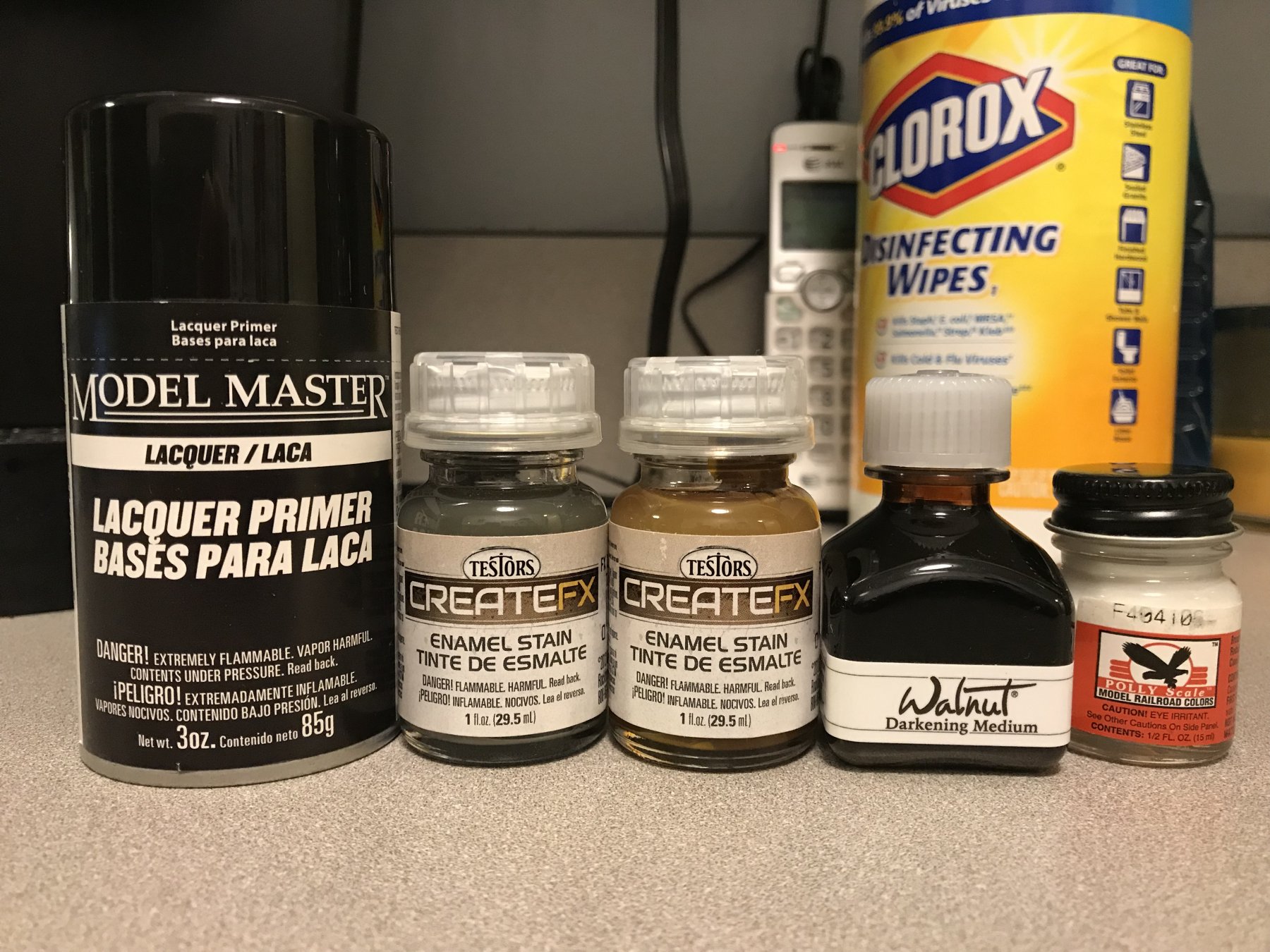
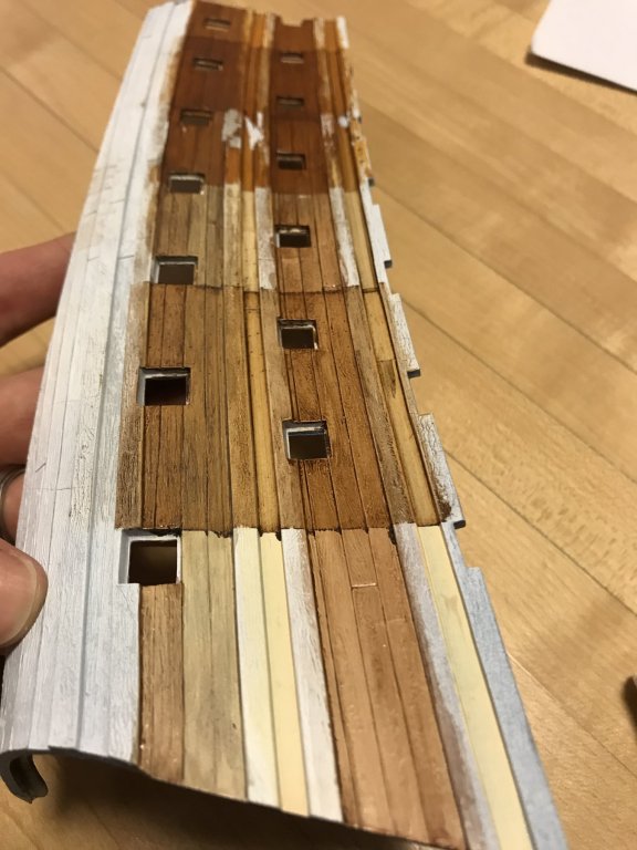
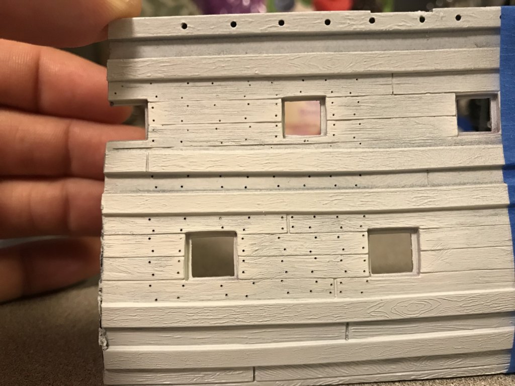
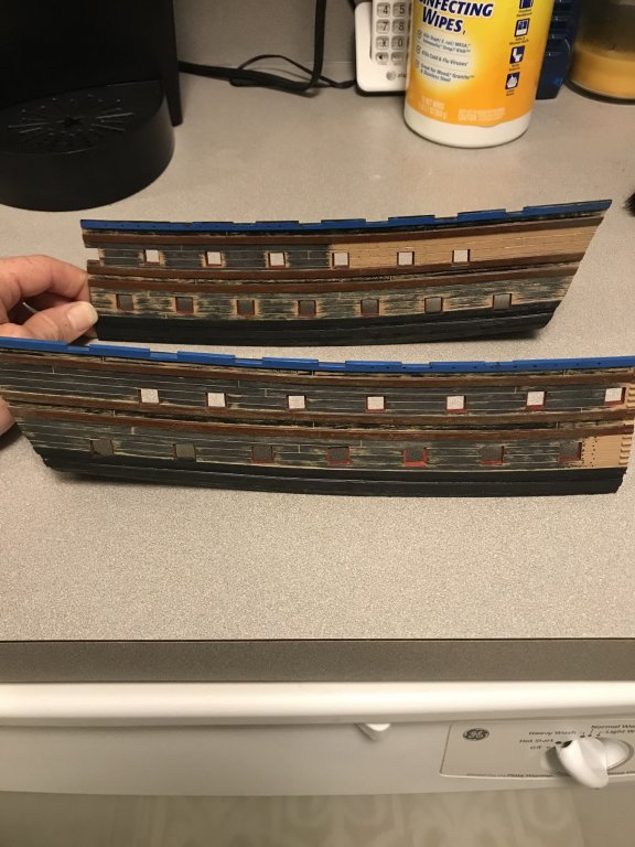
The build-up to Thanksgiving slowed my roll quite a bit, these past few weeks, but I did manage to prep my spare hull blanks for experiments in paint protocol. All the modification and prep work I’ve done is wasted, if the paint work doesn’t lend a level of realism that a waterline diorama calls for. One of the things that struck me was that my decision to represent the nailing of the “dead works” would probably telegraph a little too severely, through the paint, and especially after any kind of distress wash was applied. On the actual ship, with the deadworks painted, the nailing would hardly show, if at all. Thinking back, I remembered a brush-on acrylic product called dull-coat that had enough paint solids in it, perhaps, to fill those drilled holes just enough so that they remain a mere suggestion, and not a stark hole. The other challenge is that Herbert Tomesan’s paint protocol for realistic, weathered wood depends upon scratches into the plastic, in order to retain enough of the distress wash, thus patinating the surface in a realistic way. The Heller kit, on the other hand, has raised, moulded grain detail, which will definitely retain some of the distress wash, but the effect will be very different, and I’m not really sure that’s what I want. So, with all of that in mind, here is what I have to work with: I found that Testors makes this super-fine flat-white primer now in a rattle can. This will be my primer base. I also picked up a couple of Testors enamel washes to try over my acrylic base color. One is a medium brown color to be used as an overall distress wash. The other is a dingy grey that I intend to experiment with for the sort of vertical water streaking, you would see beneath scuppers, and flowing down from the sides of any hull protuberances, like the channels, for example. I also think this grey can be brushed directly over the flat-white primer, for the thin remaining strip of lower hull, below the water-line, that will still be visible. That should dinge-down the white a bit. Although, it’s not pictured, I plan to experiment with dry-brushing some shade of algae green, also down from the water line. Next to the enamels is a bottle of walnut ink that might make for a good overall distress wash. It shouldn’t present any compatibility problems with the underlying acrylic, which the enamel washes might because they are solvent-based. Also not pictured is a tube of artist oil, Van Dyke Brown, which is what Tomesan uses as his distress wash, over a light sand acrylic base (also haven’t bought that secondary, lighter color yet). Finally, the milky white stuff is the dull-coat. Here are my paint blanks: I’ve cut away the lower hull so that I can practice cutting in the top edge of the wales - a detail that Henry had executed to perfection, by the way. The other benefit of doing so, though, is that I will be able to see more clearly what my waterline distressing will really look like on the finished model. Next I drilled in smaller sections of the nailing pattern. I just eye-balled it, so it isn’t as neat as on the actual model, where I used a straight edge guide. Then, I scraped and then sanded (with 80 grit garnet paper) the lower and middle deck tiers to varying degrees of leaving moulded grain detail. The idea is to see what the distress washes look like in different combinations of scratched and raised grain. One issue is that I had already applied my through-bolts and washers for the gun carriage tackles to the finished hull. I really don’t want to scrape this detail away and re-do it, just so that I can sand down my hull grain before painting. So, in order to avoid all of that, you can see in the lower picture, lower deck level, that I carefully scraped/sanded between the ports, taking care to avoid the area just to either side of the port opening. Well, this will all be an experiment to work up something that I like, but it will be time well-spent. In research news, I’ve had some back and forth with Michel Saunier, regarding the placement of the ship stoves, which I’d like to represent, as well as the period practice of constructing the lower masts. Michel gave some good advice there, which I will expand upon when the time comes to focus on those things. I have also struck up a correspondence with Tony Devroude, who if you are not familiar with him, is the only other person, besides Michel Saunier, whom I have discovered to be building large, fully-framed models of French first-rates from the First Marine of Louis XIV. I would include Marc Yeu, in this group, but his excellent model uses a different construction method. Mr Deveoude has developed his own plans for a model of Le Dauphin Royal of 1668, that pulls from a variety of contemporary resources, as well as the research of the late Mr. Boudriot, J.C. Lemineur, and the still existing architecture and furniture that were produced by the same artists and artisans responsible for the Dauphin Royal. His research, which is detailed in a two-part series of articles for the NRG quarterly, back in 2010 is truly fascinating and still obtainable through the NRG website. In the intervening years, though, Mr. Devroude has obtained better information, in some respects, and he is very graciously answering a number of questions I had of the period, and of his model, in particular. With his permission, I hope to copy the full text of his responses into this build-log. Stay tuned!

- 2,699 replies
-
- 6
-
-
- heller
- soleil royal
- (and 9 more)
-
Also, just taking a quick glance back at your earlier posts - the carving castings look to be of a pretty decent quality. Will you use some and remake others, or do the whole ornamental scheme from scratch?
-
There have been some very nice builds of this model, here, on MSW! Per usual, you are off to a brilliant start, EJ, and I know your willingness to upgrade and experiment will propel this build into the next level. I look forward to following along. This kit is 1:90. Is this the same scale as SR and La Couronne?
-
No worries, Patrick. The extreme detailing has been going on for a long time now, and it all started with the lower hull.
- 2,699 replies
-
- 3
-
-
- heller
- soleil royal
- (and 9 more)
-
Hi Patrick! You are absolutely correct that there are alignment issues with the lower hull, when you build the kit straight out of the box. That is, in part, why I decided to cut away the lower hull altogether, below the waterline (which I raised by a solid 1/4”, BTW), and make the project a waterline diorama. Ever since I saw photos of Richard Romaniak’s SR - which I had assumed was also cut down, but was actually photographed on her waterline in actual water - I had thought that the Heller model looked much better balanced without her abbreviated lower hull. If you go back to somewhere around page 8 of this build log, you will see that cutting her down was the first modification I made. Doing this was the only way that I could possibly broaden the ship’s beam enough to include the missing sixth stern light. I took great care, while fitting these new bow extension pieces (which were salvaged from a donated (Thx again Popeye2Sea!), damaged hull) to ensure that the alignment fore and aft was true, and that the stem halves were square to the centerline. At the time, this involved some fiddly heat bending of the thick plastic over an open flame, but luckily the extension pieces didn’t collapse into molten pools of uselessness. The hull is fairly large and cumbersome to paint when assembled, though - especially details like all of the gun port linings, where it is advantageous for the work to remain flat while painting. On the other hand, when I am trying to cut-in the top edge of the wales, in black, it will be particularly handy to simply stand my hull halves up on the table, so that my brush hand can ride along the table, as I pull my strokes.
- 2,699 replies
-
- 4
-
-
- heller
- soleil royal
- (and 9 more)
-
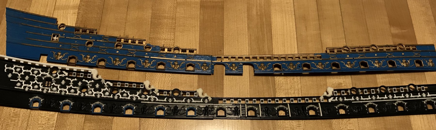
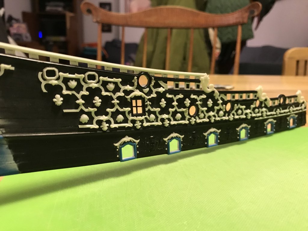
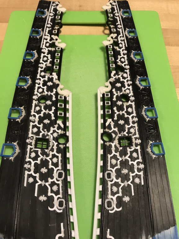
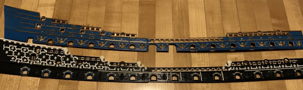
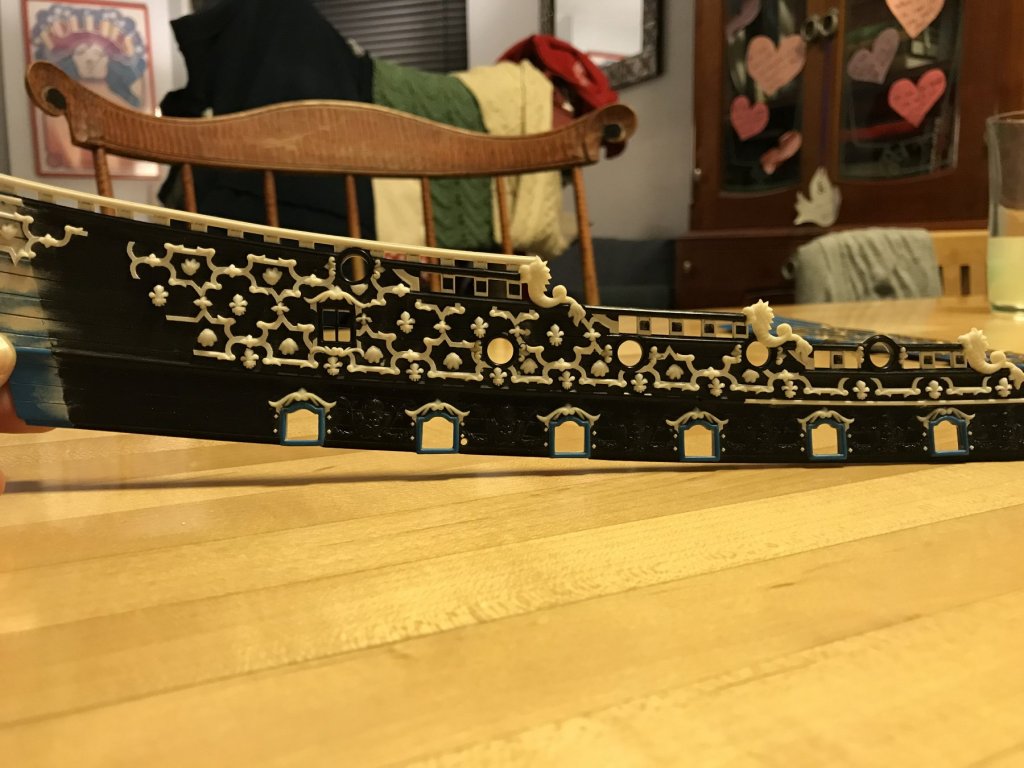
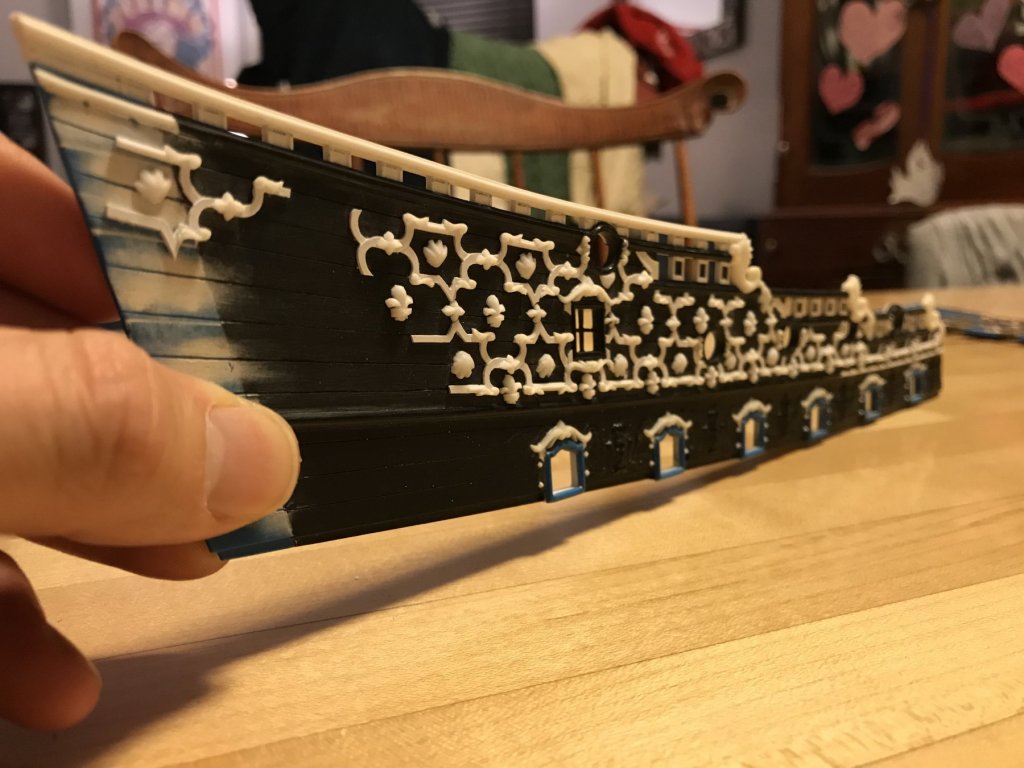
After several months of effort, I have finally completed the frieze on the starboard side, at least. I’m still ornamenting the port quarter. Here’s one last comparison shot: Taken as a whole, I think this experiment in stretching Berain’s frieze downward and forward is a success, even though it is not what was strictly drawn. I happen to think that the acanthus escutcheon carvings are just too large to exist between the quarter deck guns, and that their presence, at that location, cramps the frieze. There are certainly many things wrong with the Heller kit, but their decision to move these ornaments down to the main deck level was a sound one, in my opinion, and one that was grounded in documented practice among SR’s contemporaries. A closer look: And, I think, a pretty fair run with the drift rails: While this particular phase of the project represents one of the most dramatic alterations to the kit, and the process of creating it was very educational and satisfying - it was also extremely fatiguing. I love it, but I’m kinda’ sick of it. While I still have work to do on these upper bulwark pieces - the upper amortisement of the quarter galleries, and the bow and stern angels - I will soon put these parts away for a while, after I have cut and framed the two small octagonal windows at the poop-royal level. Following that, I will focus on getting the lower hull halves painted so that I can mount them and begin actually building the model. I bought a sheet of 3/32” styrene sheet that will serve as the base cap of my waterline diorama. Dan Pariser once suggested using brass, instead, out of concern that a styrene base would warp. Styrene to brass sheet would be a purely mechanical bond. My thoughts are that styrene to styrene would provide a welded joint and I plan to gusset and epoxy the hull interior like crazy, for extra lateral stability. Does anyone out there have additional thoughts/experience on this point?
- 2,699 replies
-
- 10
-
-
- heller
- soleil royal
- (and 9 more)
-
I’m sorry Mark, but I have to call you on your modesty. Yours is approaching Amalio standards of flawless execution. He’s in a class, all his own, but you are not far behind. Recently, I saw the Kriegstein Collection model of the Royal James at an exhibition of the Dutch maritime master painters in Washington, D.C.. Now, this is an amazing example of the model makers’ art, of the period. Yet, when compared with much of the work being done today, it seems positively crude by comparison. Of course, the circumstances under which these models were made dictated that they speed up their process a little, and take certain shortcuts in their representation and/or omission of various details. Nevertheless, the models being made today are much more complete and meticulous records of previously obscured and forgotten knowledge. Your efforts and the efforts of everyone else that is dedicated to their process should inspire the next generation of modelers to jump down the rabbit hole. Just incredible! Take a bow, my friend, because you’ve earned it!