Hubac's Historian
-
Posts
3,314 -
Joined
-
Last visited
Content Type
Profiles
Forums
Gallery
Events
Everything posted by Hubac's Historian
-
 This is really an excellent build, and an interesting model. I will be following along with great interest. Really terrific work!
- 227 replies
-
- 1
-

-
- BlueJacket Shipcrafters
- Stephen Hopkins
- (and 2 more)
-
New way to mount your mast
Hubac's Historian replied to Geoff Matson's topic in Masting, rigging and sails
Really interesting tip - I love this idea! -
Such a stunningly clean build!
-
Shaping up nicely, Dan! I look forward to seeing her next week.
- 238 replies
-
- 3
-
-
- leviathan
- troop ship
- (and 2 more)
-
I am very excited by the release of the St. Philippe. As with L'Ambiteaux, this new monograph should provide a very necessary bridge between the First and Second Marines of Louis XIVs navy. The two models that were on display at Rochefort were extremely impressive.
-
Yes, on my Pinterest page, I have seen this stern image tagged for Soleil Royal. But, then, the connection of this stern view to the starboard quarter view is un-mistakeable, and that image is almost always labeled as the Monarque. The signature on the portrait seems to answer that question, but it is easy to see where the internet leads us in various directions. I have often seen what looks like a pretty amateur line sketch of the Monarque's stern, that is labeled as the Royal Louis. I have yet to find an attribution for that line drawing. That both ships were built in the same yard, within a year of each other, lends credence to the possibility that both ships would share similar architecture and ornamentation, even if they were built by two different shipwrights. Well, this build-log began with a bunch of open questions about what context in which to place all of this imagery. There are some things that I think I can reasonably say identify a particular vessel, or characteristics that fit within the evolution of 17th Century practice. I don't know whether I am right, or not, but I believe I'm closer to the truth now, than when I started. Just gonna' keep on digging.
- 2,699 replies
-
- 5
-
-
- heller
- soleil royal
- (and 9 more)
-
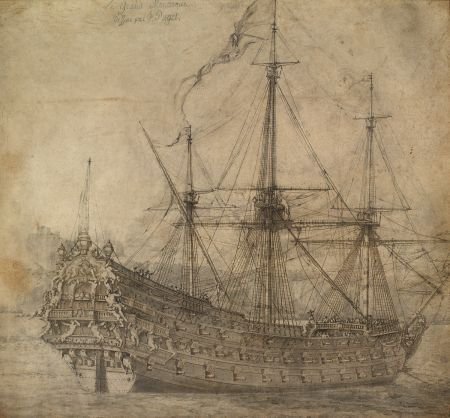
Well, at least one mystery is solved. If you enlarge the third, starboard quarter photo of the Monarque, you will see on the upper left corner of the portrait, an inscription that is partially legible; what you can make out is: ... Monarque ... par P. Puget I only noticed this after blowing it up on my home computer.
- 2,699 replies
-
- 6
-
-
- heller
- soleil royal
- (and 9 more)
-
You’ve been missed, Mark! Glad to see you working again. Interesting, the breaking point; was it an area of grain run-out, looking along the edge of the plank? Anyway, nice clamping work-arounds. She’s coming into form very nicely, indeed!
-
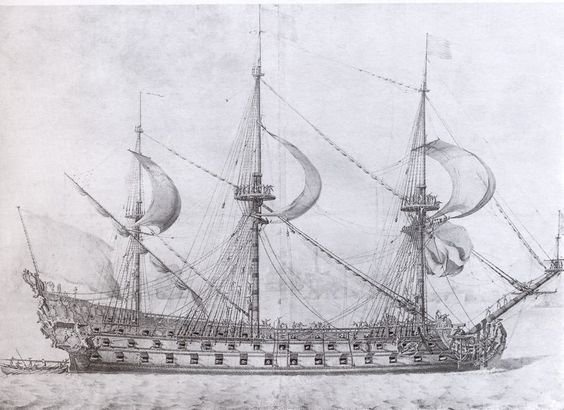
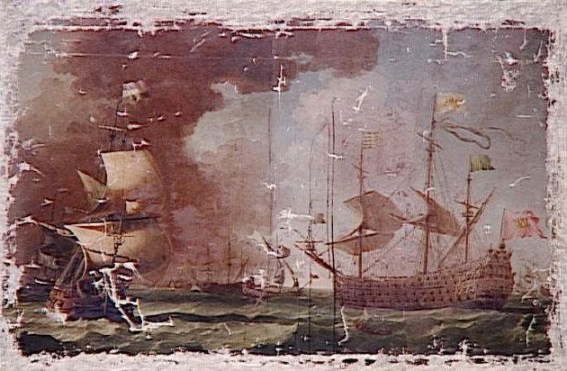
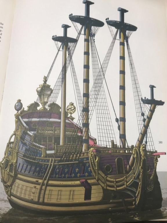
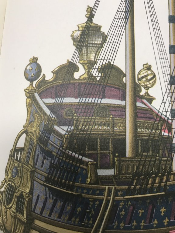
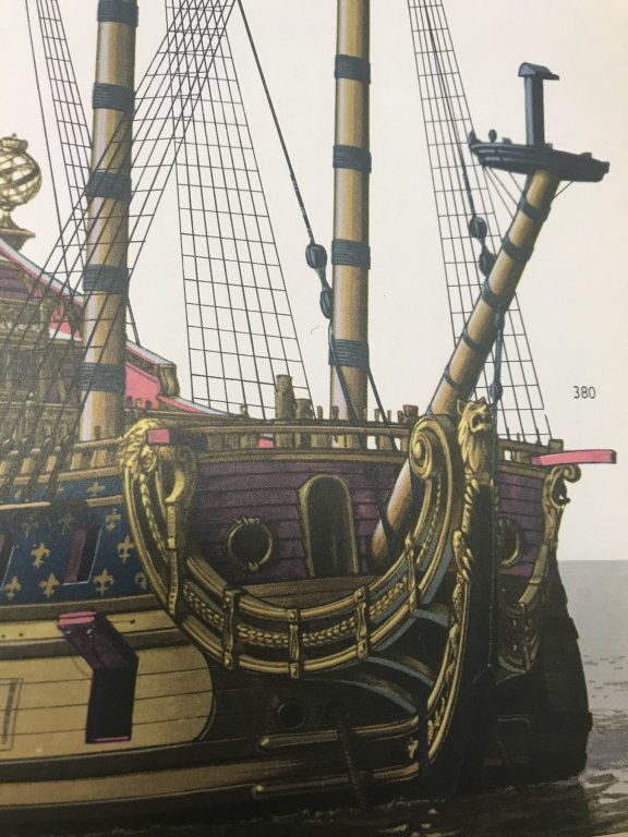
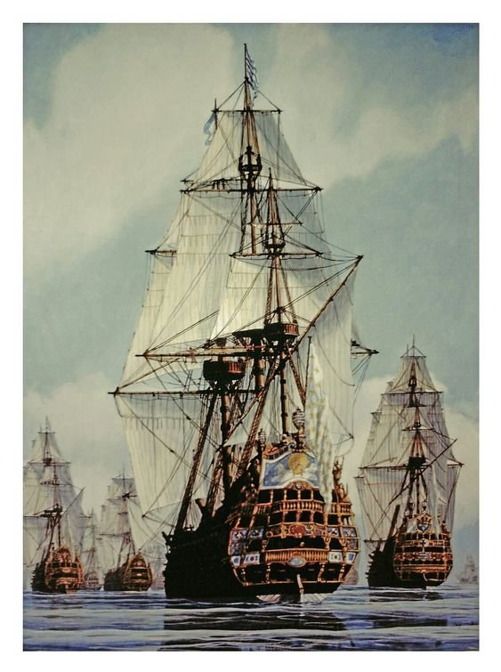
Thank you, EJ, for your kind words and thank you to everyone for your likes and looking in! So, I was quite surprised to find yet another amazing image of the Monarque of 1667. I keep coming back to this vessel because she represents, in my estimation, a pretty close facsimile of what Soleil Royal might have looked like in her first iteration. That every thing is drawn with such an acute sense of proportion and detail lends the portrait (attributed to Puget, who also designed the ornamentation for the ship) a sense of credibility that is akin to the work of the Van de Veldes. This portrait, below, agrees in every way with two other, better circulated images of her stern and starboard quarter, but shows her port broadside under sail. Here is a montage for your viewing pleasure. There is quite some debate, online, as to whether these images are of the Monarque or the Royal Louis of 1668. While the particular headrail arrangement and open, walkable tiers of the quarter gallery mark this vessel as an early construction of the First Marine, I believe the answer to her identity lies in a counting of the guns as compared with the lists of the Kings ships. The Monarque, built at Toulon, and launched in 1667 was armed with 94 guns. The Royal Louis of 1668 was also built at Toulon, but by a different designer, and her initial armament is listed as 120 guns. Counting the guns in the first picture, above, one arrives at 94 guns - according to what is visible; the possibility/likelihood of there being at least two bow chase guns, on the main deck level, only brings you up to 96. That is a far cry from 120. Now, up until now, I have been operating under the assumption that the following image is of the Royal Louis of 1668. However, in light of this conversation about armament, it seems much more likely that this is the Royal Louis of 1692, carrying 110 guns. According to what I have learned, so far, the significantly reduced sheer, the semi-closed quarter galleries and the triple-tiered headrails are more consistent with this later, Second Marine development of the kings navy. Counting the visible guns, and assuming four bow chasers and four stern chasers, one arrives at 110. So, there's that. If that is, indeed the case, then this portrait has particular value for my modeling of SR in 1688/89. Now, according to memory, I believe that Michel Saunier told me, once in response to a side conversation, that the following image is of the first Royal Louis: Perhaps that is so. It does appear to have the completely open quarter galleries. Interestingly, the image does show 16 guns on the lower battery, which only La Reyne and Soleil Royal were supposed to be armed with. Nevertheless, that 16th port, closest to the stem was only armed by moving the next gun aft, forward, when required. So, at most, the first battery would only have had 15 actual guns per side. I'll have to look back on that correspondence to confirm, but I think that is what Michel was telling me. Anyway, all pieces of a very complicated puzzle! Make of it what you will.
- 2,699 replies
-
- 8
-
-
- heller
- soleil royal
- (and 9 more)
-
Incredible attention to detail. I’ve always said that the first time you build something is when you get into the nitty gritty of drawing it. Fabulous insights into the why and wherefor!
- 54 replies
-
- 2
-
-
- 3d cad
- cleveland class
- (and 1 more)
-
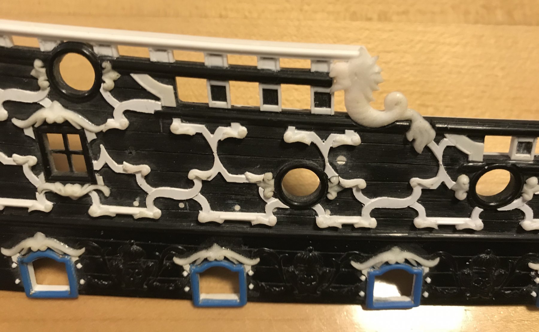
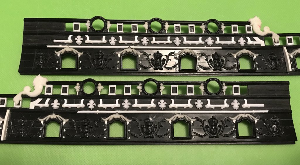
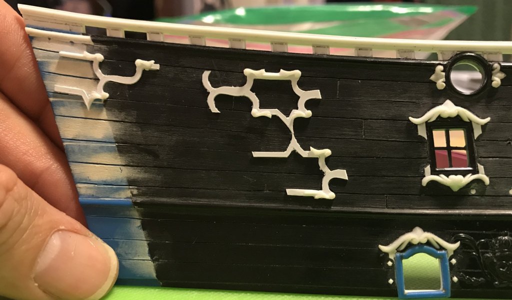
Applying the frieze is a lot like cutting-in wallpaper; you have to work your way into and around projections, without distorting the repeat of the pattern, and the only way to do that, really, is just to take your time. On the starboard quarter, the frieze is almost fully in place. There is one last small segment that bridges the two upper bulwark halves, but I will wait to glue this in, until after I have installed the upper bulwarks. I want this joint to be as seamless as possible. When you build the kit, as stock, much of the joint is covered over by the main channel. Now that I have lowered the channels, though, it will be imperative to do a good fill job on the joint. The stern quarter bulwark is scraped clean of any squeeze out, and the X’s have been lightly relieved to give a more three-dimensional effect. This piece is now ready to be adorned with foliate diamonds, shells and fleur-de-lis. I can’t write that without thinking of Lucky Charms cereal ☘️ This closeup gives a better sense for some of the difficulty of breaking the frieze up into smaller and smaller segments for the cutting in. Foliate diamonds will cover the joints in the center of the Xs, and will be let between the pointy joints where the upper and lower tiers of the frieze meet. I shortened the ears of the crowning ornament, above the window. This will make a more sensible layout for letting-in the foliate diamond, just forward of the window. On the other hand, the forward bulwark pieces were much more straight-forward, and placing them was much easier and faster. The difficulty with the forward bulwarks was fitting the fleurs. I still had to do a bit of shortening and re-shaping of the central petals to get them to fit within the allowable space. I still think they’re a little too large, but the effect is pleasing enough that I don’t feel motivated to make new, smaller masters; this is especially so, after seeing the now completed model of the Saint Philippe, with it’s diamond-hatch frieze of significantly smaller fleurs. Granted, the St. Philippe’s frieze is more dense. Nevertheless, smaller is better in both cases. Anyhow, this would be one of my hard limits on this particular model. It is close to what I drew, in the first place, and in scale with the black and white Berain drawing, where the fleurs are quite large. In wood, though, I would go the extra few miles to get it absolutely right.

- 2,699 replies
-
- 12
-
-
- heller
- soleil royal
- (and 9 more)
-
I’m really enjoying your process, here, Dan. Interesting tip on the wood hardener!
- 238 replies
-
- 4
-
-
- leviathan
- troop ship
- (and 2 more)
-
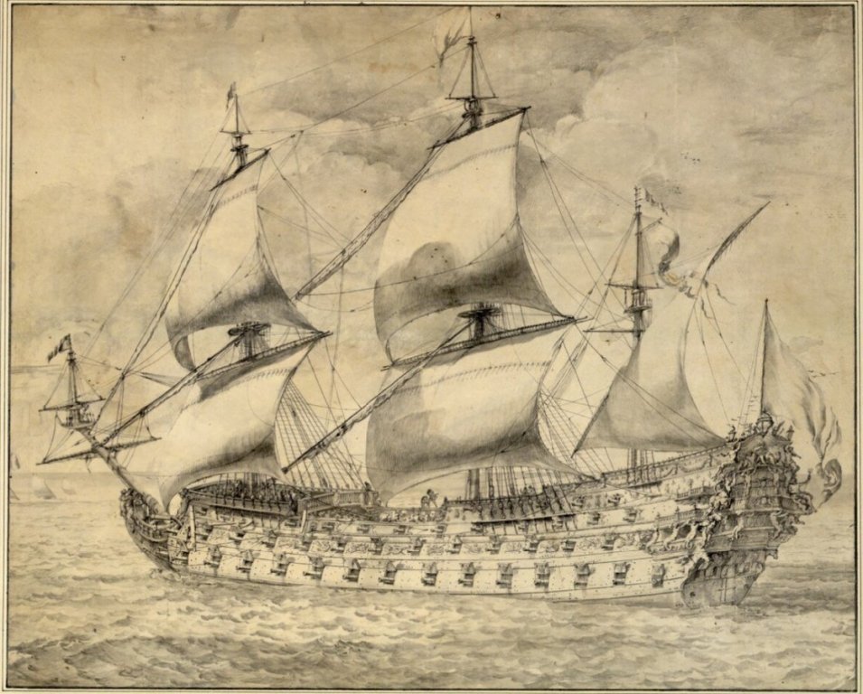
Yeah, I won’t be waiting too long on this one! In build news, the starboard frieze is going up nice and methodically. It’s a lot like wallpaper, with the cutting in and around ornaments and openings. I’ll post pics when I have a nice progression. In the meantime, here’s a nice rendering of a typical French second rate, of the period: This drawing provides a good sense for the convolutions of the quarter galleries.
- 2,699 replies
-
- 4
-
-
- heller
- soleil royal
- (and 9 more)
-
So, this is kind of a big day in my build-log! After much waiting, Ancre publications has finally released the monographie of Le Saint Philippe of 1693. This is a collaborative effort between Jean Claude Lemineur, and the modeler Jose Tusset. Here is the link: https://ancre.fr/en/monograph/93-le-saint-philippe-1693.html The reason this work is so significant to me, and particularly for this project, is that Le Saint Philippe was one of the new ships of the “Second Marine,” which was the major rebuilding program, following the losses at La Hogue. This rebuilding program marks the beginning of the long pushed-for standardization of French naval architecture into a codified rate system. Because SR’s rebuild in 1688/89 is so close to the re-construction reforms of the second marine - it is plausible that the re-built, first SR would have incorporated much of the design elements that would be incorporated into the new navy. My approach to modeling SR has always been a sort of forensic exploration, using contemporary sources to fill in the numerous blanks of the Heller kit. From the instant I saw early photographs of the Tusset model, I recognized many of the more prominent features of the model I was proposing to build. I expect that this new monographie will be an invaluable resource, and a much-needed one for the details of hull form/design, ship furniture, arrangement of armament, masting, rigging, etc. Oh, and did I mention that it’s available in English?! I know what I want for Christmas!
- 2,699 replies
-
- 5
-
-
- heller
- soleil royal
- (and 9 more)
-
As if your modeling skills weren’t enough, your photo-shop skills are second to none, Dan! It is amazing when you consider the deck to deck complexity of such a large vessel, that you can re-align all of that detail, and come up with a coherent set of plans. That effort, alone, is invaluable to the community. You are off to a tremendous start, here, Dan!
- 238 replies
-
- 5
-
-
- leviathan
- troop ship
- (and 2 more)
-
Hey Guys! The reason I didn’t paint the frieze lattice first is that I was primarily concerned with establishing a strong bond; I would hate, after all of that work, for elements of the frieze to just flake off, easily. In my view, this is no different than if the detail had been moulded into the kit, in the first place. In my twenties, I had a really steady hand for this. In my forties, I guess we’ll just have to see. The other issue was that applying the lattice has to happen in segments and controlling the squeeze-out is really difficult. With an already painted ground, you would be messing up the paint, anyway, to scrape the squeeze-out. Lastly, I couldn’t make the shallow relief cuts where the Xs cross until the lattice pieces are firmly mounted on the bulwark plates.
- 2,699 replies
-
- 4
-
-
- heller
- soleil royal
- (and 9 more)
-
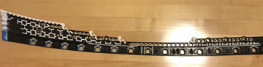
Alright, so after all of that tedious cutting out, I can begin placing the frieze lattice. Please bear in mind that this seeming, non-sensical gap will eventually be bridged by the upper finishing of the quarter gallery. In the meantime, I have left the ends overlong to allow for cutting in. Also, the edges of the frieze lattice may look a little ragged, but that’s just squeeze-out from the styrene cement, which will later be scraped away. These pieces are really welded on, now; I degreased the upper bulwarks and I give the backs of the frieze segments a light sanding before glue. I must have spent an hour checking and re-checking my starting point in order to be sure I allowed the propper space for the quarter gallery, but also in an effort to optimize my ornamental layout, so that I didn’t have too many oddly cut away shells or fleur-de-lis. There will be the odd one, here and there, but not many. Until now, I wasn’t really sure just how accurately I had measured and drawn the upper bulwarks and all of their piercings; I did pretty well, I think, to come +/- a light sixteenth. There was enough latitude to shift the whole layout left or right, in order to make the best of these discrepancies. So, more to come later. Thanks for looking in 😀
- 2,699 replies
-
- 11
-
-
- heller
- soleil royal
- (and 9 more)
-
I’m sorry to hear that, Kevin. I think the work you have done is truly outstanding! Do you know whether the new builder plans to continue the build with an MSW log of their own?
-
The rudder looks immeasurably better! Will you re-doing the stern post, as well?
- 146 replies
-
- 3
-
-
- deagostini
- vasa
- (and 1 more)
-
You may well be right, there, Mark. One thing is certain - the French were innovators in naval architecture, as a discipline; with innovation comes much experimentation!
- 2,699 replies
-
- 2
-
-
- heller
- soleil royal
- (and 9 more)
-
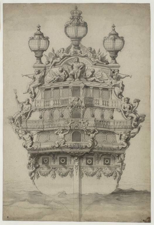
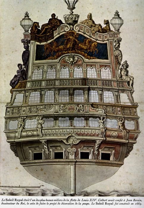
Interesting find on Pinterest, the other day: I have no idea whom the artist is, or when this was done, but it shows an interesting interpretation of SR's stern balconies; at all three levels, there appear to be only central projecting galleries, spanning the middle four windows at each level. This arrangement is very similar to this Puget drawing of the Monarch's stern: Here's the Monarch from starboard, quarter view: Perhaps these contemporary drawings were the inspiration for this drawing of SR. The reason that I don't think this interpretation is correct is that Berain's drawing, from the starboard quarter view, shows that the figure of "Fall" is supporting a projecting stern balcony of the middle tier, or main deck level. As "Fall" is positioned at the outer edge of the stern, at the juncture of the quarter gallery, this strongly suggests that the middle stern balcony projects at least to this juncture, and more likely wraps around and connects to the quarter gallery. As previously stated, I don't believe that the lower, stern counter projects into an open balcony at all. I do, however, believe that the upper stern balcony only projects across the middle two stern windows. Anyway, I like posting these artistic interpretations, as I find them. I suspect that they are often riddled with evidence of ship-building practice, at the time of the artwork's creation. There is nothing that I have found in authentic contemporary portraiture to suggest that the first SR would have had a mizzen t'gallent mast and sail. Later in the 18th Century, though, this would have been standard practice; perhaps this is a clue as to when the portrait was done. If nothing else, it is evidence of other people puzzling over the same problems of how to represent the ship. Whatever the case may be, it is a well-executed artwork, with nothing seeming grossly out of proportion. I like the use of red on the stern, as it is similar to what I intend for my model. The artist appears to have included Le Pheonix, to port of SR.


- 2,699 replies
-
- 7
-
-
- heller
- soleil royal
- (and 9 more)
-
Thank you very much, Backer! I hadn’t built a model in such a long time - not since a never completed Airfix Vasa that was coming along nicely until I learned that the upper works were actually red and not blue. I then lost interest, continued to carry it around with me through several moves, and finally shipped it to the great beyond, down the compactor chute, after so many parts had broken off. I regret it, now, because the paint work was really good, but it was pretty much a stock build. Fast-forward to now, and I have learned to enjoy the experimental possibilities and to try and push the craft to my limits. That keeps the challenge fresh and my interest stoked. It also gives me something productive to do at lunch and in the time before work. Little by little, day by day. It won’t be long before all of these modifications begin to take shape as an assembled thing. Thank you, again, and thank you to everyone who has stuck around. It is greatly appreciated!
- 2,699 replies
-
- 5
-
-
- heller
- soleil royal
- (and 9 more)
-
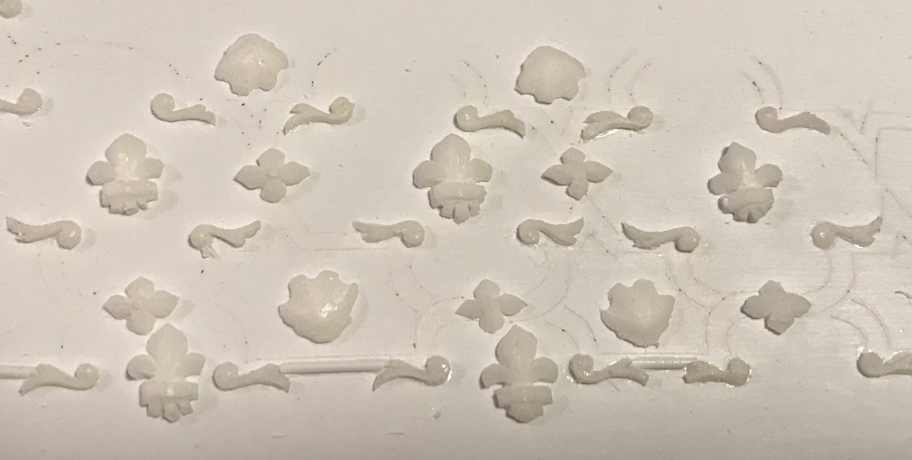
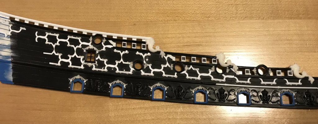
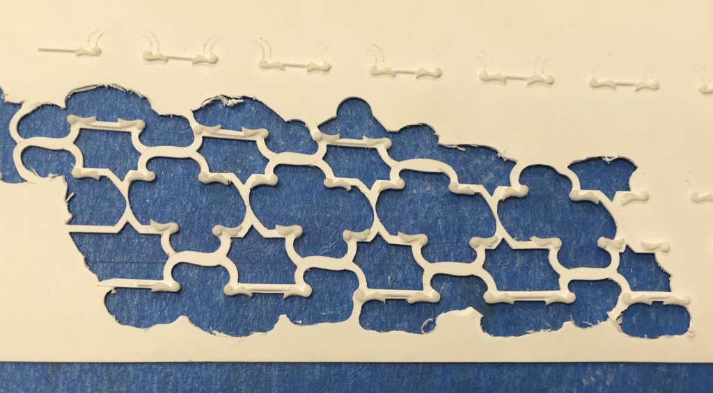
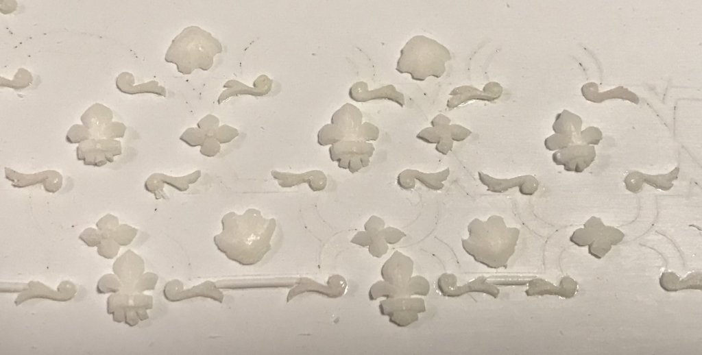
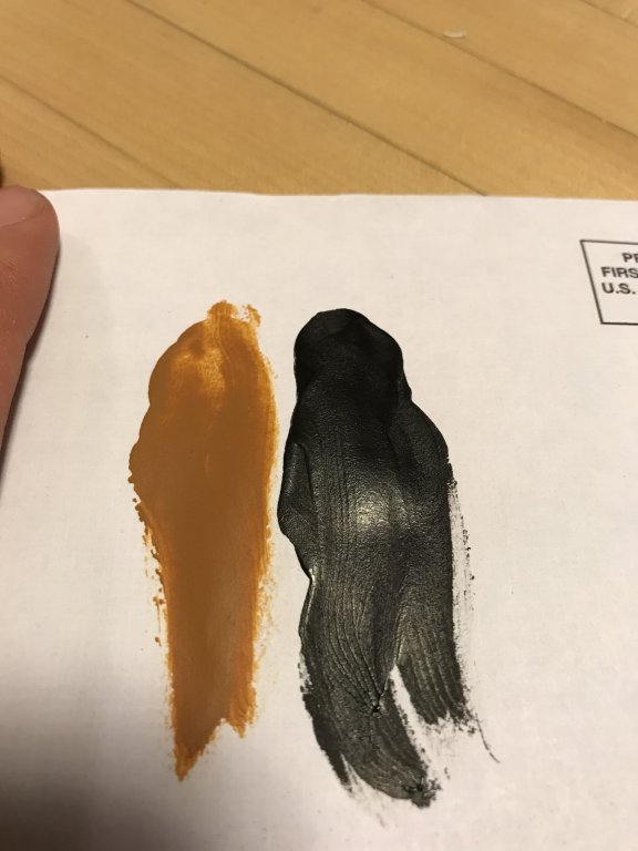
The lattice is coming, but it is incredibly tedious work to free it. I’ve cut across the lattice, at times, and had to fit in graving pieces. That is the beauty of plastic, though; repairs like that are easy and will be seamless on the finished model. The scrolls are fiddly and often come loose. I’ve taken to brushing the edges of the scrolls with cyano, as a preventative measure, as they come free of the ground. With all the ornaments made, now, I couldn’t resist placing them in a small section to see the spacing: I’m very happy with this, and it gives me the motivation I need to continue chipping away at the lattice. Finally, I’ve begun experimenting with acrylics. Grumbacher’s Academy line produces a Raw Sienna that perfectly captures my interpretation of the “Ventre de Biche” color that will span the lower and middle batteries, between jet black boot topping and wales: I’m glad, now, that Marc Yeu prevailed upon me to consider more period-correct, painted appearance for the so called “dead works,” which are iron fastened. I have some ideas about how to lightly weather the painted finish, so that it makes for a more realistic diorama. I’ll discuss that more, in detail, as I work through paint tests on my scrap hull.
- 2,699 replies
-
- 8
-
-
- heller
- soleil royal
- (and 9 more)