


Hubac's Historian
-
Posts
2,950 -
Joined
-
Last visited
Content Type
Profiles
Forums
Gallery
Events
Posts posted by Hubac's Historian
-
-
Doris,
I really am so floored by what you do. As is the case with your other models that I have seen, the Royal Katherine is so cleanly worked and her lines are so fair - if I didn't know it was a model, I would swear it were the real thing springing up before our eyes. You have such a strong sense for how the architecture of these floating batteries should look. And your resourcefullness, in finding such creative ways to simulate realistic details, makes you a ship-modeling genius in my eyes.
You answer one question for me and I have ten new ones. Rather than ask those questions now, though, I will do as you suggested and read through your Royal Caroline build log.
The basic question your models provoke is this: with results so clean and fair, using such simple materials and tools - why build a ship-model any other way?
Well, I will be watching with great fascination from here on out!
-
Hi Doris,
What sort of card stock do you use? Is it specialty cardboard that you might buy at an artist's supply? I was thinking I might adapt some of your technique to my model of Soleil Royal. I'll need to create new interior structural support and cambered deck beams because I am scratch-building all new decks in this, otherwise, plastic kit. My thought was that card would be easier to layout, cut and shape than styrene sheet, as an underlayment for what will ultimately be wooden strip planking. Or, would it not be advisable to glue wood strip to cardboard false decks, because of humidity fluctuations between different materials? Is that why you use plastic foils to simulate decking?
- mtaylor, FrankWouts, BETAQDAVE and 3 others
-
 6
6
-
-
What I need that I don't have right now is SPACE. Plastic models lend themselves pretty well to construction on the kitchen table, and then being tucked away in their custom made build-box until the next session; there's no putting away of machinery, just some simple hand tools and maybe a Dremel to deal with. Plus, I'd really like my scratch-build to be in a larger scale than 1/100. It takes a special talent to build 17th C. Men-O-War in small scales, and not everyone can be Donald McNary or Lloyd McCaffery. So, again, display space is at a premium in our small apartment. At some point in the actual build, I'll have to give away my first SR
 .
.
The other issue is that, while I'm quite a competent woodworker, I'll still have to learn the art of framing a few smaller wooden models before I take on something immense like SR. Some day... Some day!
-
Hey Vossie! Yeah, that was always my idea; that once I had finished with a plan, I'd publish it on the site for anyone to use, improve upon, etc.
Michel, I'm glad you are joining the discussion. There are many, here, who have expressed their gratitude for your contributions to my research, so far, and I am certainly not least among them.
I am in agreement with you, Michel, on all of the points that you are making, regarding the frieze space between the knees of the head, the size of the middle deck gun ports, and the alignment of the arched main deck ports. These are all inaccuracies of the Heller kit. And I will ask you to take the long view of what I am doing now, as it relates to what I plan to do further into the future; this project is providing me with a sound research base to eventually build an architecturally sound, fully scratch-built model of SR.
Some day, I will have the space and resources to make a really good wooden, framed model of the ship, and when that day comes, all of the resources and information you (and Mr. Lemineur, Mr. Peters and Cedric, among others) have shared with me, will come more fully to fruition. In the meantime, though, my objective is to make a much better model of the Heller kit than the kit, alone, provides for.
I am aware of the problems that you mention, however, there does come a point where one goes beyond kit-bashing to making a fully scratch-built model. If, for example, I am going to completely rebuild the bowsprit and headrails and carve a new figurehead, and scratch-build everything above the second battery, well then, I might as well draw up a correct hull plan snd make the entire thing from scratch. At this time, though and for a variety of reasons, I am just not ready to go that route. I'm capable of it, but not ready.
And so, with this model project, there are certain lengths I am willing to go to add a detail, and/or modify some aspect of the kit to try and correct some of its inherent flaws, and there are other things about the kit that I can look past, right now; like the too small second battery ports, or the run of the main deck ports, or that the space for the bow frieze tapers. That being said, I am always glad for the lesson in what should be because that is knowledge that will be applied to future models.
Dan, the f'ocsle deck is armed with three guns, each side, and they are just out of view in the Berain and Compardel drawings. I am 99% certain, now, that my reduced scale for the horsehead provides enough clearance for the cathead without having to alter anything about the position of the cathead.
the greatest value to me, right now, of this much clearer Berain drawing of the bow is that I can now draw a much improved bow angel. I'll trace this, instead, and scale it to fit.
As always, thank you to everyone who stops by, weighs in, and for those likes. Even, and perhaps especially, if you don't agree with what I am doing - I am interested to hear what you have you say.
All the best - Marc
-
Hi Doris,
I've wanted to witness your process for some time! I am so excited to see you build the Katherine, and I will definitely be following along. Your work is really exceptional!
Regards,
Marc
- Elmer Cornish, DORIS, mtaylor and 3 others
-
6
-
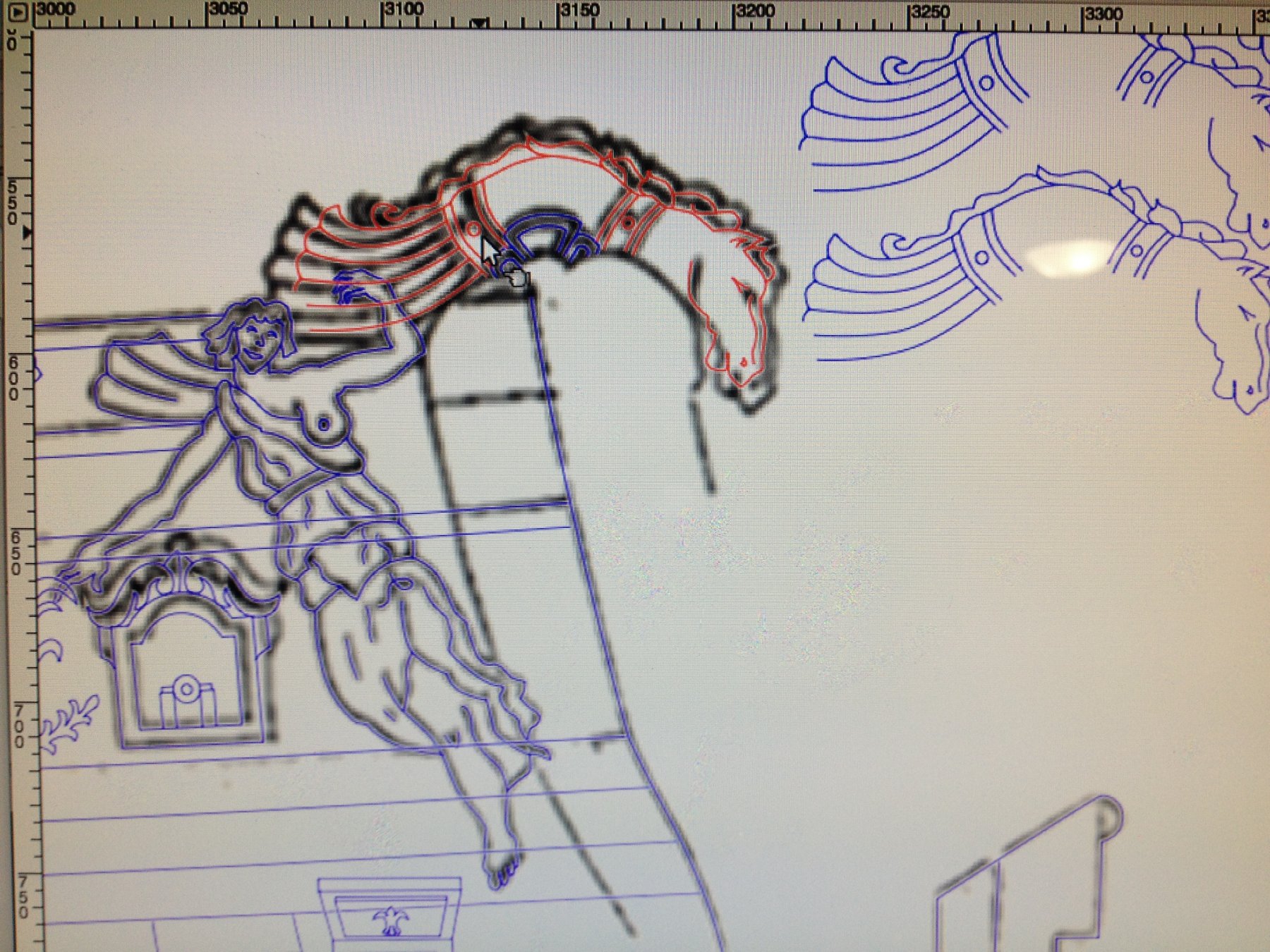
This will be my Derby themed entry:
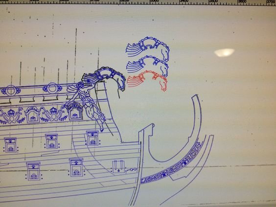
The winner of my re-scaling derby is the red horse, on the outside track! A copy of him has also been placed above the headrail escutcheon, where it is more apparent how the decreases in scaling affect the overall appearance and position of the horse carving. The middle horse was an intermediate re-scaling effort, and the top horse is just a copy of my original path tracing.
It doesn't seem like much, but the heavy 1/32" I gained between the bridge of the horse's nose and where the cathead timber projects will probably be enough clearance to make the whole thing fit seamlessly, while providing (IMO) a better, more streamlined interpretation of the original Berain/Compardel rendering. The reason this works is that there is actually a solid 1/8" of clear passage between the headrail escutcheon and the cathead timber. That space is increased, slightly, by the longer-bias distance that the horse head carving can project from the escutcheon before it hits the cathead. If need be, I can cheat the headrails back a good 1/32", without it being apparent. Fortunately, I still have the first SR I built all those years ago - against which I can see these relationships and take measurements.
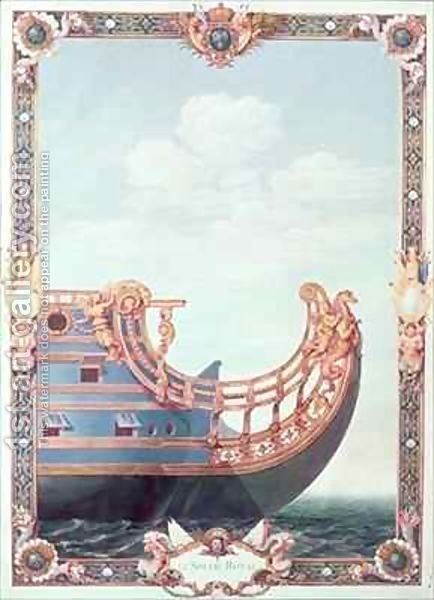
Here's a shot of the original drawing:
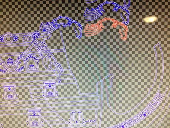
Here's a shot of the rendering without the background. This doesn't show up so well, without the white background, but it is a little less cluttered without the black line drawing that is the original tracing layer. In any case, I think the lower profile horse is more in keeping with Berain's intent. The headrail escutcheons are different, so necessarily, my horse is a little more elongated, but I can live with it.
Alright, one last picture that sucks a little less than the others:

I'll still need to edit the Roman tunic so that it re-connects with the angel figure, but I am tired and have had enough for the night.
- CaptainSteve, Archi, Vivian Galad and 2 others
-
5
-
Great observation, Dan, regarding the arched main deck ports. This is how Heller has moulded them, so that the port sills run parallell with the wale strake just beneath them.
With regard to the cathead timbers, you have brought my attention to a bit of a design problem; a problem, whereby the standard kit architecture isn't going to allow me to simply add this horsehead detail, as it's currently drawn.
Because I was planning to use the kit headrails (a nice detail of the Heller kit that would be difficult to improve upon, from scratch), I had not bothered to draw them in. I have simply suggested the top edge of the headrail escutcheon, as it relates to the horsehead.
The Berain drawing/Compardel Painting of the bow, show the cathead timbers extending out, just forward of the bridge of the horse's snout.
The following link takes you to a nice waterline model of the Heller kit, which shows pretty clearly the standard relationship of the cathead timbers to the headrail:
As I've drawn it, the cathead timber would want to run through the horse's snout, in order to be properly supported by the cathead knee. I'll have to take some measurements to see what sort of clearance I have. Perhaps, i can just re-scale the drawing of the horsehead a little bit, but more than likely I will have to redraw it altogether, if I want to keep this detail.
- EJ_L, CaptainSteve and vossiewulf
-
3
-
Great work on the interior, EJ! One thought that occurs to me has to do with the "dreaded sanding phase". Naturally, there will be a ton of dust. What is your plan for making these interior compartments, at least temporarily airtight, so that they don't fill up with dust?
- popeye the sailor, EJ_L and Eddie
-
3
-
In the following series of pictures, you can see that the armament is now fully in place. This enabled me to correct a few positional errors in the quarter deck cap rails. There is some overlapping of detail on one of the ornamental end caps, as it overlays the plank scallop detail, but some of that scallop detail will remain visible, and as can be seen in Berain's black and white drawing - where certain details overlap, the dominant detail seems to prevail; in this case, the end cap ornament is the dominant detail and so it will not be reduced.
I still have not corrected the problem of overlapping lines, where paths intersect and certain path objects are intended for the foreground and others for the background. I suspect this has something to do with the fact that I have not yet "stroked" the paths, but I am going to make a test copy of the document soon, in order to test out a few different ideas about how to solve this problem.
I drew in a lower port accent for the main deck ports, which will be affixed to the wale strake just beneath the ports. I've omitted this new detail, in the areas reserved for where I am going to re-locate the main and fore channels.
The location of the waist ladder is one port aft of where it appears on the model. This gives me better visual balance, relative to the vertical skid timbers that are evenly spaced, just forward of the ladder. Also in place, now, are the scupper ports on the lower and middle deck levels.
Here, one can see the protective anchor sweep, and just forward of that on the lower battery, I've drawn in a 15th "hunting port." The first Soleil Royal was pierced (along with La Reyne, before her) with 16 ports on the first battery. While my inclusion of this forward-most port still leaves me one shy of her actual first battery piercing, it is still one port closer to accuracy than the Tanneron model, which is pierced for 14. I am told that, in practice, this forward most port would not - for the most part - have been armed, except when in chase, the next gun aft would be shifted to this forward pointing port.
Again, including this detail is a good example of an attempt on my part to create a better impression of accuracy; although, of course, if one counts the ports they will realize that one port is missing. I haven't decided whether I will simply scribe in the port detail and add hinge strapping, hinge barrels and a ring bolt, or if I will actually cut in the port.
The spacing between the anchor sweep and the hawser detail is tight, but workable, and in reality, a little less congested than I've drawn it. I'm just not good enough with the software to properly depict the foreshortening of the bows and how the hawse holes should appear in plan view.
Next, I'll fill in all the railing detail and then I'll start filling in the quarter galleries and the frieze details. I realize that this is all incredibly tedious, on my part, but I find it helpful to see exactly how the arrangement of details falls in relation to each other. I can now see, for example, that my window surround, just forward of the quarter gallery, will need to be simplified quite a bit.
- CaptainSteve, EJ_L, vossiewulf and 1 other
-
4
-
Hi E.J.,
Is that a mast plate I see at the base of the foremast? If so, was thst stock or an add-on. I ask because I often wonder what I will do when it is time to step masts. On such a big ship, a re-enforcing mast plate makes sense to me. Or would mast-partner (I think they are called?) wedges be adequate. Curious what your thoughts are on this issue.
-
-
Ah, yes - I think you are right about that! That would make sense. Thanks, Vossie.
- EJ_L and vossiewulf
-
2
-
Thank you for the comment, EJ. You raise a good question. This antler carving is one that I was hoping to keep without altering it or re-creating it. It's one of the details that the Heller kit really does well. Although it differs from the Berain drawing of this detail, in some ways I think it is a more elegant execution. In truth, my hand-drawing does not completely accurately mimic the lines of the antler details. As moulded, they take up even less space between the ports than my drawing shows. Try as I might, I just could not get the lay of the line right on those, but because I wasn't planning to re-create it - good enough really seemed adequate for the purpose of assessing the total layout.
What I may have to do is slightly alter the leafy scrolls of the port enhancements, here and there, wherever they encroach too much on the antler things. For the most part, though, I don't think these two details will interfere with each other.
- CaptainSteve, mtaylor and EJ_L
-
3
-
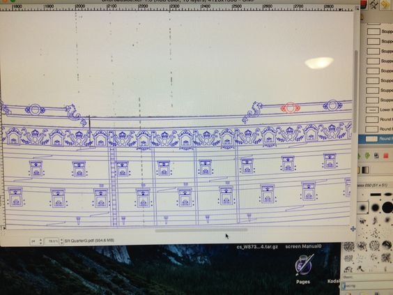
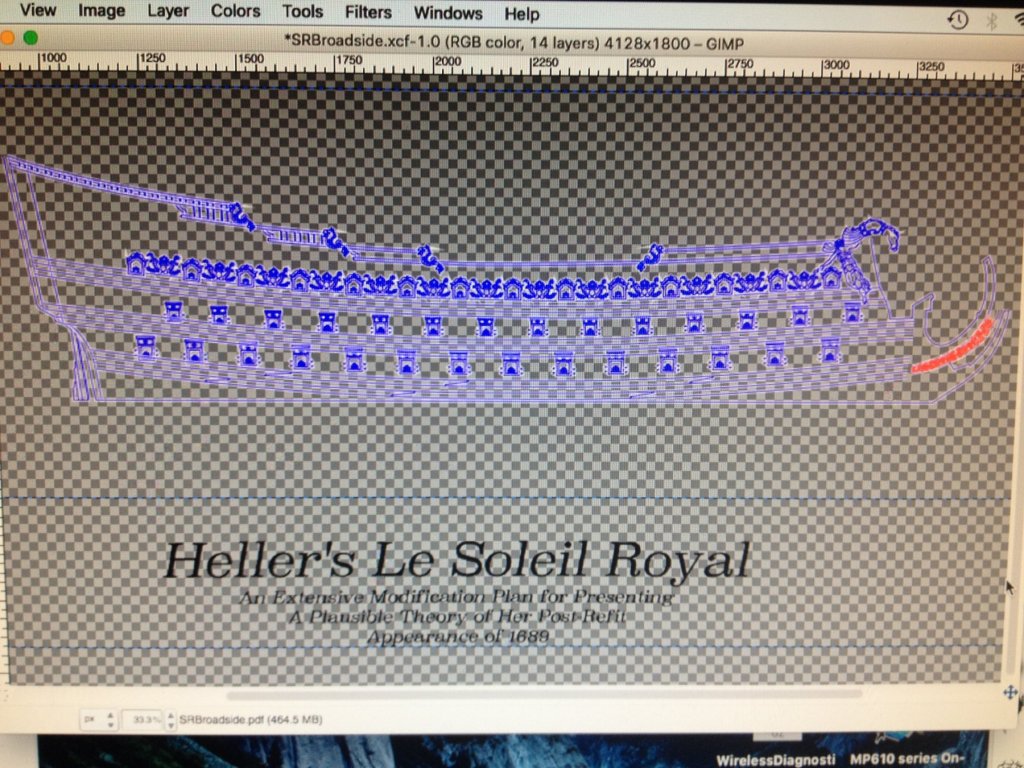
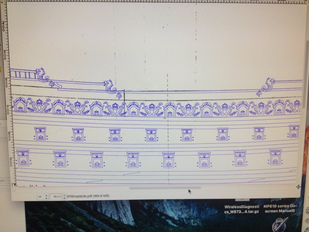
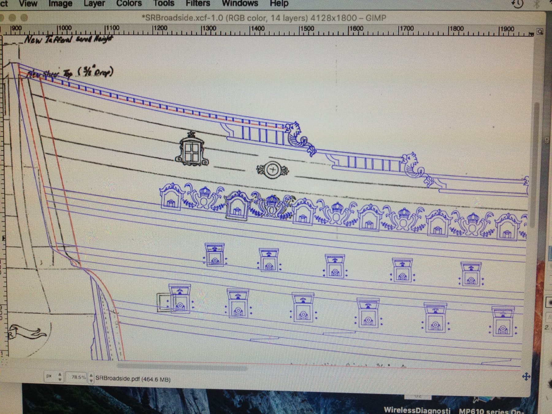
Sometimes I worry that the forum moderators will close my build-log, if they don't see any signs of activity. With that in mind - this post is something of a place marker, but it does illustrate progress on the drawing and highlights a few of the areas where designing to fit within the kit architecture presents specific challenges and/or limitations.
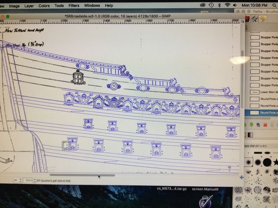
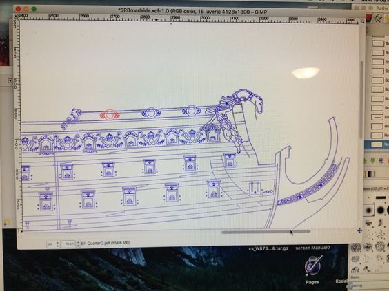
This is my work area in Gimp. For this picture, I've hidden the white background tracing layer, which is my digitized hand-drawing. With the main wales located, and the first three batteries in place, and properly located, she is beginning to look like a ship of war. With the water line raised and the sheer line reduced, slightly, I think she sits pretty in the water:
The next three pics have the tracing layer visible, and I've scaled the zoom to accurately reflect the size of the actual kit. This first shot of the bow shows the difficulty of designing the filligree between the knees of the head; rather than a parallel space between the knees, the space widens as you move outboard from the stem. This means that the elements that make up the filligree can't simply be drawn once and copied, but must be drawn individually to fit. The "X" shaped bits are supposed to frame shell carvings (which I may not model at this scale because the detail would be so tiny), are placed to correspond with the vertical ballusters that unify the three rows of headrails:
The arched, main deck ports also presented unique challenges that were not readily apparent until they were duplicated and placed along the upper bulwark.
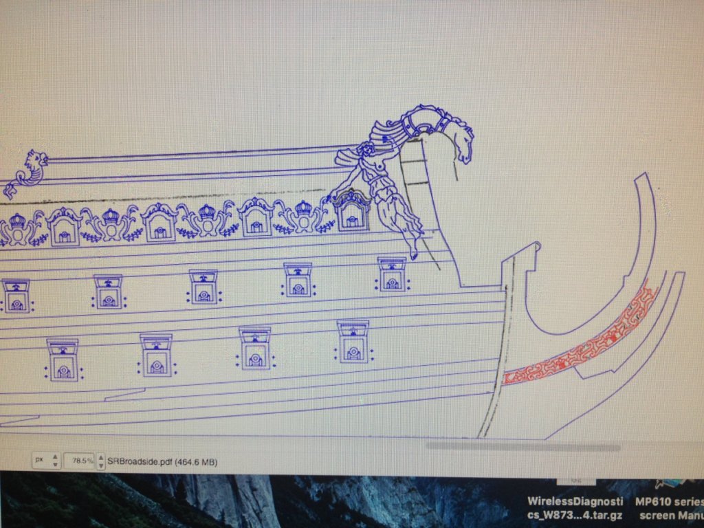
First, my hand drawing did not accurately reflect the height and width of the actual ports; I drew them about a 1/16" too tall and almost a 1/16" too wide. However, the space they can fit into, along the upper bulwark, is tallest aft and tapers to a more narrow space in the forecastle. When you factor in that I also, initially, exaggerated the domed arch, and you add on the scrolled port enhancement, then the whole thing becomes really crowded, among the antler escutcheon carvings (not sure what else to call them):
I had to re-draw the port several times, duplicate it and place the row of ports until I was satisfied that the composition did not look too cluttered. I have yet to correct the bow angel's extended hand, which no longer rests upon the smaller port, but I will do so soon.
Now, while the whole thing is very busy looking, when I consider the Compardel drawing upon which these port enhancements are based - then I think that my layout is actually better balanced and less cluttered looking. This has to do with the fact that the Berain (black and white) and Compardel drawings of the stern quarters reflect a more exaggerated sheer of the wales, as it intersects with a less pronounced sheer of the actual gundecks; the wales, the ornamentation and everything else outside the ship appear to rise rather sharply, while the gun ports, themselves, cut more steeply into the wales than is shown on the Heller kit.
I have tried unsuccessfully, just now, to post a sketch of The Monarch of 1668, which illustrates quite nicely this more pronounced sheer of the wales, on a ship of the First Marine. You can see that the aft-most ports cut completely through the wale. I will post this pic later, from my home computer, where it is easier to do so.
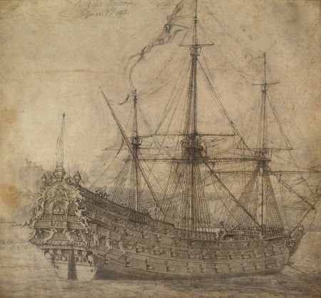
The reason for this variance has to do with the fact that the Heller kit, and the Tanneron model upon which it is based, reflect latter 17th C. Architecture of the Second marine - namely, the Foudroyant of 1693. This fundamental difference between what I am trying to represent with the first Soleil Royal and the inherent inability to accurately represent the correct sheer of the wales on the plastic kit drives purists nuts; that, among other architectural inaccuracies. I don't mean for that to be the case, but it is a compromise that I am willing to make because, in the end, I think it results in a less chaotic assemblage of details. I am thinking about adding the leafy port enhancement that is shown beneath the port sills. This would simply be affixed to the wale strake beneath the upper bulwarks, and omitted wherever the re-located main and fore channels make it impossible to include them.
As a related aside, a Belgian modeler named Cedric - whom I mentioned much earlier in this build log - is, in fact, closing off the Heller ports and re-locating them, and the wale locations so that he can more closely model La Reyne. So, to be more clear - it is not impossible. Cedric has already begun by cutting his hull along the same raised waterline I am proposing, sanding away the wales and using the kit port lids to seal off the openings. This promises to be a very visually rewarding project, on his part, and one that I think will be very complementary to what is happening here. I commend Cedric for his effort and attention to detail because what he is doing goes to a level that I am not willing to take my project.
Here is a link to his build-log for La Reyne, where he recently posted an update with pictures:
One can immediately see, in Cedric's pictures, how cutting away the lower hull drastically improves the impression of the hull as a viable sailing ship.
You can begin to see a few of the details that will be added in: scribed scarf joints into the wales at appropriate intervals, and the through-bolting for the carriage tackles. There are a number of other small details, like this, that can be sketched in now, with the gunports in place.
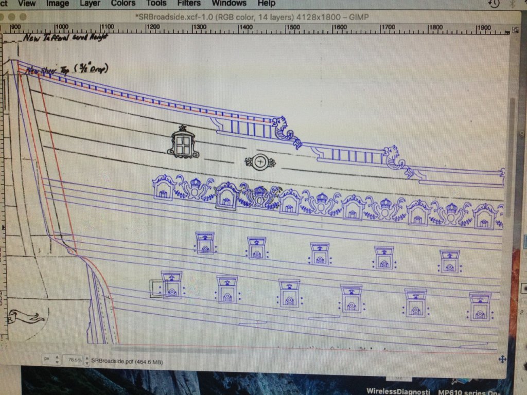
regarding the thin wale strakes that frame the railings of the sheer line - they will be mostly scraped away to make room for the upper bulwark frieze. For now, I'm showing a short, moulded nub beneath the scalloped detail at each step in the sheer. I'm not sure how I will ultimately resolve that, but for now, I like this.
You can see the 1/4" re-location, forward, of the aft most port on the lower deck, that makes a little extra room for the lower finishing of the quarter gallery. I have the tracing layer for the quarter gallery on a separate layer that I am not showing right now. Of course, aspects of the QG are not lining up so neatly with where I would like those transitions to land, so that will require digital manipulation, when I get to that part of the tracing.
High-lighted in red are two parallel lines that (in-board) indicate where the stock kit architecture ends and (out-board) shows the 3/8" extension piece that is necessary to close-in the lower stern walk. The blue line beyond that indicates the round-up of the upper stern, which is probably exaggerated. I will have a better sense for the depth of that when I begin making card templates to offer up to the stern, for patterning of the framing elements.
Finally, while I am cutting away the topmost step of the Heller sheer, I am adding back a lower-profile, continuous rail that extends forward to the rail cap. The reason for doing this, primarily, is that it buys me back a little extra real estate (in-board) for the upper most "poop royal" deck that will have to be lowered, somewhat, and the camber increased, slightly, towards the middle of the deck, in order to work within the reduced sheer. The depth of the deck, fore and aft, will also need to be shortened, somewhat. I haven't drawn any of that, but I know it can be re-worked in a pleasing way.
- CaptainSteve, shipmodel, mtaylor and 2 others
-
5
-
-
-
Good question. I'm not sure what the answer is, but a good starting point might be H.M.S. Victory:
http://www.prdobson.com/album/hms-victory/photo/120/
A little later, I'll reference Goodwin's Englishman of War
-
-
Whichever way you go Ken, it is going to come out well because your work has been so clean, so far. Do whatever you are comfortable with and have fun with it.
- piratepete007 and ken3335
-
2
-
-
I was wondering the same thing, Ken. Your first planking is really nice and clean, but the finished model is immensely improved by following traditional practice. One of the Forum moderators - Chuck - has an excellent series of two videos that describe the layout and spiling of continuous planking using simple math, tools and techniques. Though I'm still a plastics guy, I will be coming back to this when I transition to wood. The learning curve under his tuteledge is a speed-bump instead of a mountain. I will post the thread link.
-
-


HMS ROYAL KATHERINE 1664 by Doris - 1/55 - CARD
in - Build logs for subjects built 1501 - 1750
Posted
On the subject of girdling, I remember reading some time ago that there were problems with the Katherine after her launch, in terms of her handling characteristics. The inclusion of this detail, is a very nice touch, and a subject that one rarely ever considers when thinking about ship models.