


SardonicMeow
-
Posts
222 -
Joined
-
Last visited
Content Type
Profiles
Forums
Gallery
Events
Posts posted by SardonicMeow
-
-
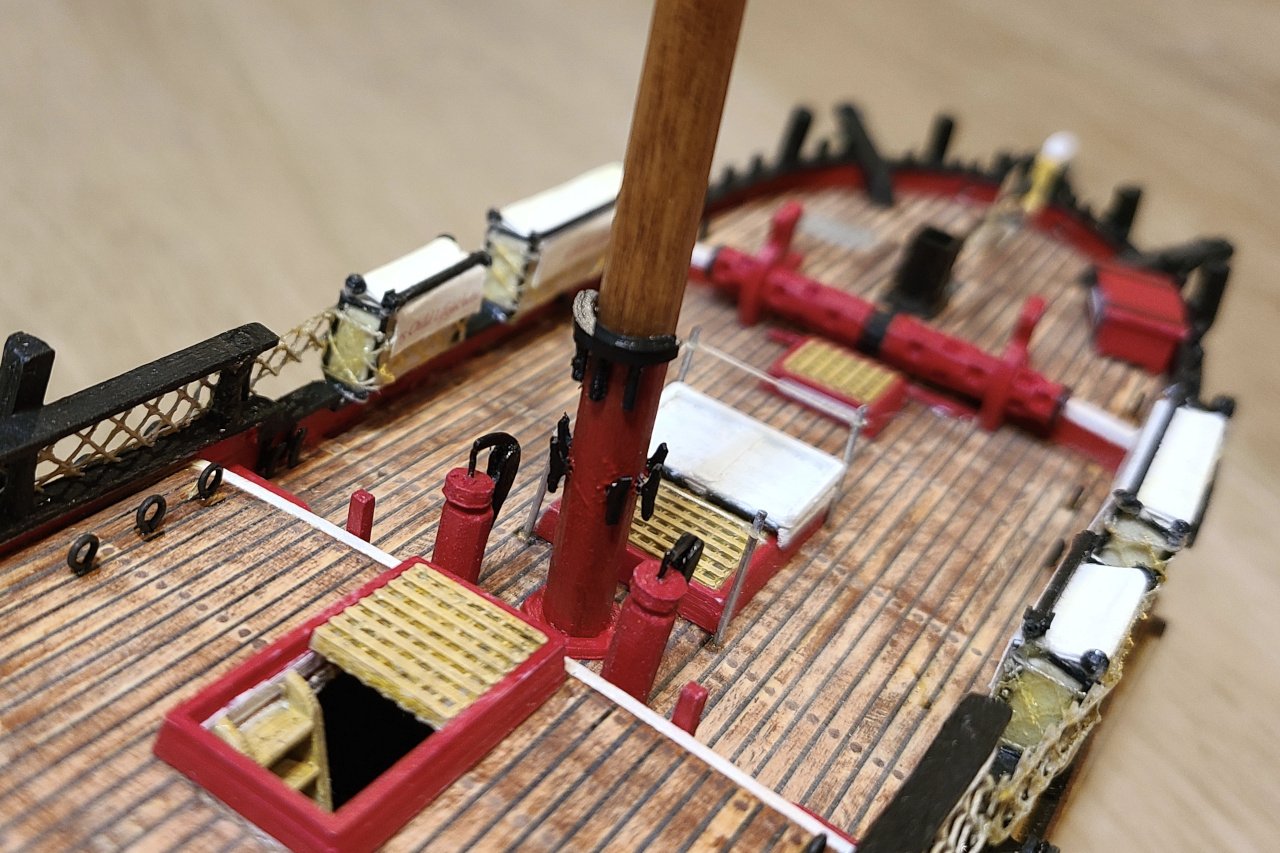
All the cleats have been added to the foremast.
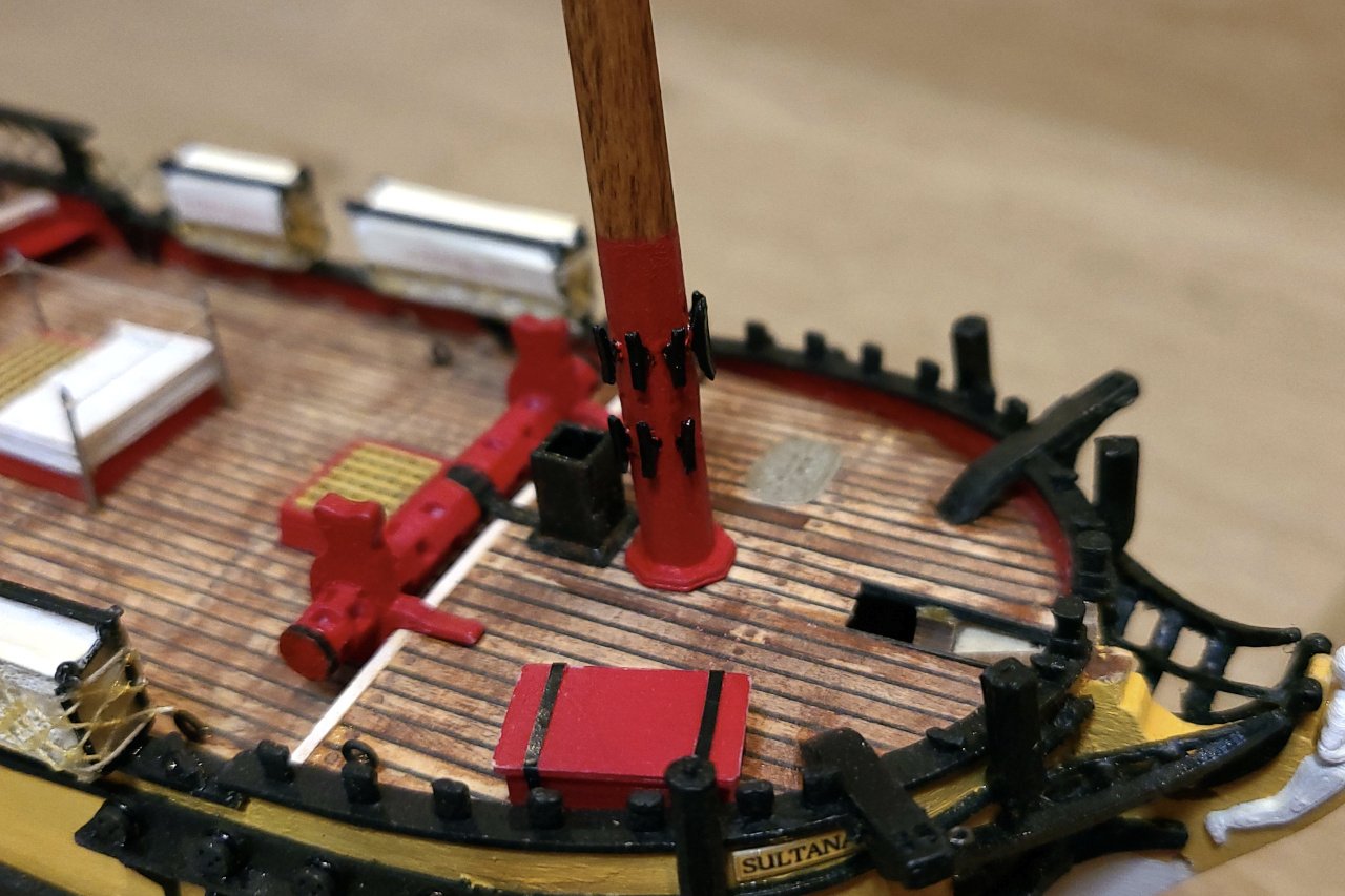
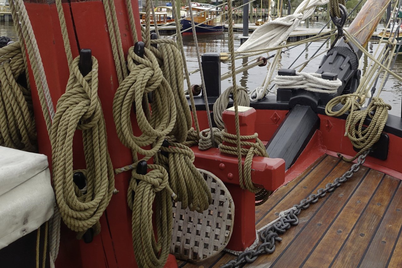
Yes, there really are more cleats on the foremast than the mainmast. They handle the brails, foresail tack, and something else that I don't remember at the moment. The picture below is from my visit to the Sultana in 2018.
The mast hoops were very simple to design.
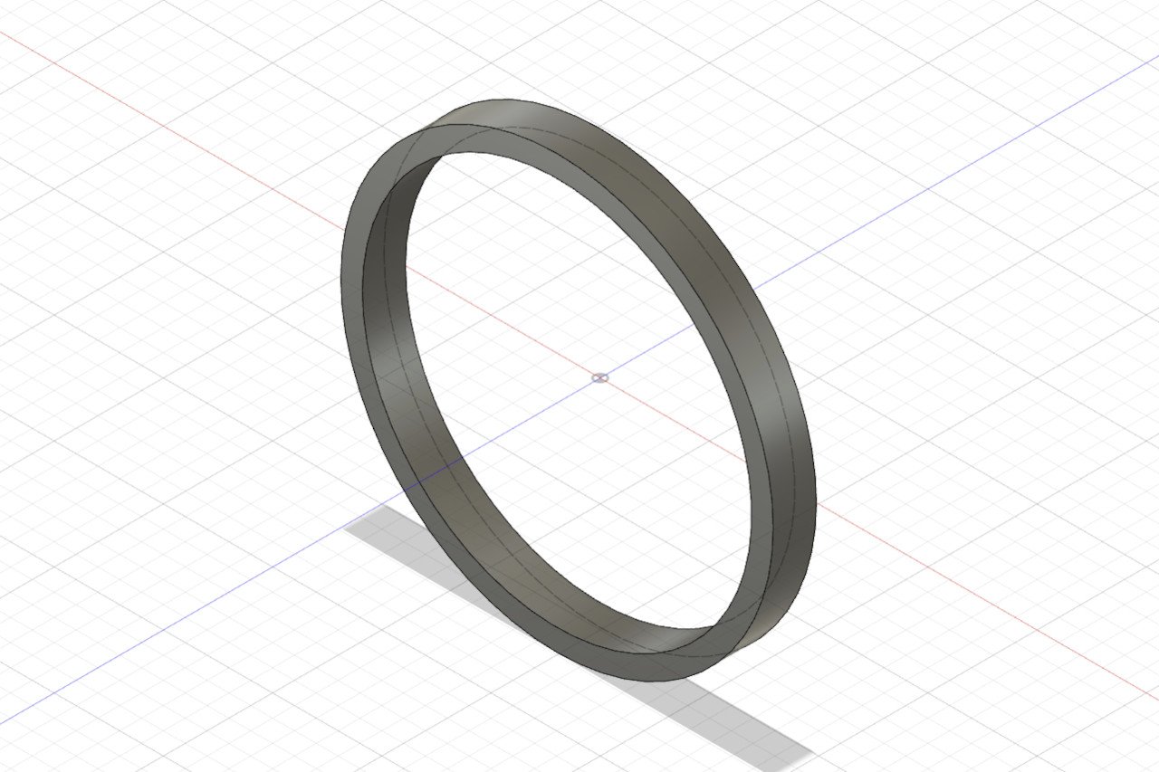
A nice side effect of the 3D printing process is that the filament layers ended up creating a kind of simulated wood grain on the mast hoop pieces. Adding wood stain onto the beige plastic makes them look convincingly wooden.
- Roberto96, Matt D, GrandpaPhil and 1 other
-
 4
4
-
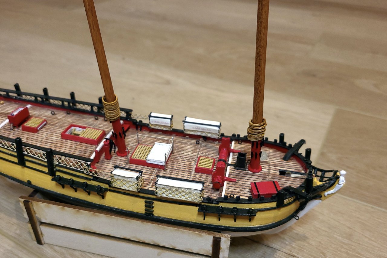
Time for some work on the masts. For the mainmast I need...
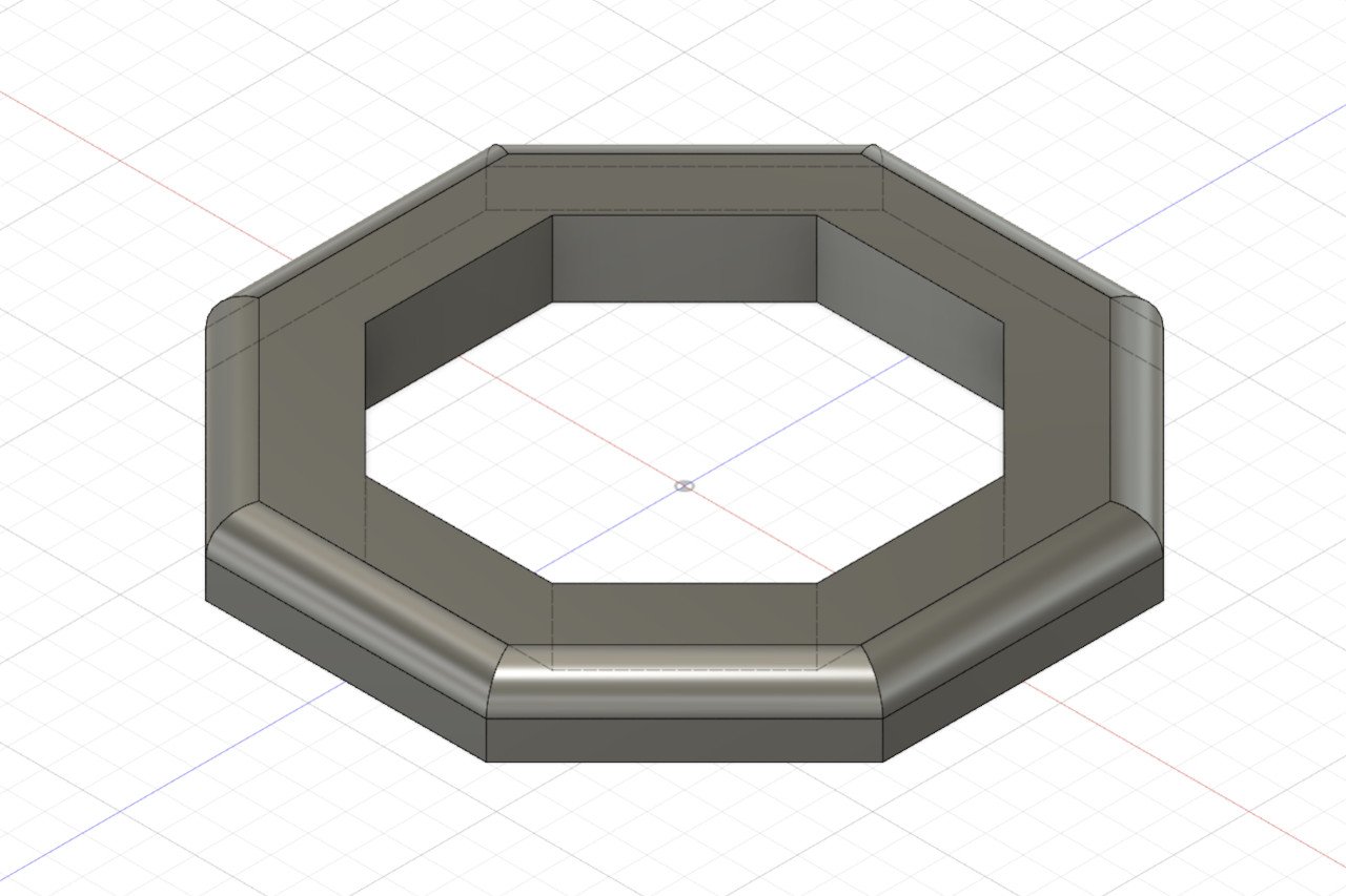
An octagonal thing at the base.
And some cleats.
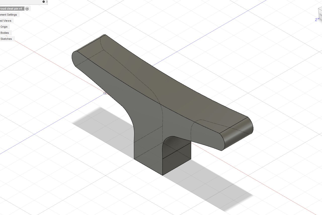
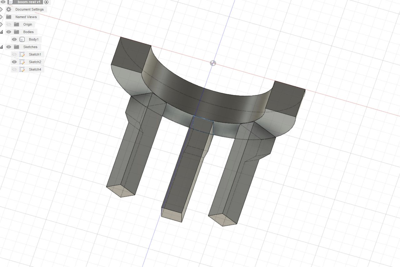
And the boom rest.
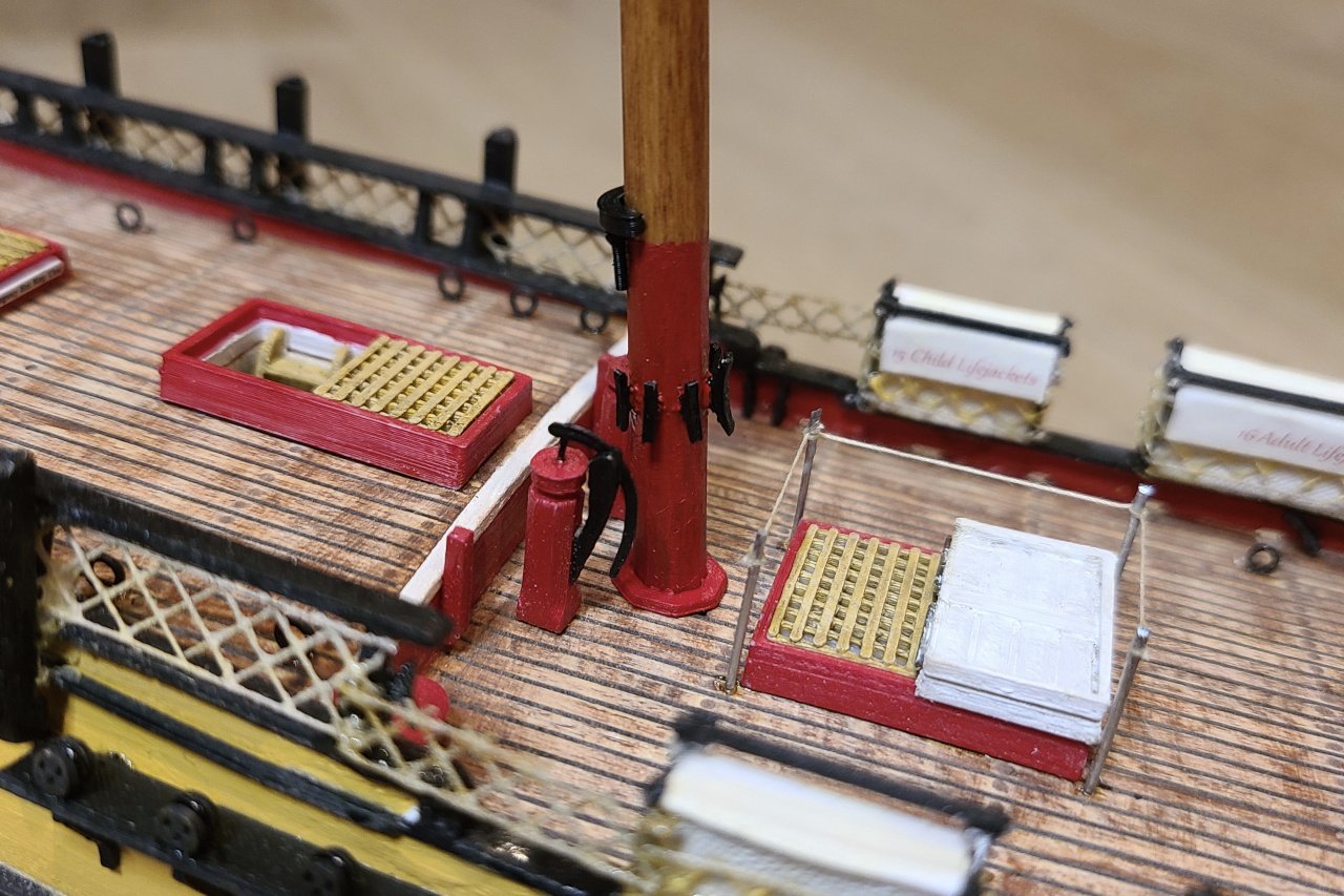
The mast was shaped, stained, and painted red at the bottom. The parts from above were 3D printed in black and glued on. Here is the base of the mast dry-fitted.
I did similar work on the foremast but discovered that the cleats were positioned too low, so that will need a redo.
- Roberto96, GrandpaPhil and yvesvidal
-
3
-
Thanks, Matt. I hope you're doing well too. I had a look at your Winchelsea build log and it's looking great. You should be proud of your planking effort.
-
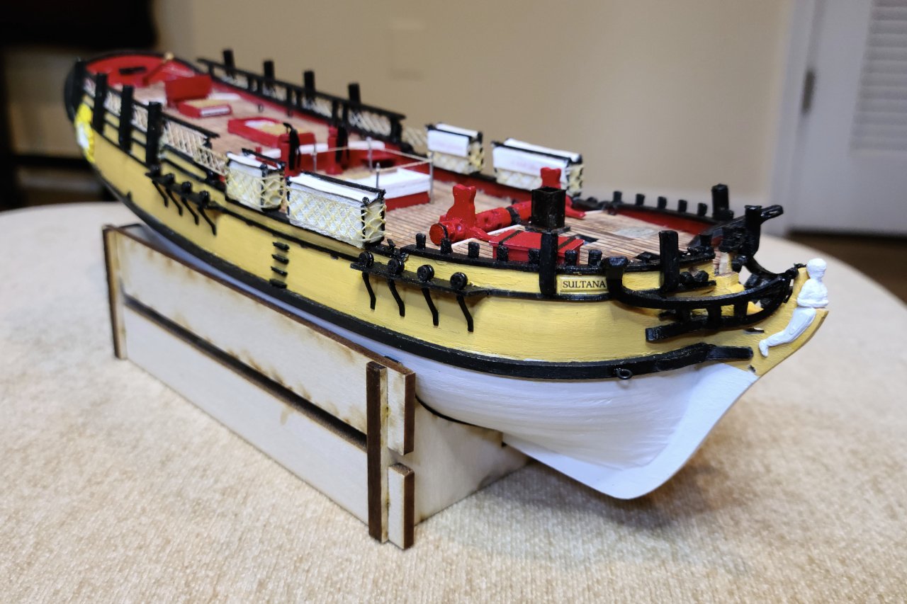
After a little hiatus, I'm back to working on my Sultana. No much progress since my last update, but the lower deadeyes and chainplates have been added.
- yvesvidal, Roberto96, GrandpaPhil and 2 others
-
5
-
I'm impressed by the sails too. The way you made the seams was very effective.
-
14 hours ago, Dr PR said:
So the same hull might show quite different sail rigs from time to time, depending upon the whim of the captain/master/owner, the job to be done, and the size and abilities of the crew.
That's my understanding too. The exact arrangement of sails at any particular time would depend on what the Captain (or, more accurately for a schooner, the Lieutenant) would feel appropriate for the conditions. Topmasts and topsails with their associated yards would be raised and used, or lowered and stored as needed.
-
I'm no expert, but after some searching, I have found that the sail plan strongly resembles that of turn of the century racing yachts. Do some searches on America's Cup winners from the 1890's to 1920's and you see what I mean. The hull shape is completely wrong for a racing yacht, however.
- mtaylor and Keith Black
-
2
-
On 4/4/2020 at 12:50 AM, EricWilliamMarshall said:
I dyed the white string for the rigging darker as per the brief instructions. Not as dark as could be, but given the limited color selection in house due to virus lockdown, I’ll take it.
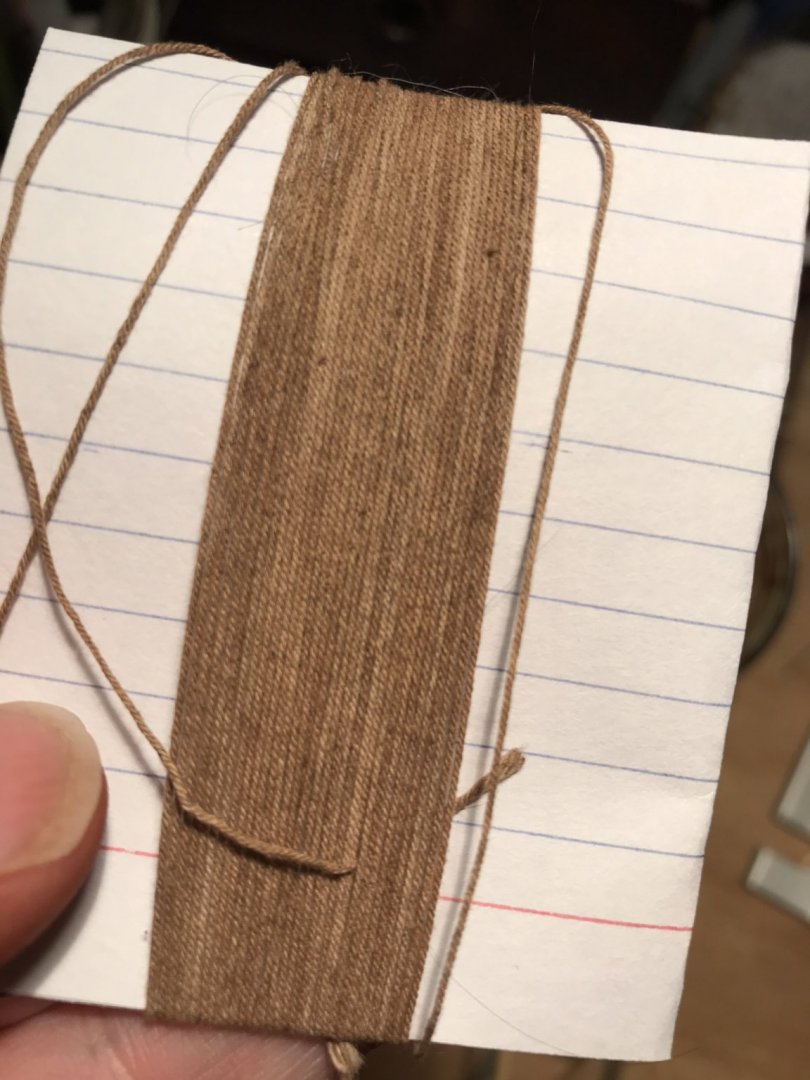
I like how the subtle variations in color make it look more natural.
- coxswain and thibaultron
-
2
-
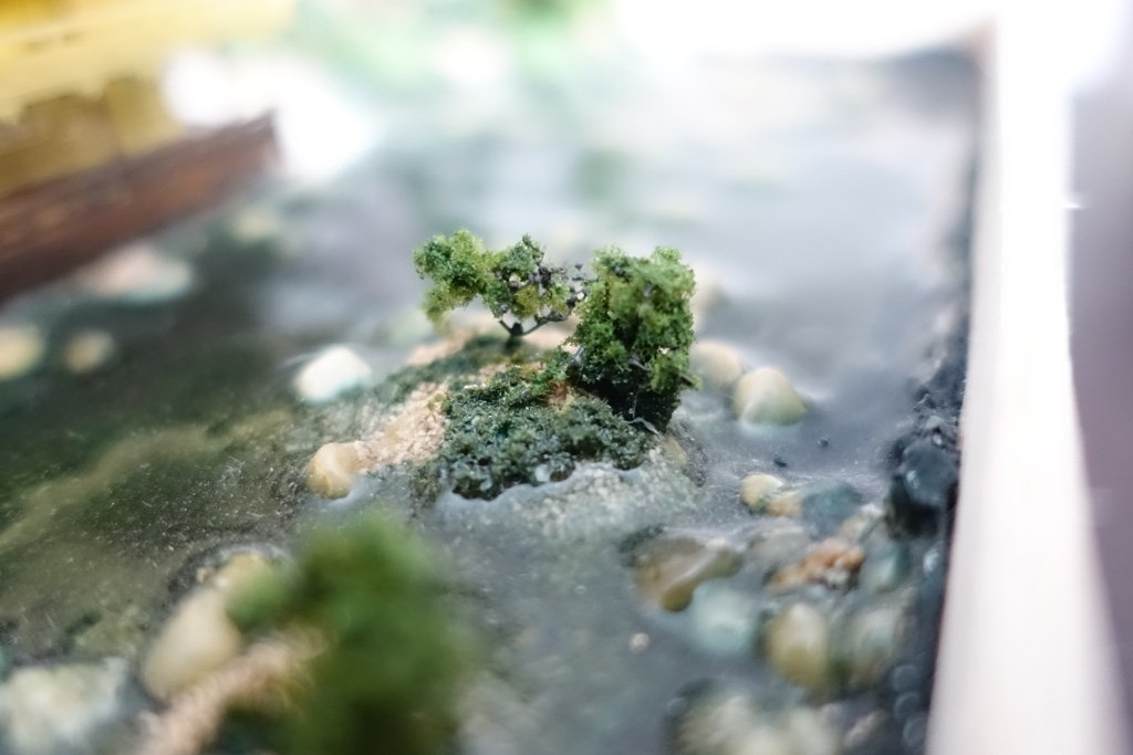
I have only one experience with adding water to a diorama, but I'll share my experience with you. I made this diorama of Kinkakuji, the Temple of the Golden Pavilion, a few years ago. The water is Woodland Scenics Realistic Water, tinted with acrylic paint. Realistic Water can only be poured in 1/8" layers, but it looks like Woodland Scenics has some newer products that can do deeper pours. I needed to do this one in several layers.
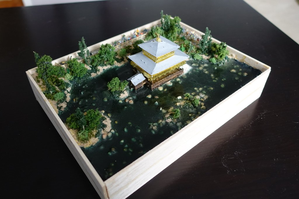
There were bubbles, but I was able to pop them with a pin while wet, so they weren't a big problem.
The biggest issue was how the water would creep up the terrain. You can see it in the picture below, how the water creeps up the island and the blue color has soaked into some of the scenery. It's also visible around all the edges in the picture above. I had to backfill some dirt materal on top to try to mitigate it, but it covers over any nice land to water transition I wanted. So, I encourage you to do some test pours with actual terrain like what you will use in your final display. I just did test pours into a paper cup with some gravel, which wasn't an adequate test.
Anyway, for some great examples on making terrain and water features, I highly recommend Luke Towan's channel on Youtube, in particular the Realistic Scenery playlist.
Good luck with your display!
- BobG, Canute, EricWilliamMarshall and 3 others
-
6
-
27 minutes ago, Beef Wellington said:
an ensign is flown from the ensign staff only while not underway either in harbor or at anchor
Not a historical example, but that's the way it is on the Sultana replica. Here is a picture on the Sultana Projects Flickr showing the ensign staff. Note that the staff is offset to starboard so that the boom can remain at the center line. When the mainsail is raised, the flag is moved to the gaff peak and the staff slides completely out of its holder.
-
Point, when I laser cut parts for my Sultana, I didn't account for the kerf of the laser. As a consequence, there was a slight bit of wobble when I fit the bulkhead pieces into the false keel. If you plan to laser cut, keep that in mind. I later determined the kerf of the laser I used was .3 mm, but it may be different for you.
For the caprail, if the curve is very slight, you could project the shape of the rail onto a plane and it may be close enough to use.
-
19 hours ago, rwiederrich said:
The jibs and stay sails work fine too.
Rob, how did you keep the staysails suspended horizontally instead of drooping down from gravity? How does the sheet remain taut? Is there hidden wire in there somewhere?
-
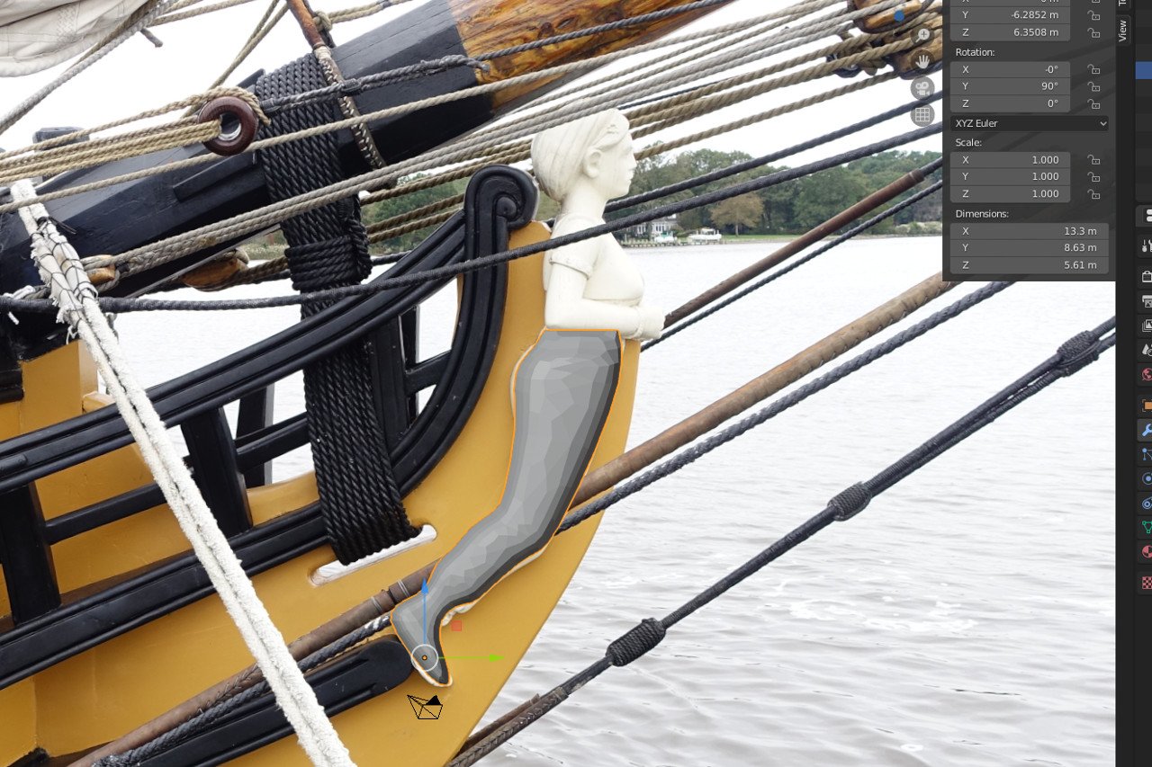
I developed the figurehead in Blender, as I haven't been able to understand how to work in the sculpt environment in Fusion 360.
The legs were relatively easy, just a matter of drawing the outline as they intersect with the plane of the ship's stem. Then I built the rounded form out.
For the head and body, I used the reference images to find contours and borders. Working from those, it was a matter of building the form out, vertex by vertex, face by face.
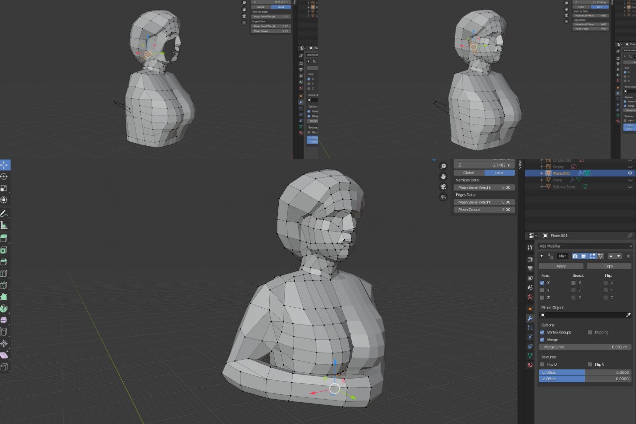
After several restarts, I ended up with the best shape I could.
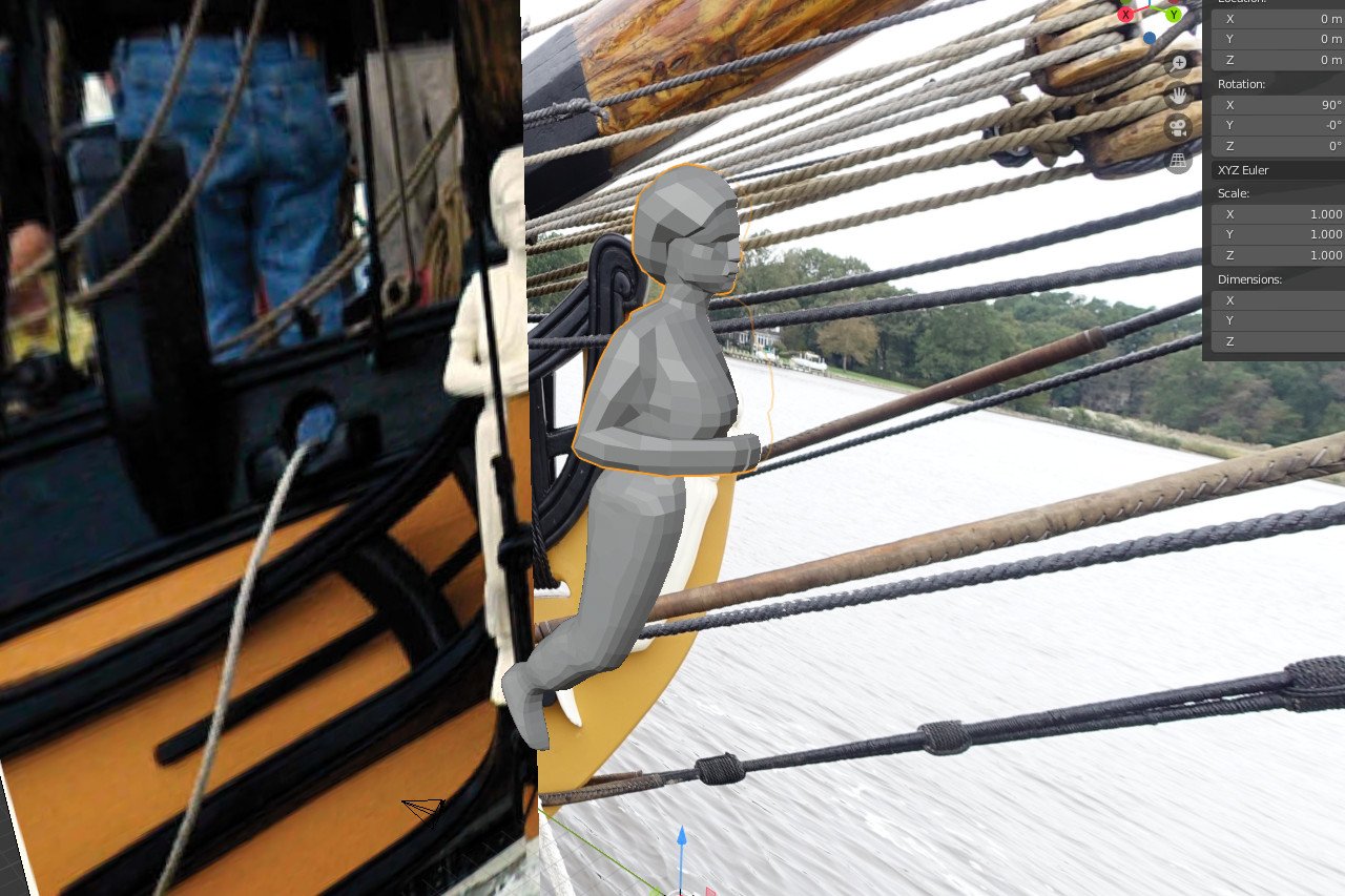
I included the shape of the ship's stem in the 3D environment, to confirm that the figurehead would work with the actual dimensions of the model.
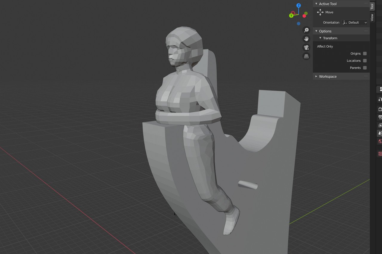
The final 3D printed part was so small that many of the details of the 3D model were lost. Oh well. I painted and glued on the pieces.
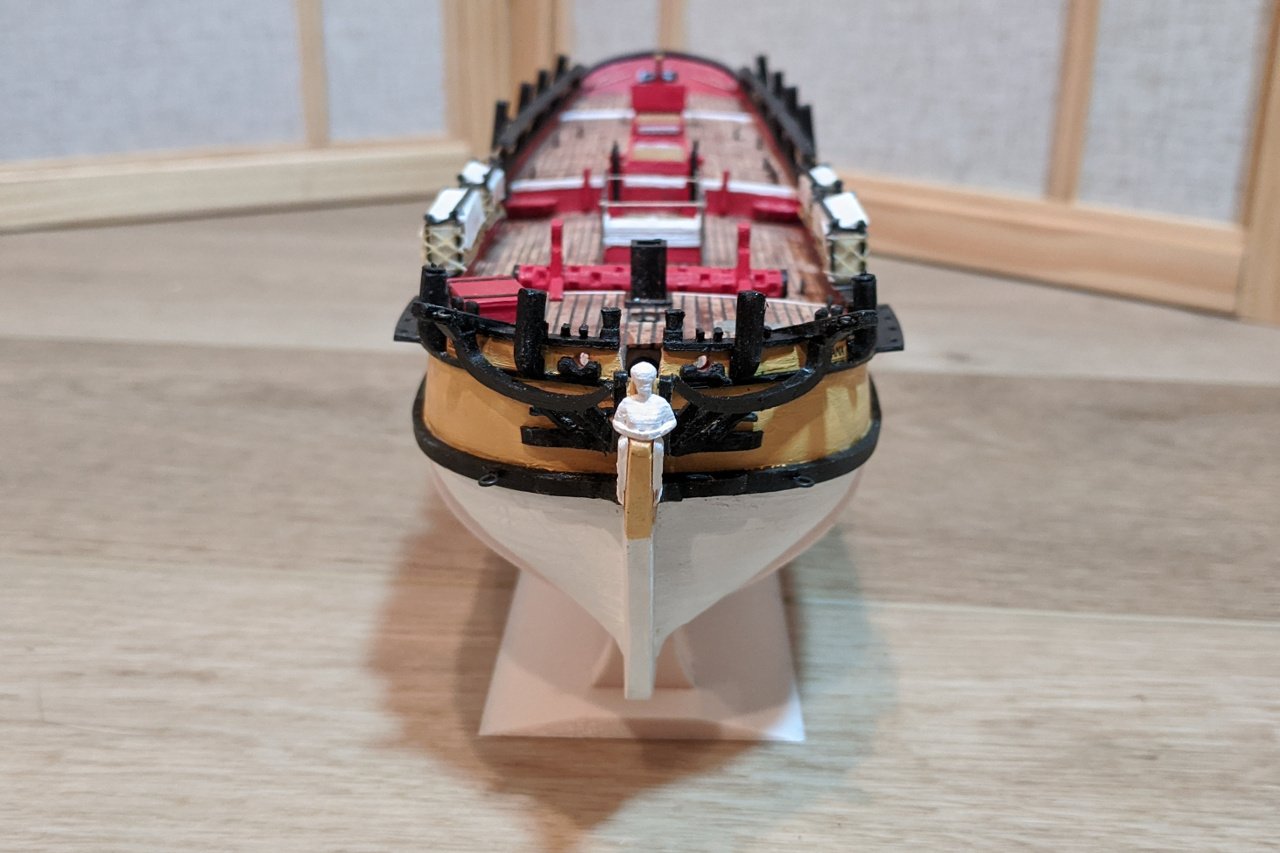
It could be reasonably argued that using carved wood or clay or something else would have produced a better result, but I'm satisfied with my work here.
-
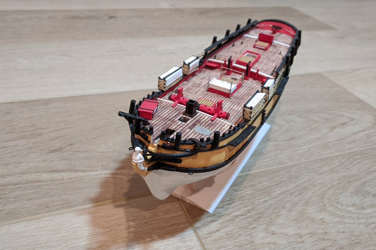
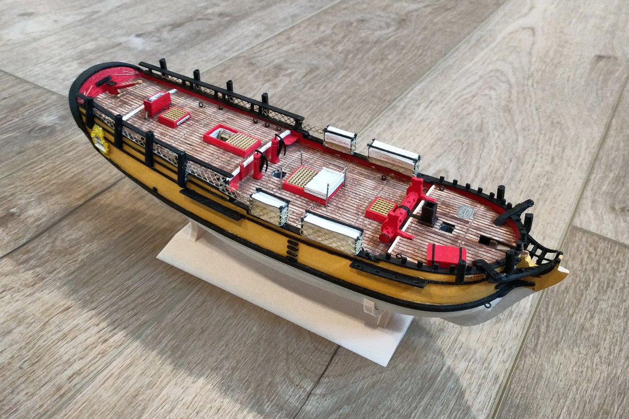
Work on the details of the Sultana's hull is nearly complete. Soon I will be moving on to the masts, spars, and rigging. Here is what the Sultana looks like now.
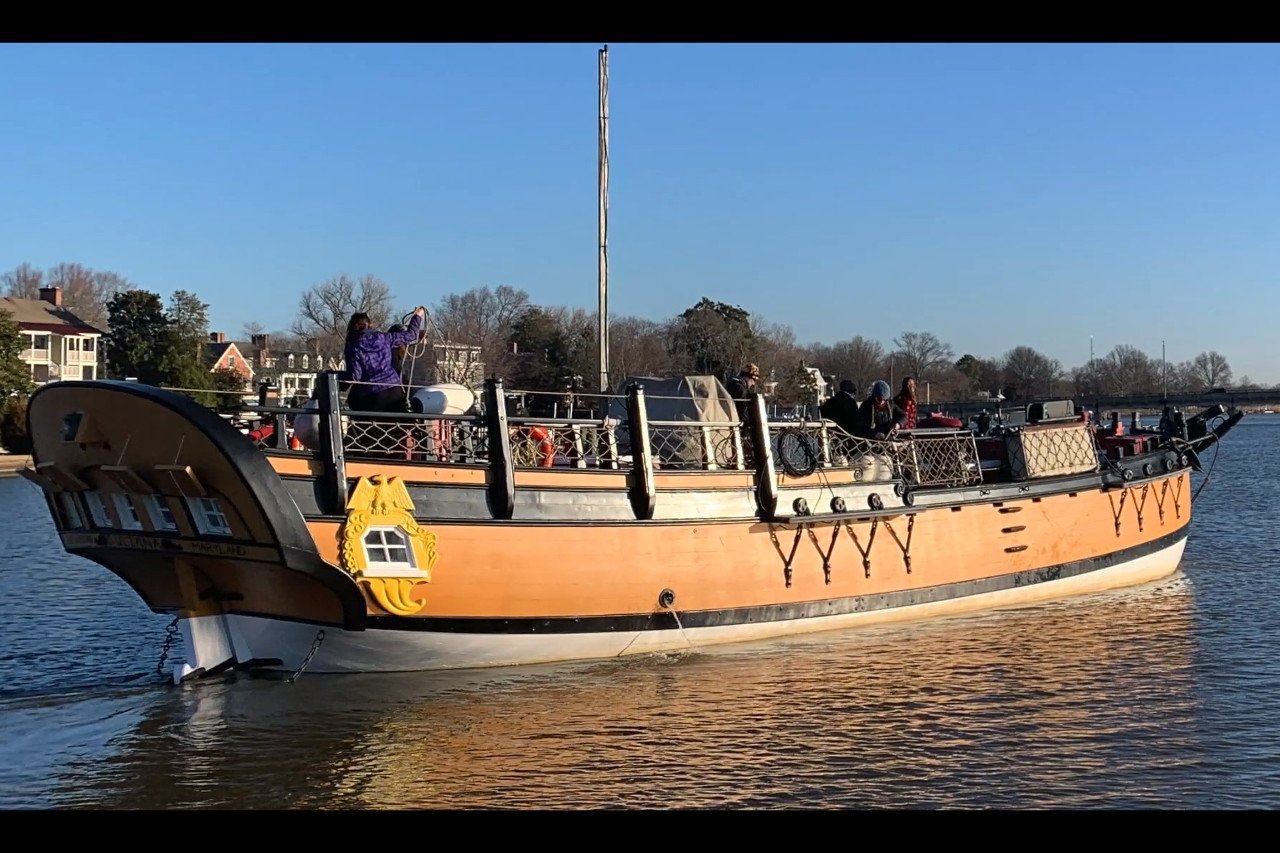
Actually, that's the real Sultana back in December, when her masts were removed for maintenance. The picture is from the video Winter Maintenance on SULTANA’s Masts.
Here is what my Sultana looks like.
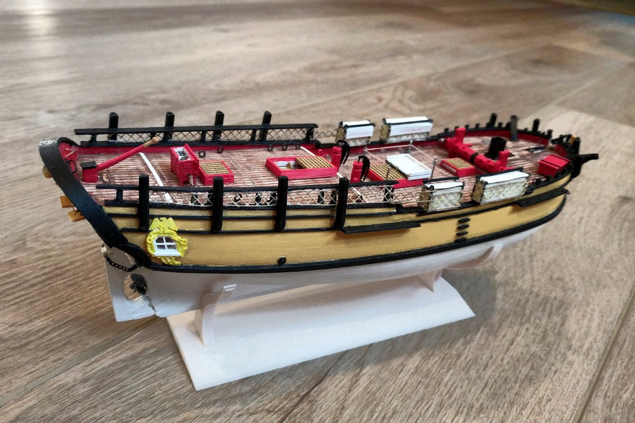
Details that have been added include:
- Rope railing and white cover on the main hatch. I was originally planning to omit these details, but the hatch looked too plain as it was.
- Metal, oval-shaped mystery hatch at the bow, port side. Maybe for refueling?
- Box for storing propane gas at the bow, starboard side.
- Various eyebolts and cleats.
- Additional signage on the hatches and opposite the ladder.
The next steps include understanding and planning out the rigging, and making the figurehead.
- GrandpaPhil, ccoyle, hexnut and 1 other
-
4
-
3 hours ago, malachy said:
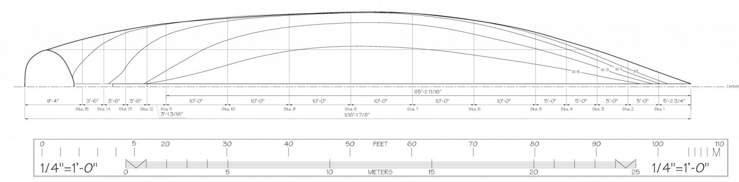
The '50 pixels per feet' probably is just a measurement taken from the original plan in a program like Photoshop or GIMP
Correct. Here is an image from the plans which includes the scale. It goes from 0 to 110 feet. I brought into in a graphics program (I use GIMP) and noted that the 0 mark is at X value 342 and the 100 mark is at X value 5342. 5342 - 342 = 5000 pixels from 0 to 100 feet. Therefore 5000 pixels / 100 feet = 50 pixels/foot. (Your result is likely not to be a nice whole number as in my example.)
-
Are you talking about scaling and positioning plans into the Blender 3D environment? You might be thinking about my post below, where I show my method for doing that. (Note that I was using Blender 2.79, and some elements of the user interface are different in Blender 2.8.)
If you are still unclear on the procedure, I'd be happy to go through it step by step with you here, perhaps using your plan files.
-
1 hour ago, clipper randy said:
can this be done o produce accurate shapes and sizes of masts and yards where the information is known ?
Sure, most anything you can imagine can be designed and 3D printed, but with limitations. For masts and yards on a model, which can be very thin, 3D printed plastic parts will likely flex more than would be acceptable. So for that application, wood is superior. The level of detail possible with a 3D printer is also limited.
That's not to say that 3D printing has no place in ship modeling, as you'll see if you browse through my Sultana build log.
-
Here is my log of playing around with Blender. The first post shows how I imported plans into Blender and scaled them to the scene. I was using Blender 2.79. There are interface differences in Blender 2.8, but the procedure is basically the same, as illustrated in the video Denis posted above.
https://modelshipworld.com/topic/20027-hull-modeling-with-blender/
-
The pumps on the Sultana are quite beautiful, particularly in the long curve of the handles.
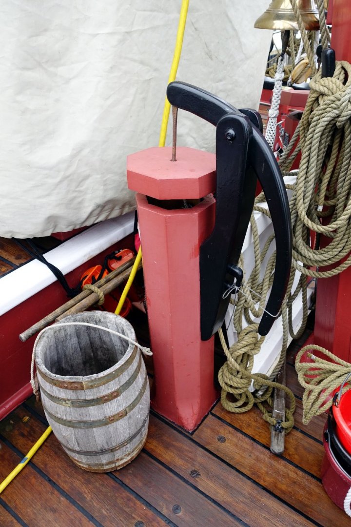
Here is the initial 3D design.
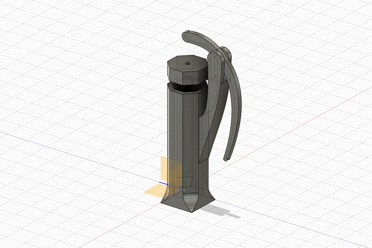
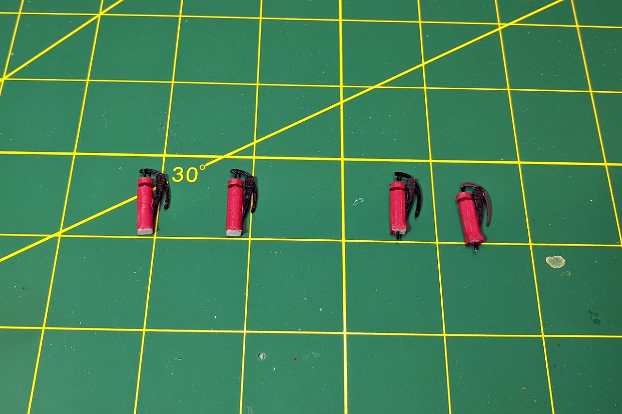
I 3D printed parts, painted them, and tried them out. They were good, but looked a little too tall. Also, the interesting transition from octagon to square at the bottom wasn't distinct enough. I revised my design and created a new set. The old version is on the left, new is on the right. The new pumps also have wire out the bottom to help hold them in place.
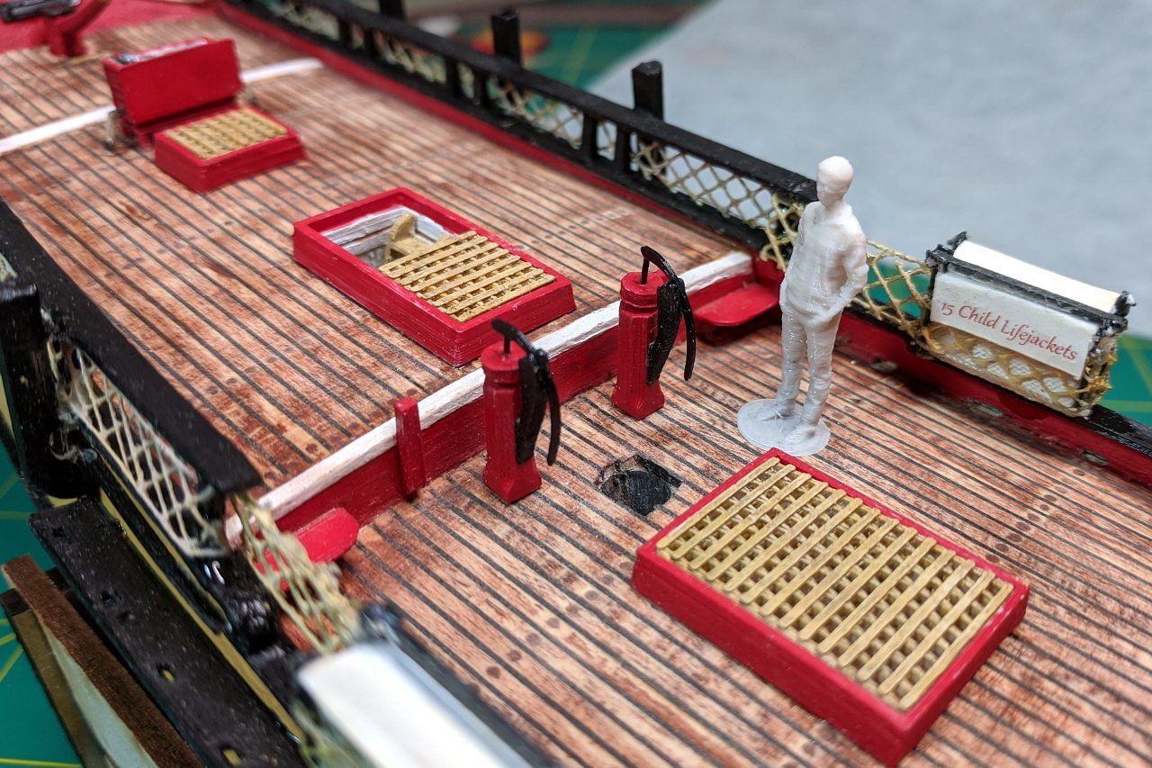
Here are the pumps installed on the deck.
- lmagna, yvesvidal, GrandpaPhil and 2 others
-
5
-
I started work on the binnacle by creating a 3D design with the lid on.
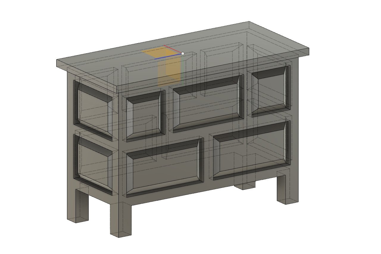
This was not bad, but a bit boring.
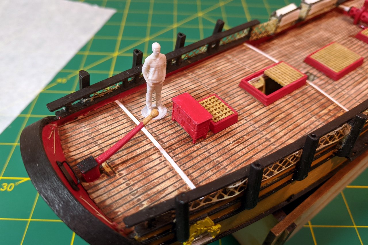
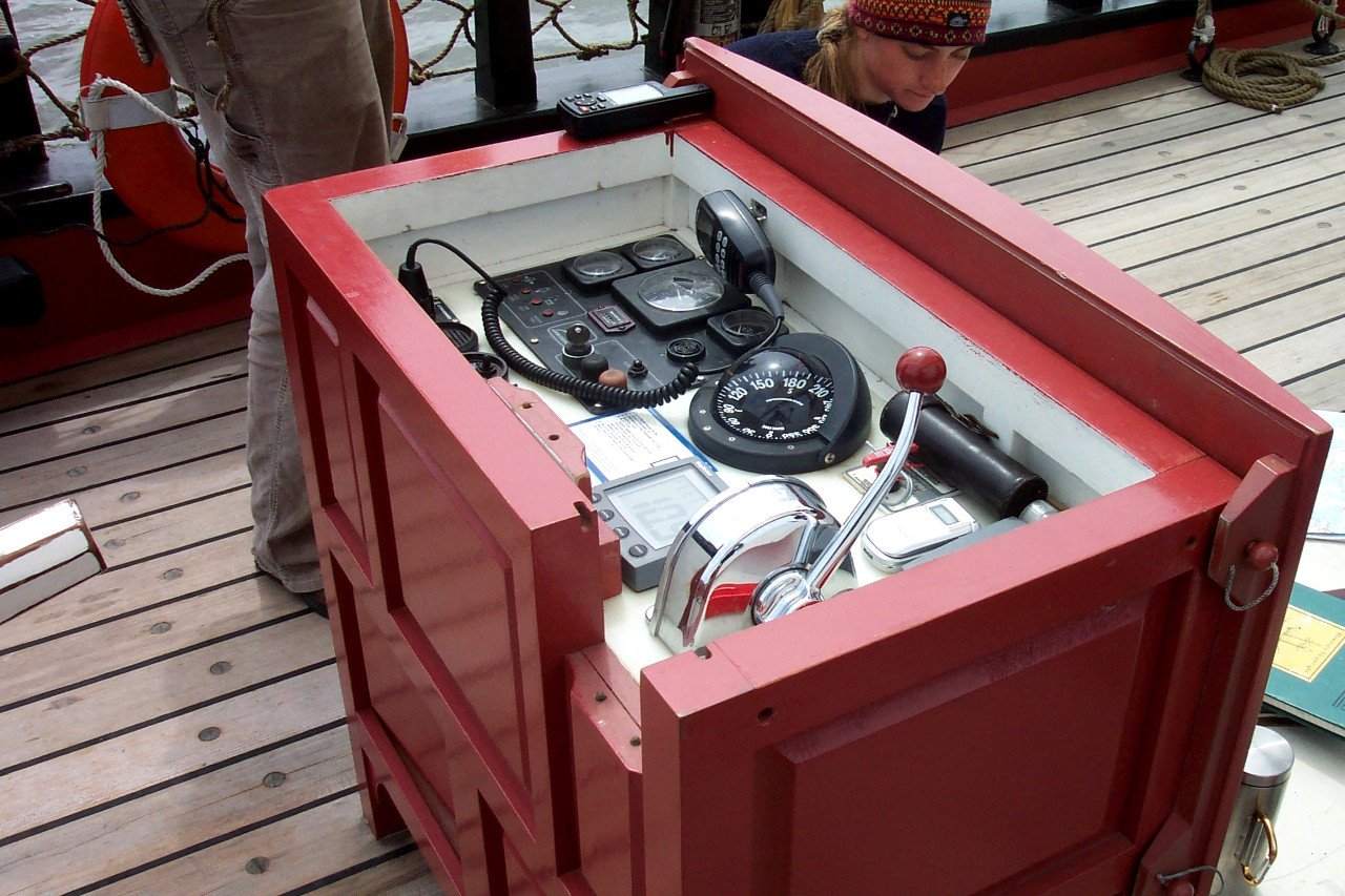
The best picture of the open binnacle I have found is from ship25bsa.smallsquareddesigns.com, which has been a great resource for reference photos.
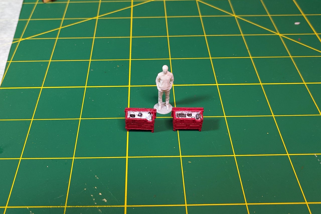
I first tried adding the details of the instruments as raised parts of my 3D design, but it was beyond the ability of my 3D printer to render them in sufficient detail, so the result was just little plastic blobs, which were made worse after painting. My revised design replaced the instruments with a little piece of paper.
Testing the binnacle on the model.
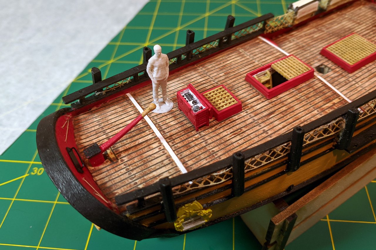
And finally it is glued on and tied down to rings on the deck.
- hexnut, GrandpaPhil, yvesvidal and 2 others
-
5
-
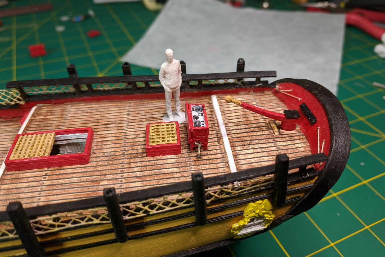
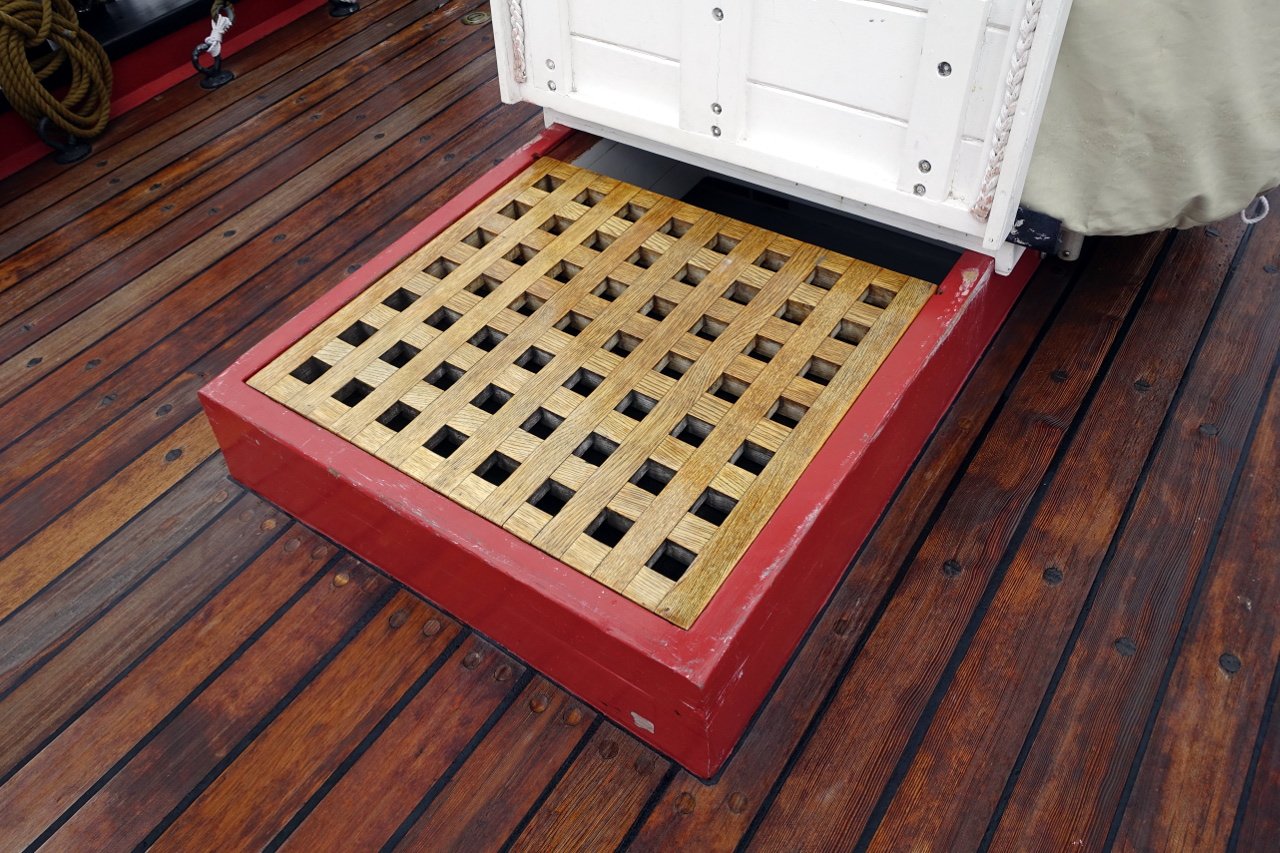
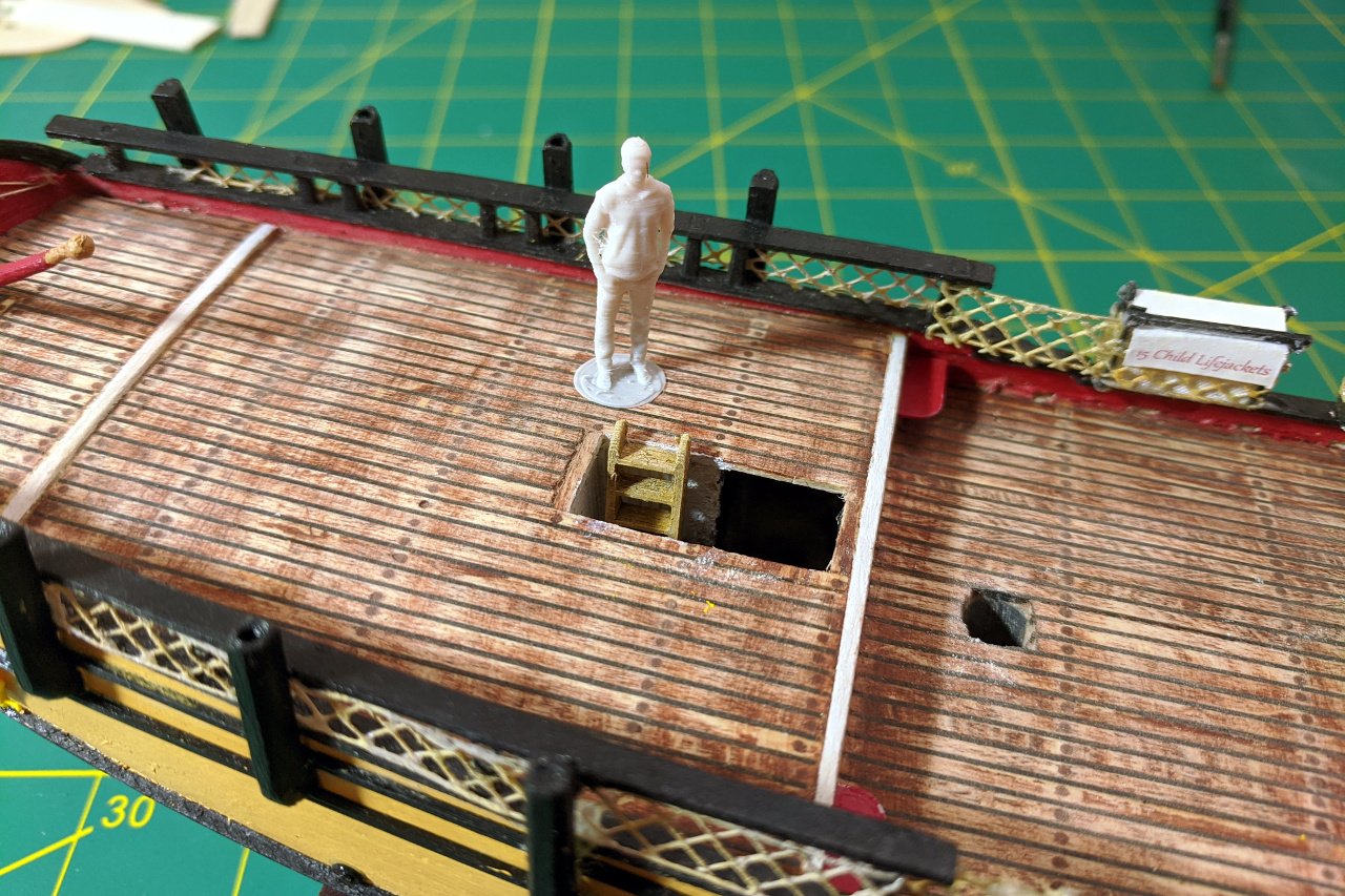
The Sultana has four hatches. Two are small: one is located aft of the windlass and the other is forward of the binnacle. A long, medium sized hatch is on the quarter deck, and will be open to expose the ladder on my model, as it is on other Sultana models. Finally, there is a large hatch on the main deck. Most models depict the main hatch covered with boards, but on the Sultana replica, the large hatch has grating and a ladder down.
The picture below is of the medium hatch, with the grating in place to cover the ladder. Note the white cover. All of the hatches on the Sultana have these covers, which keep out water. However, I think I will omit the white covers.
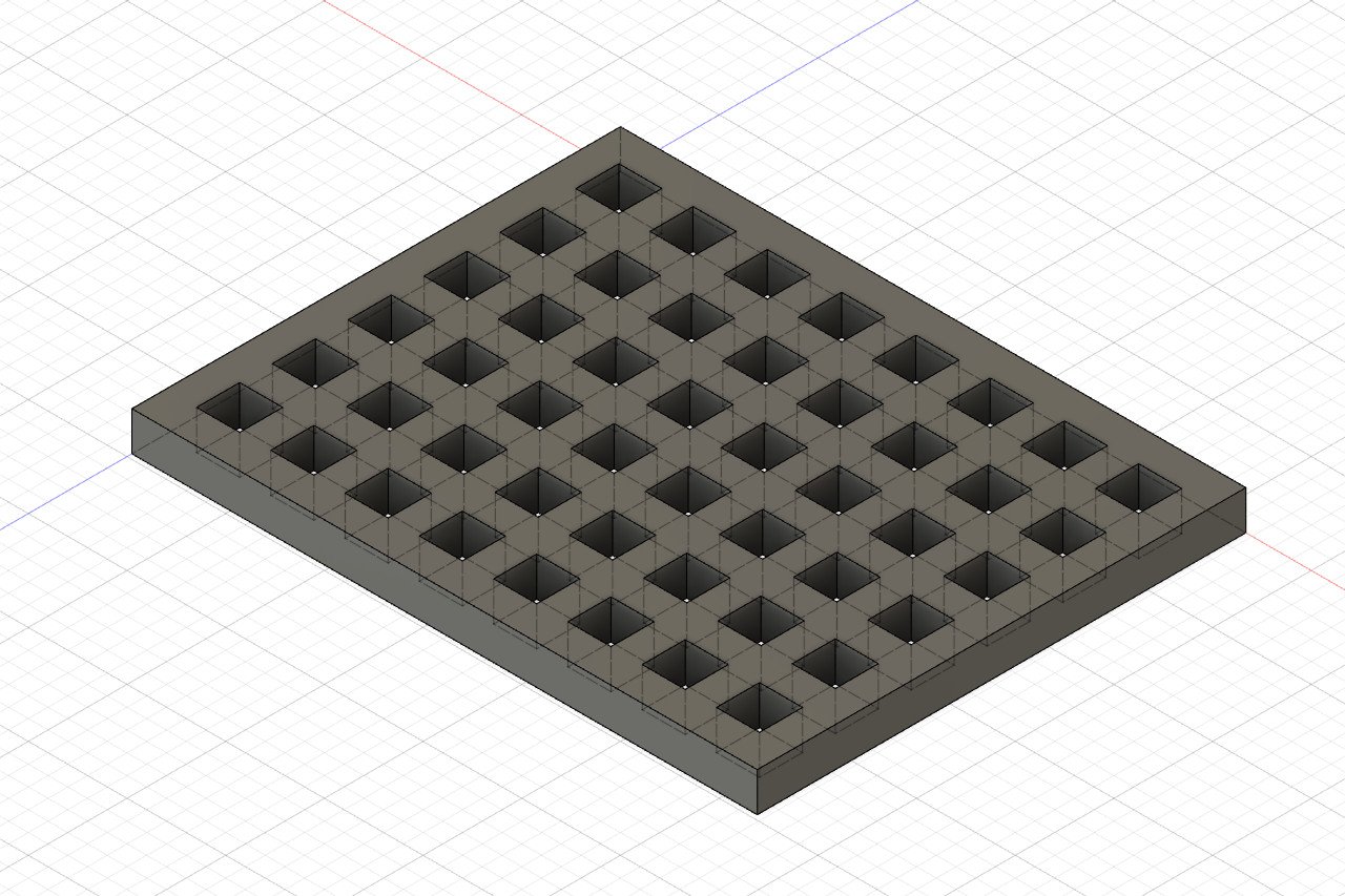
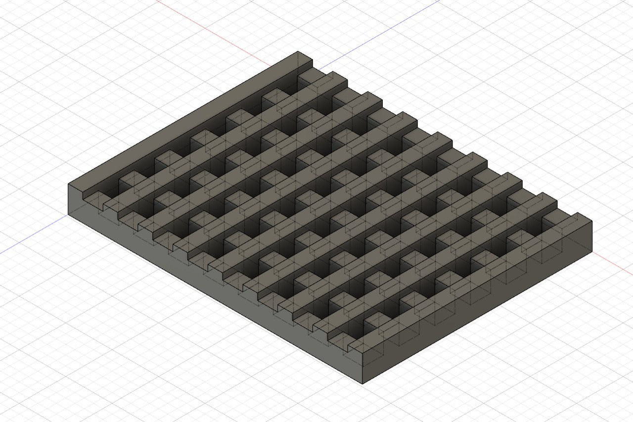
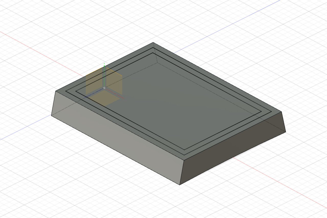
Creating a grating in Fusion 360 isn't too hard. Draw a rectangle, draw one of the square holes, use a rectangular pattern to create the remaining holes, then extrude the sketch.
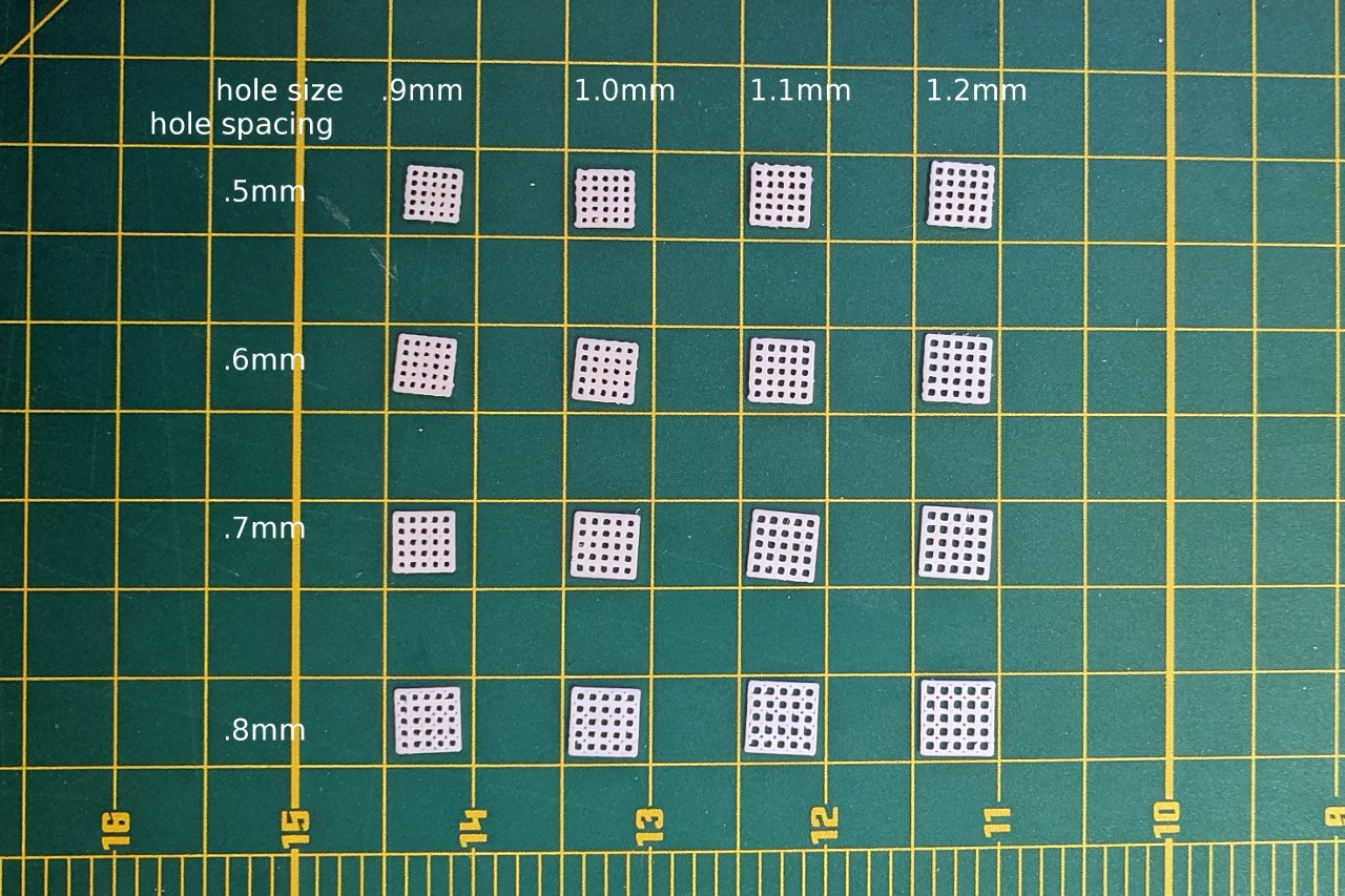
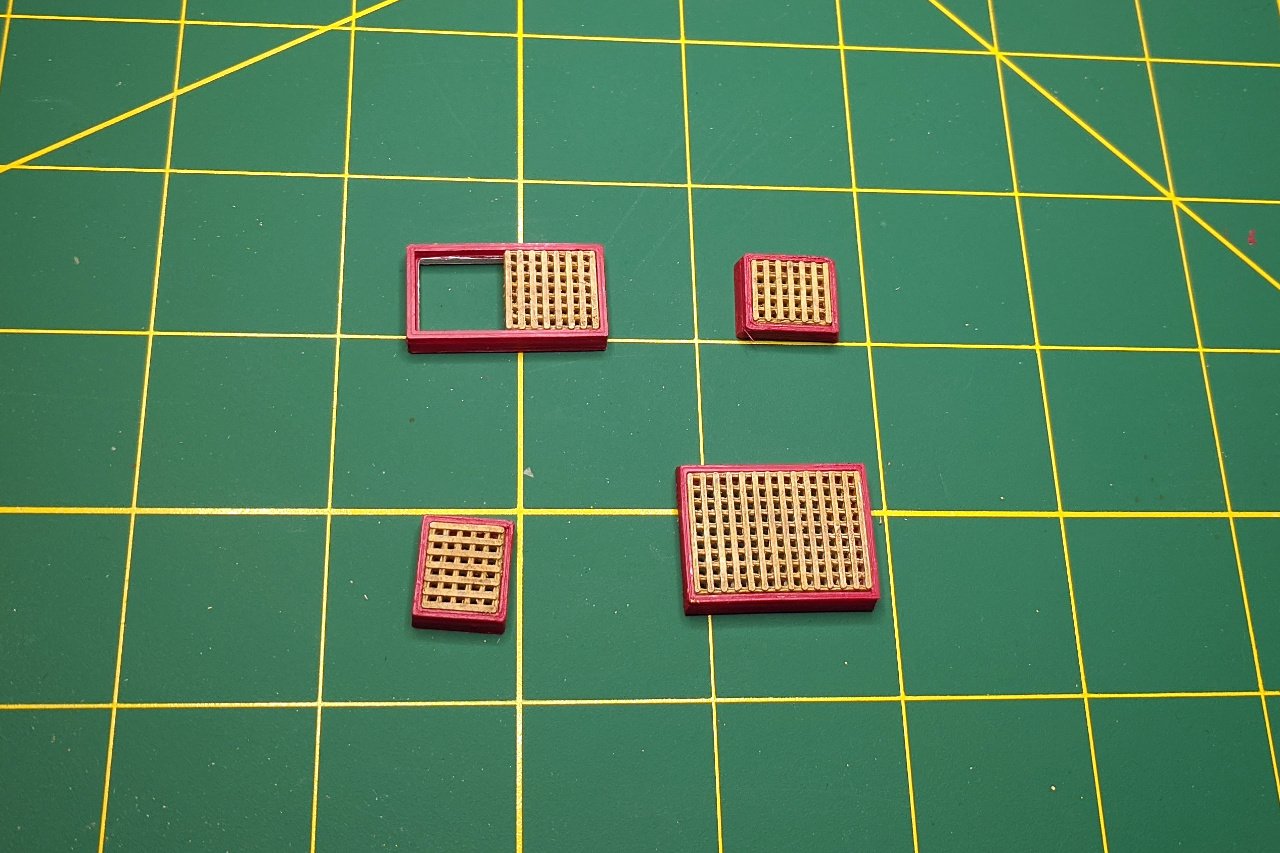
For the grating on the Sultana, I need to have the holes and space between holes at roughly .6mm in size. I ran an experiment to see how small I could make grating that still retained square-shaped holes. As you can see, the pieces in the lower right are acceptable, while the ones in the upper right are not. This shows the limits of what I can do with 3D printed grating.
After some experimenting, I found that having the surface raised in one direction makes the grating look better.
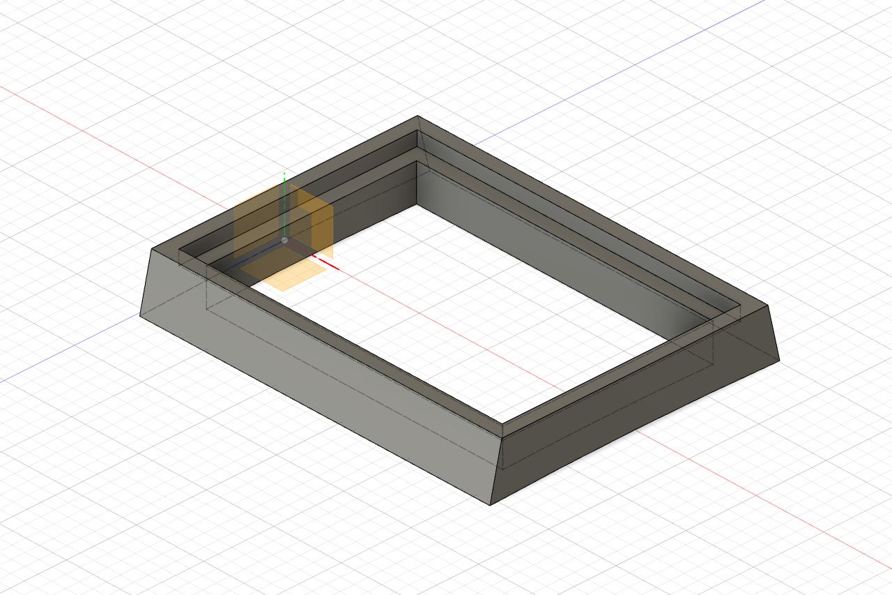
Next is the hatch coaming. From my earlier work, I already knew the exact curvature of the deck camber.
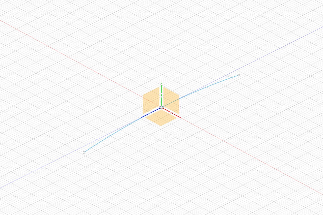
From there, I created the profile of the coaming.
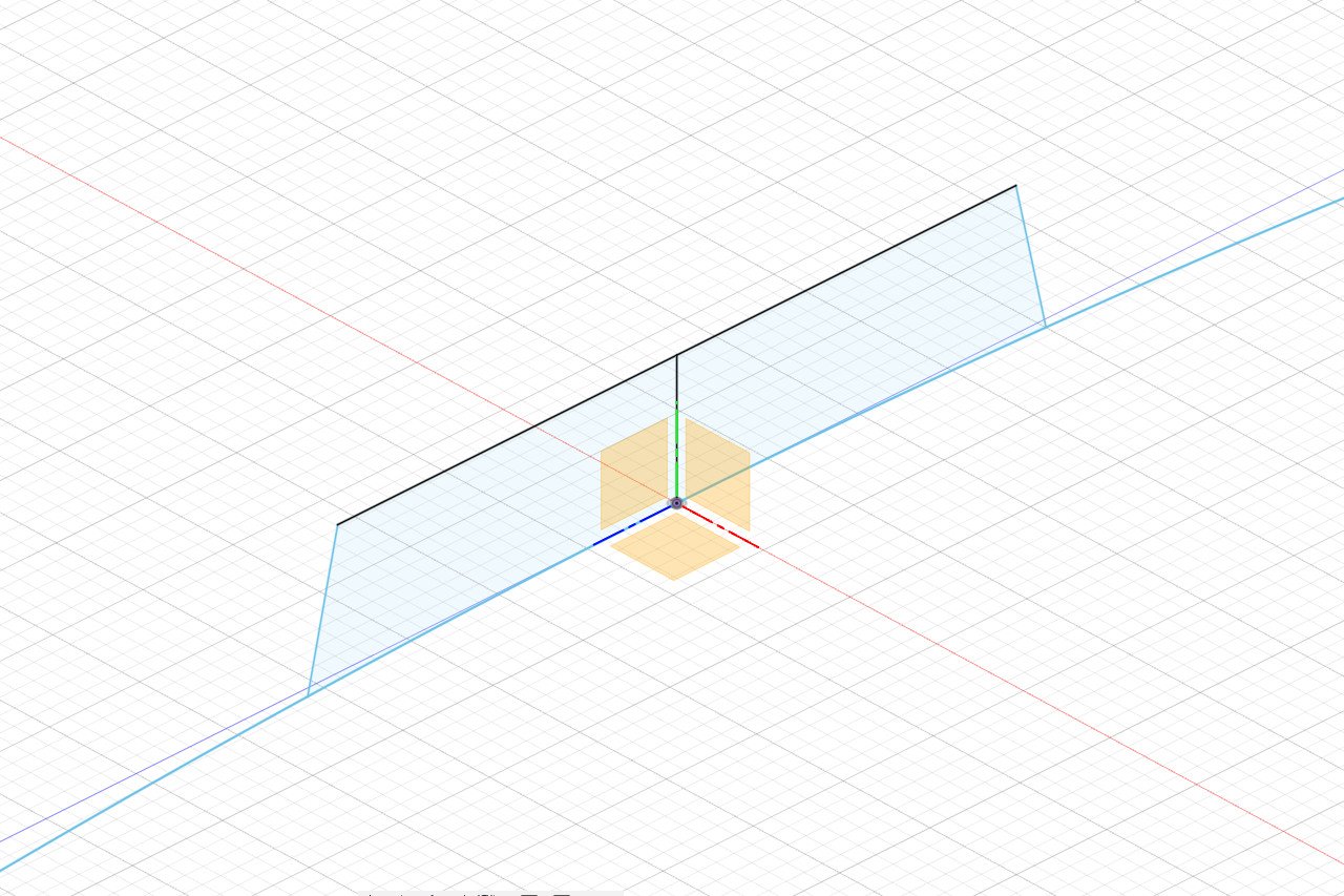
And then the profile was extruded.
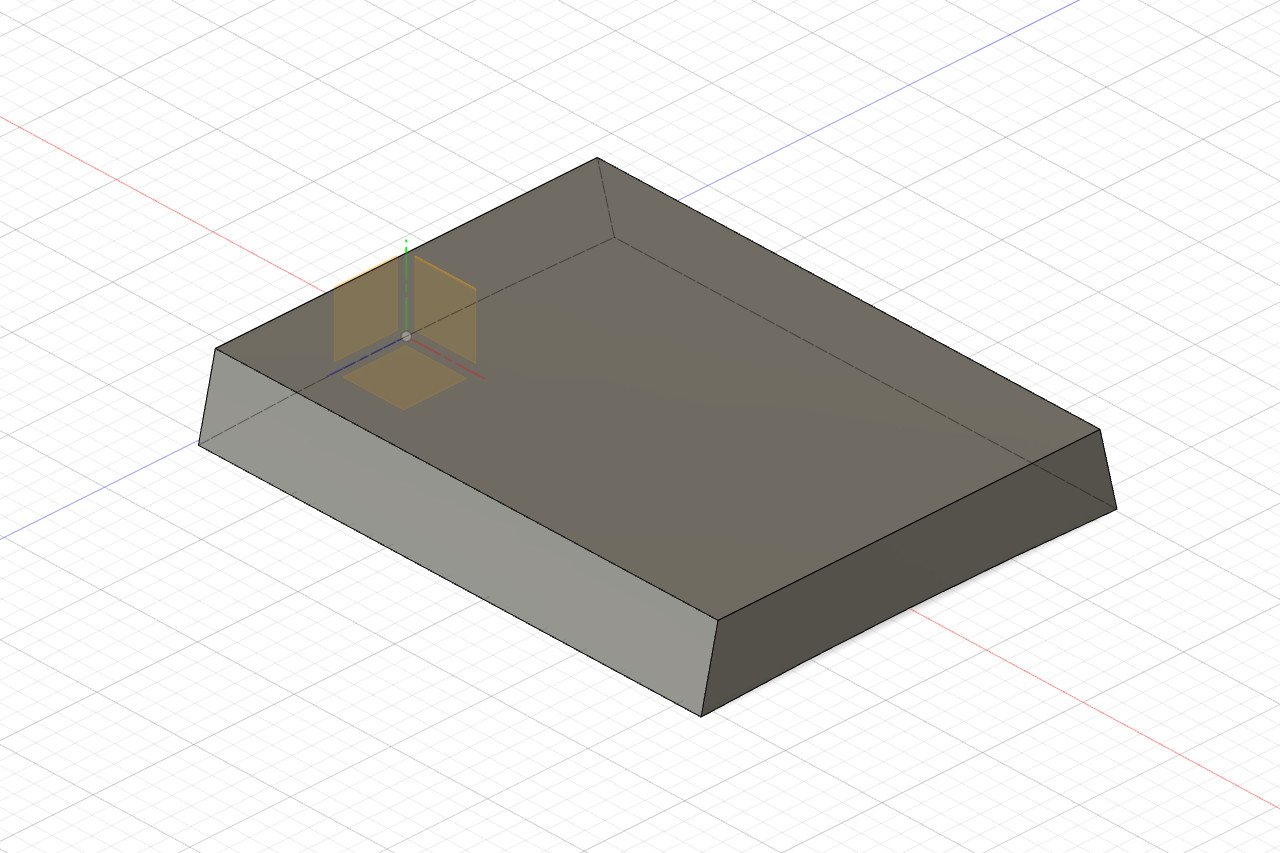
I created a new sketch on the coaming surface to indicate where the recess is.
And the relevant parts were cut out.
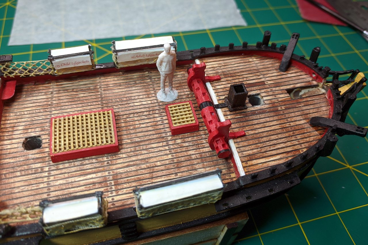
After 3D printing and painting, here are my final hatches.
And here are the hatches on the model. The aft-most small hatch hasn't been glued down yet, because I need to place the binnacle first, then glue the hatch an appropriate distance from the binnacle.

- yvesvidal, GrandpaPhil and hexnut
-
3
-
-
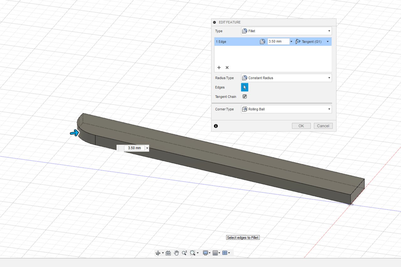
This details building the ladder. First, one side of the ladder is created. The fillet feature allows the ladder to be rounded off at the top.
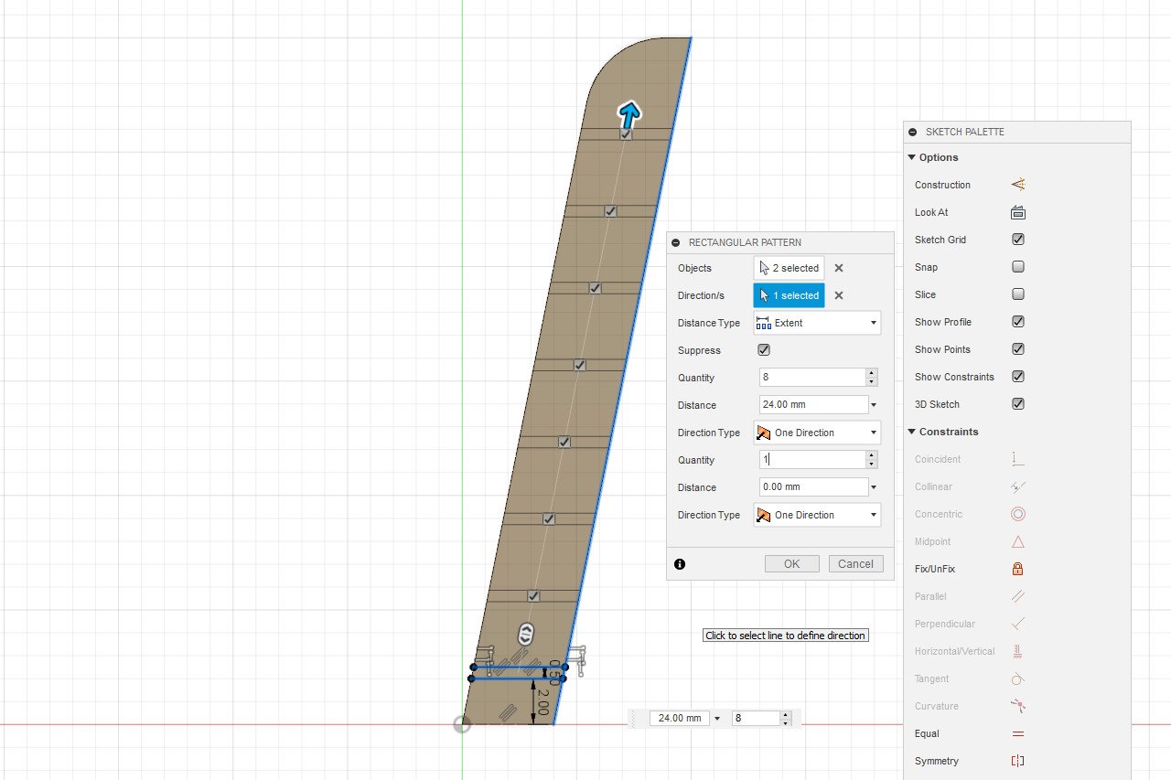
One step of the ladder is created, and a rectangular pattern operation creates the remaining steps.
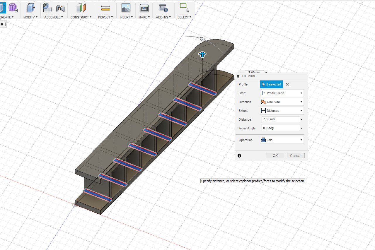
Extrude the steps and add a copy of the side piece, and the ladder is complete.
Using a knife, I scribed some lines into the 3D printed part to simulate wood grain. The piece was painted a wood color followed by a brown wash to enhance the texture.
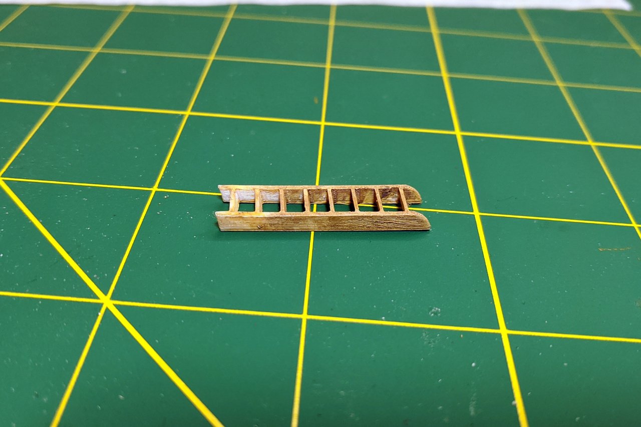
And finally, the ladder is glued into place.
- GrandpaPhil, lmagna, hexnut and 1 other
-
4
-
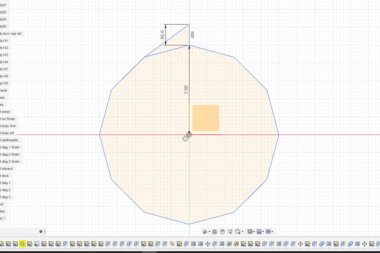
Let's build the windlass, starting with the ratchet gear. After studying a number of pictures of the Sultana's windlass, I determined that the ratchet gear has 12 teeth. I created a 12 sided polygon and added one tooth.
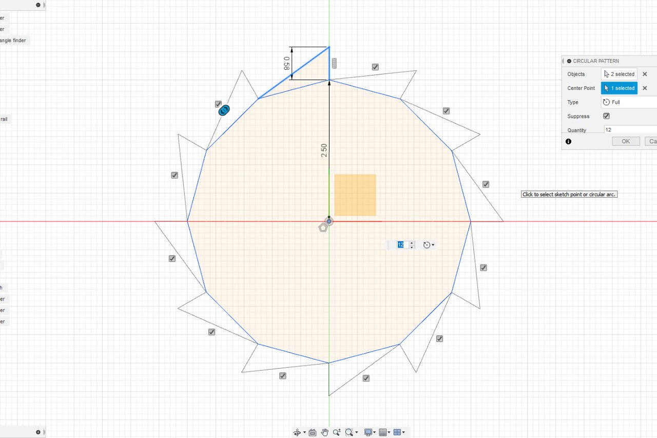
Then I used the circular pattern function to copy the tooth for a total of 12 units.
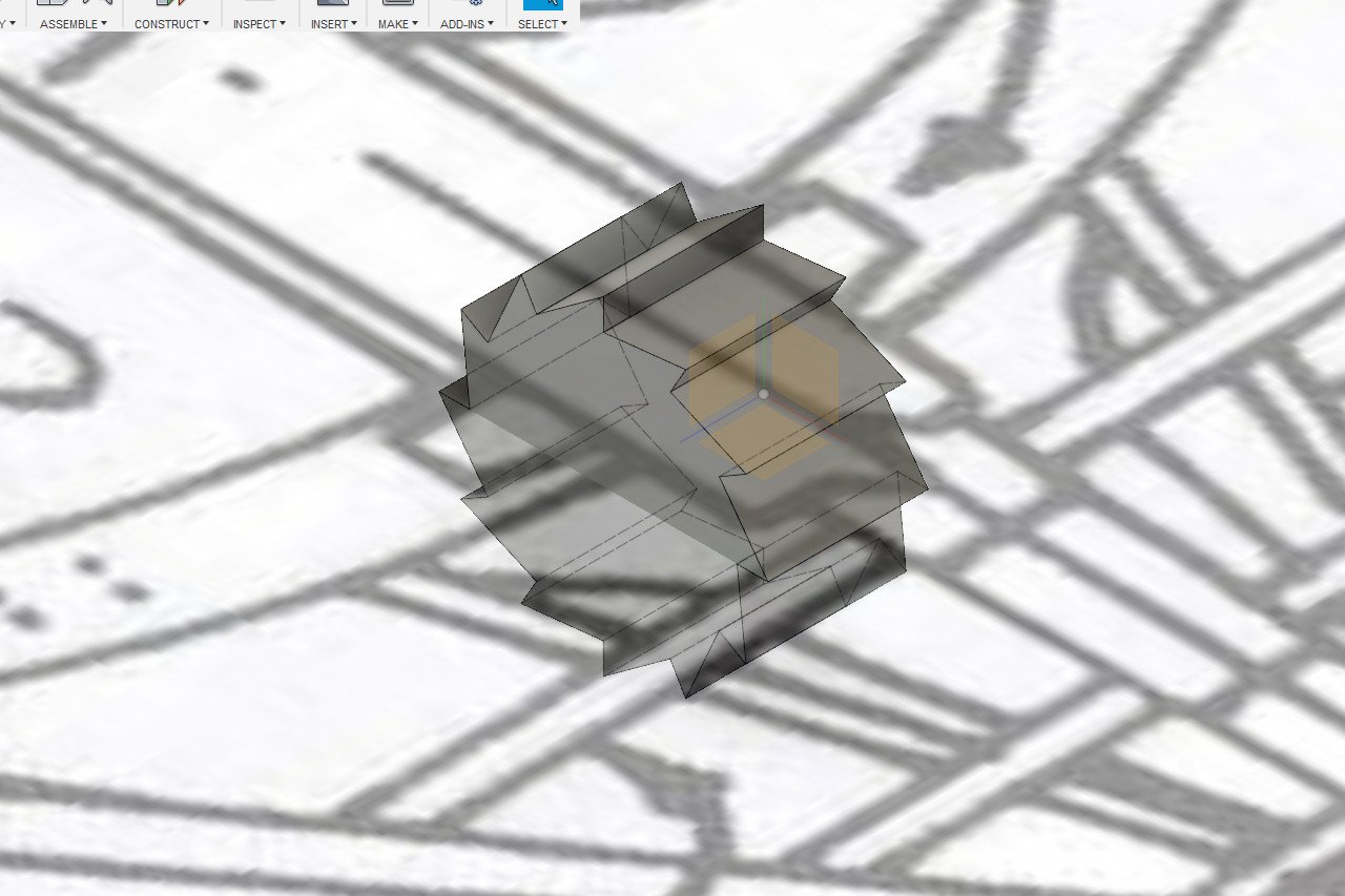
An extrude operation created the final shape of the ratchet gear.
Adjacent to the ratchet gear, I created an octagon, then a second smaller octagon the correct distance away.
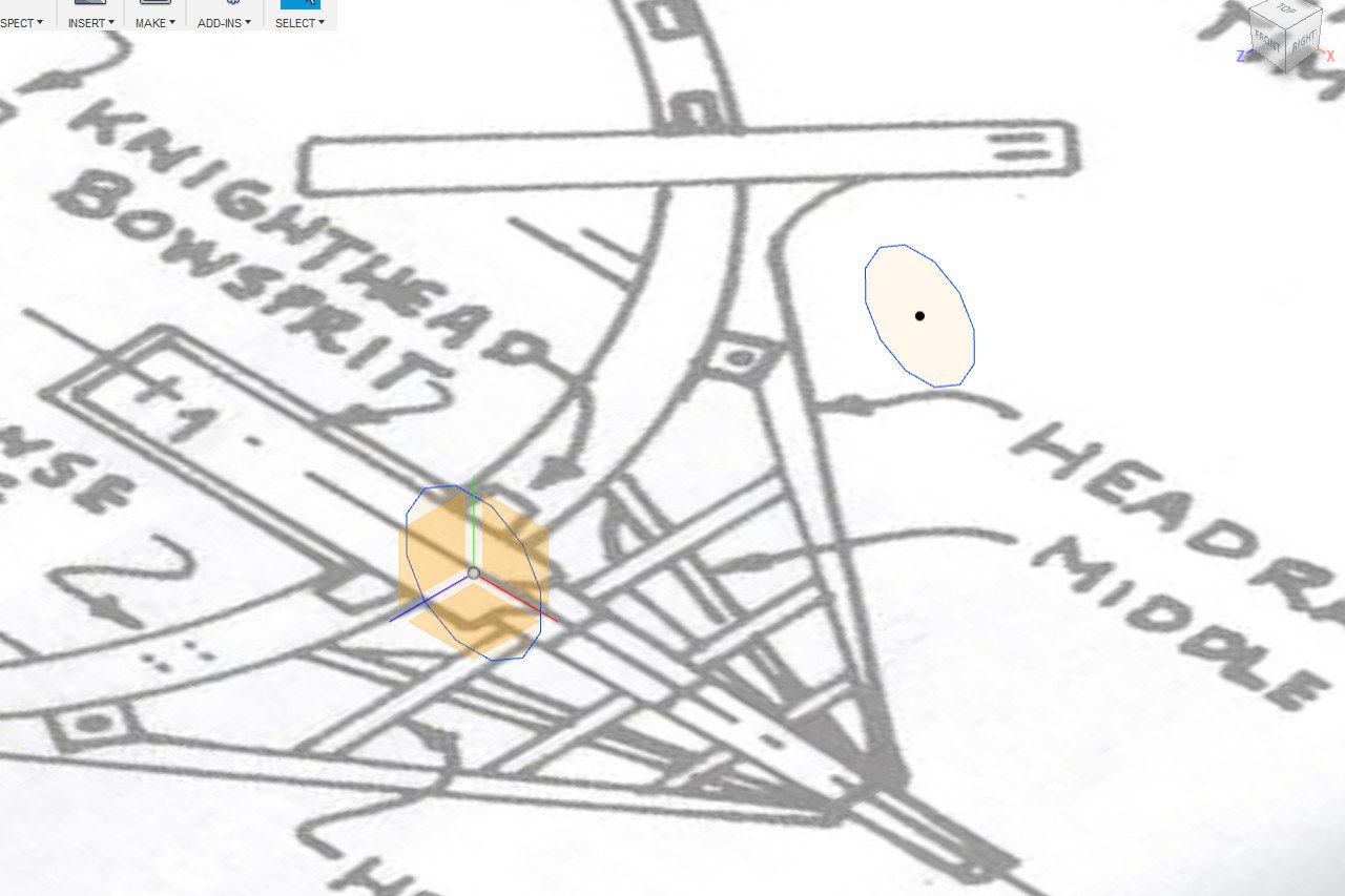
I used the loft function to create a shape between the two octagons, then mirrored that shape to the other side.
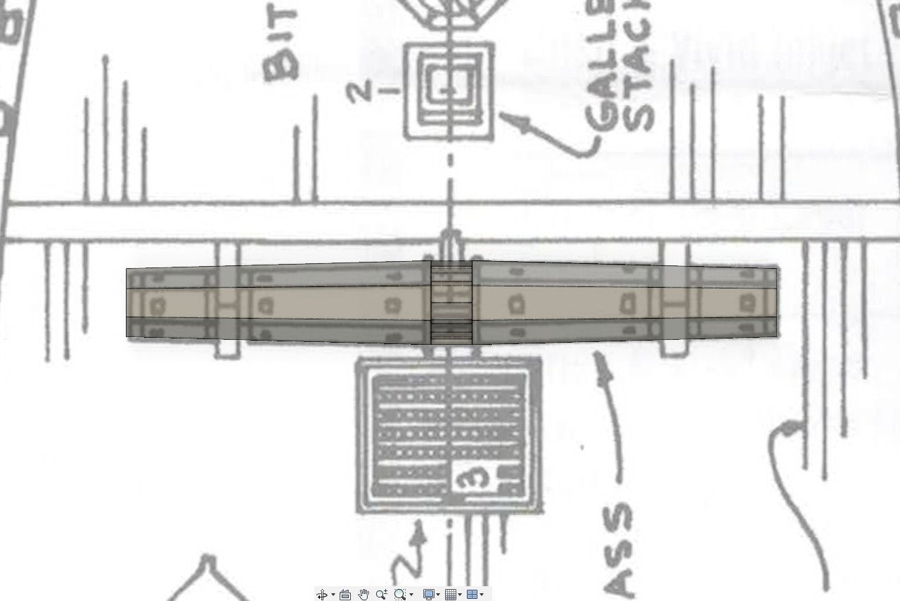
The holes were added and both rectangular and circular patterns were used to place the holes around the windlass.
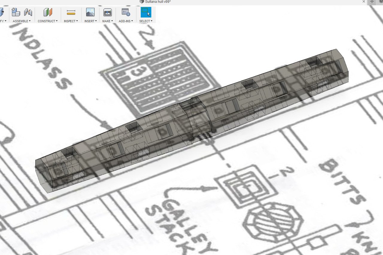
And finally, the supports were modeled.
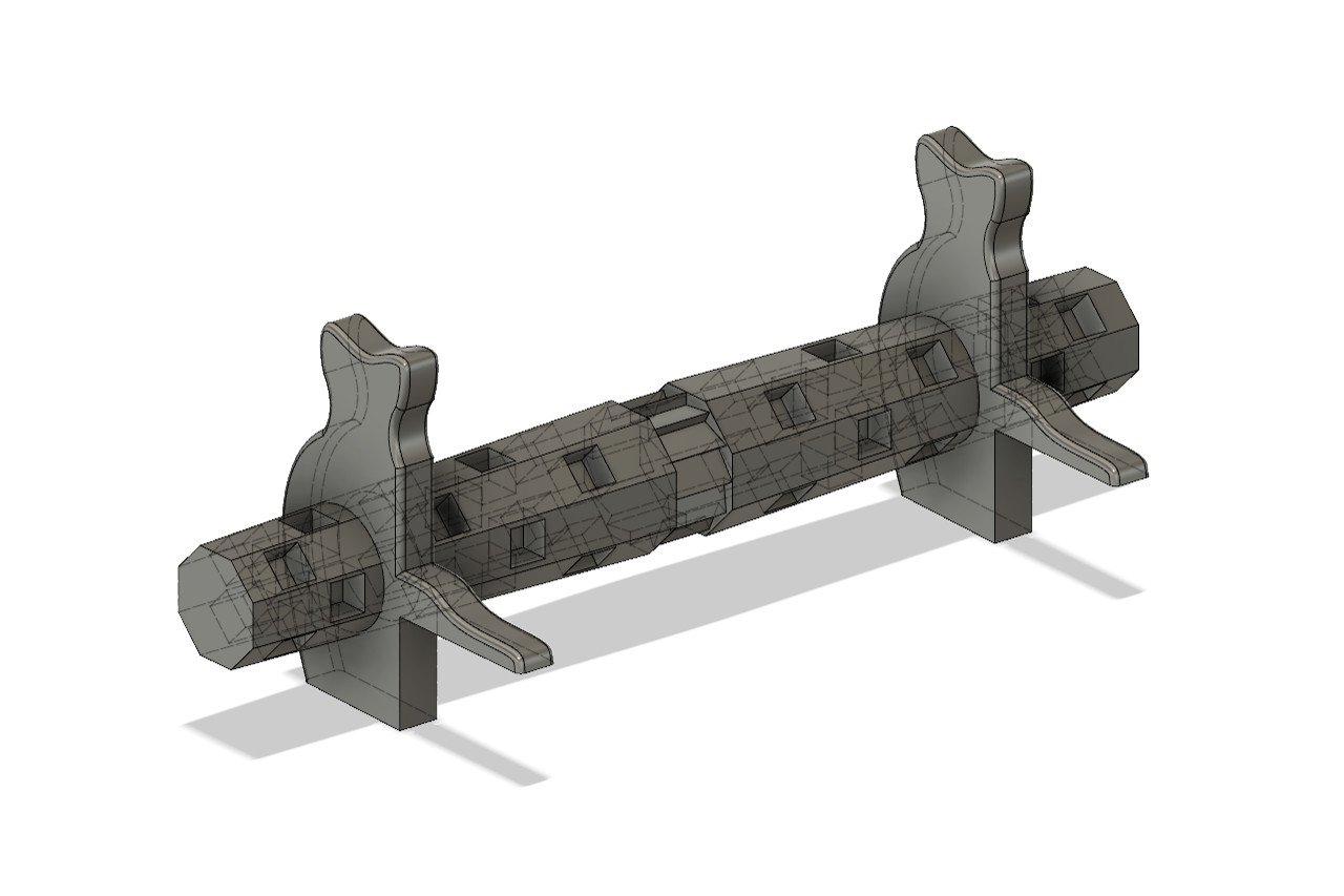
All of the windlass parts were 3D printed.
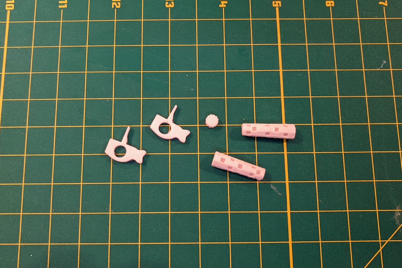
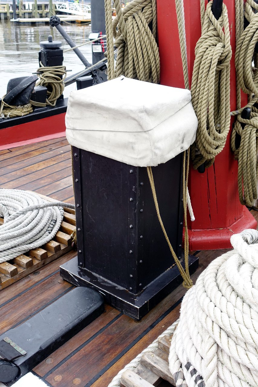
The windlass pawl and galley stack are connected. Here is a picture of the galley stack. For now, I have decided to omit the white cover on the galley stack.

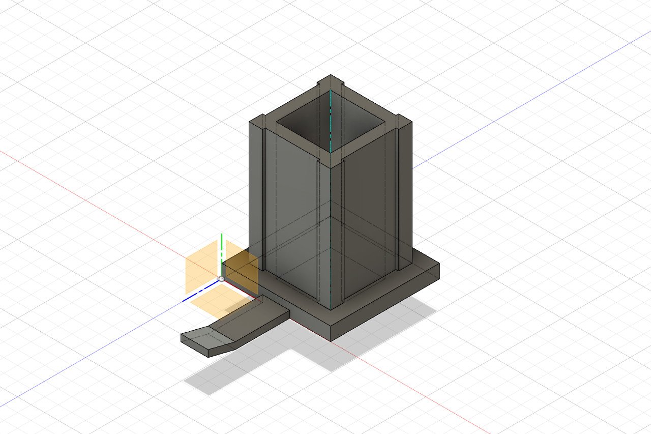
This is the galley stack 3D model.
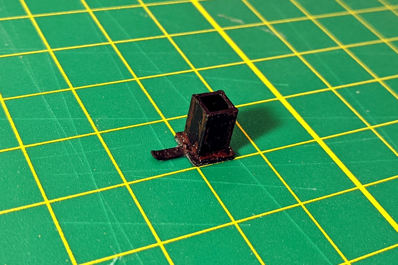
And this is the 3D printed part. I used some burnt sienna paint to indicate rusting. (There is no rust in my photo of the galley stack, but it is present on other photos I have found.)
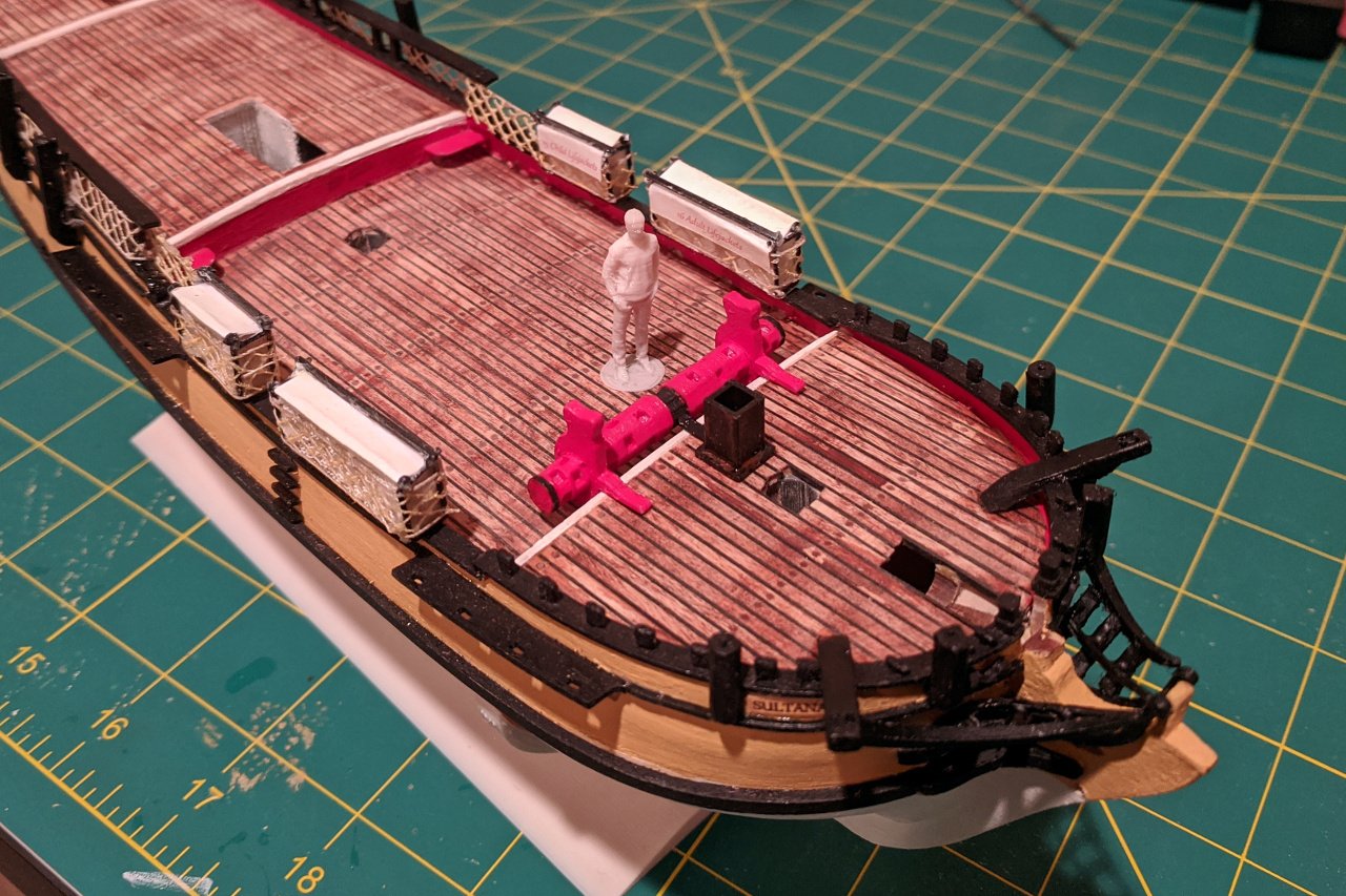
The windlass and galley stack glued on to my Sultana.
- GrandpaPhil, hexnut, yvesvidal and 1 other
-
4


HMS Bellerophon 1786 by AON – scale 1:64 – 74-gun 3rd Rate Man of War - Arrogant-Class
in - Build logs for subjects built 1751 - 1800
Posted
If you're having printing trouble, you might consider breaking the design into multiple pieces and gluing the parts together afterwards.