
MORE HANDBOOKS ARE ON THEIR WAY! We will let you know when they get here.
×


hamilton
-
Posts
1,930 -
Joined
-
Last visited
Content Type
Profiles
Forums
Gallery
Events
Everything posted by hamilton
-
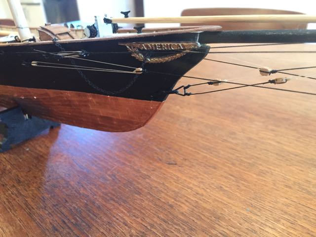
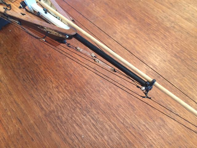
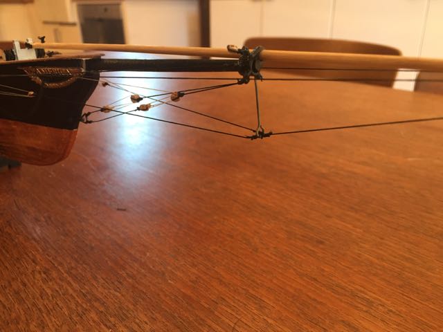
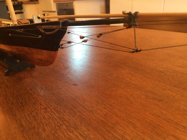
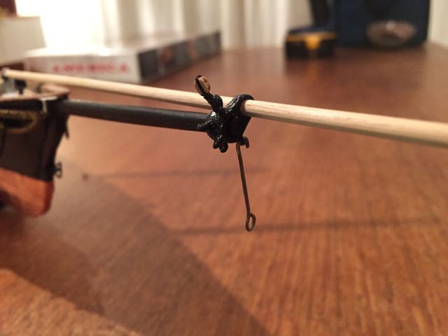
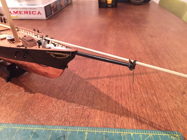
 The bowsprit rigging was quite straightforward - though getting the dolphin striker to stay in a 90 degree position from the bowsprit was tricky. Here are some photos -- until next time! hamilton
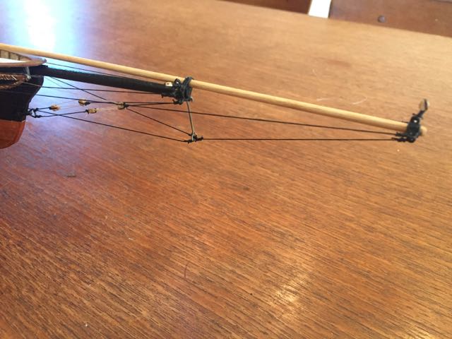
- 165 replies
-
- 10
-

-
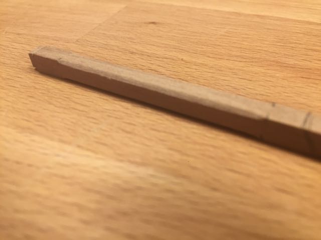
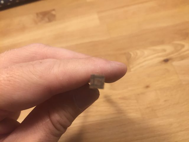
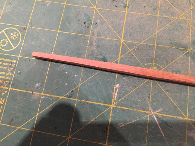
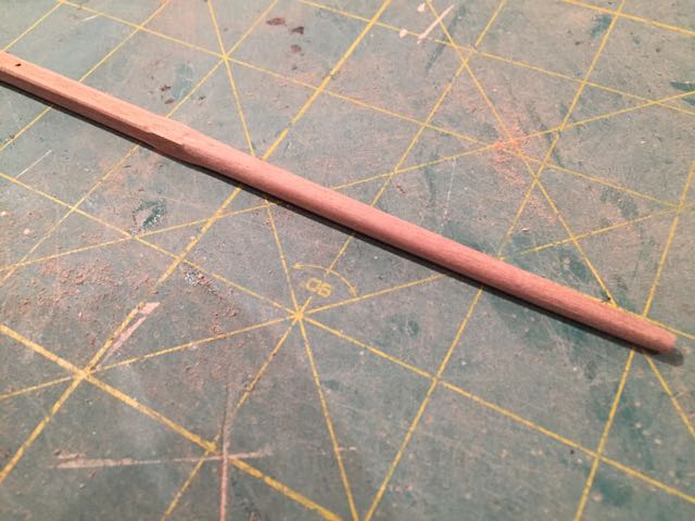
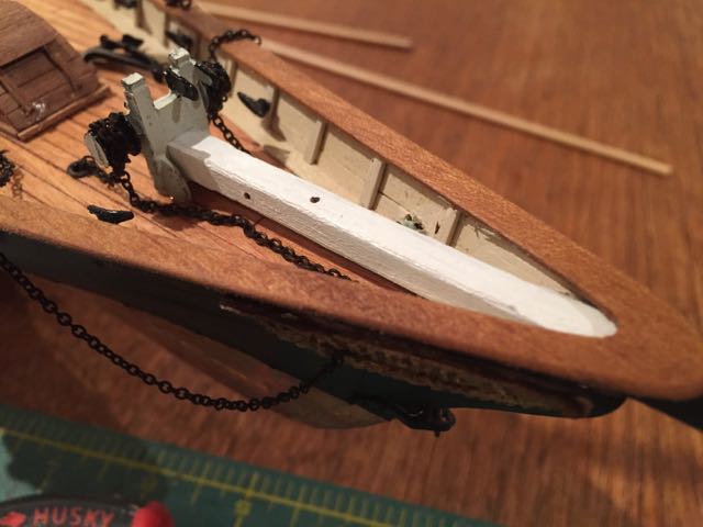
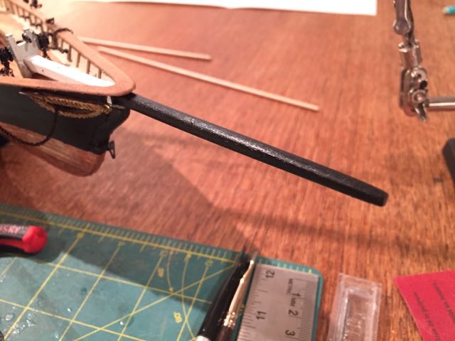
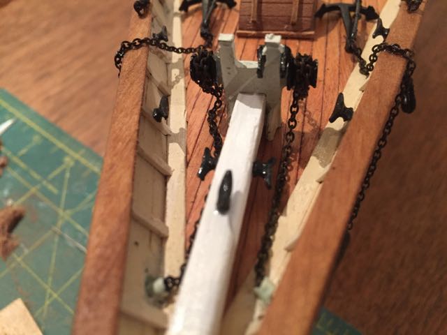
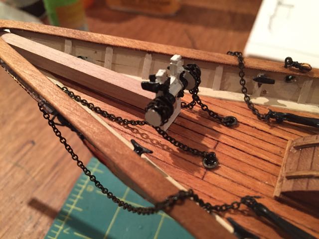
OK - time for another update. I've completed the bowsprit and jibboom as well as the standing rigging on both. I'll split this update into two posts....first, the bowsprit. The bowsprit is made from a 5mm x 5mm strip of square stock. The first step was to mark off the transition between the inboard (square/white) and outboard (rounded/black) sections. I decided to add a bit of chamfering to the inboard square section, as you'll see here. A tenon was created on the inboard end to fit into the bitts.... The bowsprit tapers to 3mm at the outboard end, so using my compass set to 1mm, I marked out the outboard end - the idea being to taper each of the square faces and then round the tapered strip. Here are the results I then drilled out holes for the inboard cleats and threw a few coats of while and black paint on..... Two irons are fit at the end of the bowsprit - one a simple iron ring that takes the standing ends of some of the rigging and the other a gammoning iron for the jibboom which also carries some lines. These fit on relatively well and their completion was not particularly exciting....you'll notice the martingale attached here - it did consist of two rings, but one of them snapped off and I had to improvise a bit.....the jibboom is here just a dowel cut to length.... Continued in next post...... hamilton
-
Haha! That's an argument for keeping them where they are, I suppose......despite the oddity.... hamilton
-
Hi Per: I'm not sure if you're offering to pick this up for me? If so, thank you, but I have to decline! I don't really have any room for it, though it would be a nice addition to the collection..... Tim - thanks for dropping by! Yes, this one is currently still in development - I was hoping to commence this month, but it doesn't look like I will....America will have to be finished first.....and even then, I'm heading into another academic year and my modelling progress will slow altogether....I plan on teasing out the Bluenose in tandem with other kit builds.....Syren is next up on the docket, though I may take September to focus more on Bluenose and dive into Syren later in the Fall.....much depends on feeling out what kind of year it's going to be - the last two have been really nutty, and though I'm hoping this one's calm, it's already shaping up to be very busy........ bye for now hamilton
-
Thanks for the tips Peter - Dremel doesn't seem to make their scroll saw any longer - they just have a hand held "moto saw", which has a clamp so it can work as a stationary table-top device. I haven't seen any dremel scroll saws on sale at any of the usual online places.....I'm going to try to source some thin band saw blades, but so far have been absorbed in finishing my Mamoli America and, of course, other commitments! I hope to get the keel and bulkheads cut before it gets too rainy up here........thanks again for the comments! hamilton
-
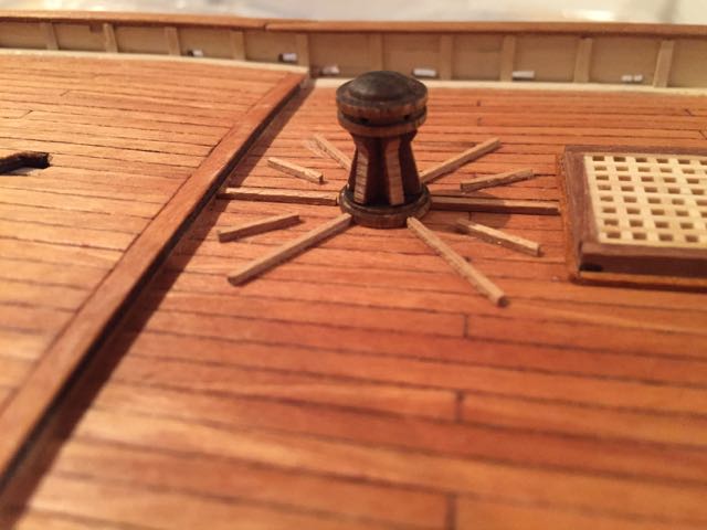
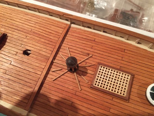
Hi Peter: Yes - I'll admit that this feature seemed pretty strange to me, since obviously under sail they'd be flying all over the place....unless of course they are footholds - which would make some sense - except why would they be different lengths.....the kit parts list clearly states that they're "capstan bars".... Anyways - It may be too later to pull them up and doing so might really mess up the decking....I will leave them for now - thanks for the comment! hamilton
-
Looks nice out there! Hope you're having fun hamilton
-
Thanks Ferit, Tim and Bob! Ferit -- the hamilton ship yard will soon be taking a break and then coming back in a much slower and less regular way.....I had a long-ish vacation this year and the "summer" out here has been dramatically delayed (cool temperatures and rain.....through most of July)......it's nice to spend some time at the bench though! Still looking for updates on your amazing Berlin! Tim - yes I think you're right - but I wondered why the Mamoli drawings only show four of those bars when it seems there should be six -- two more at port and starboard where (you'll see above) they're missing.....I've seen other modellers position the capstan bars in a fan on deck like this, while others represent them lashed up somewhere or not at all. Seems open to some interpretation, at least in the absence of any concrete knowledge! Bob - thanks very much! bye for now hamilton
-
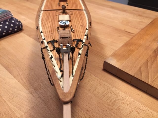
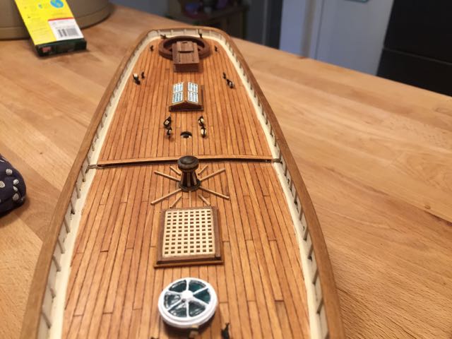
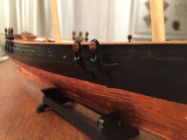
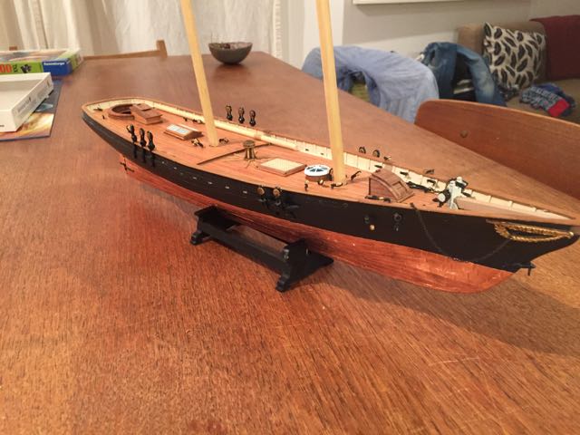
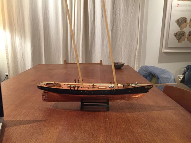
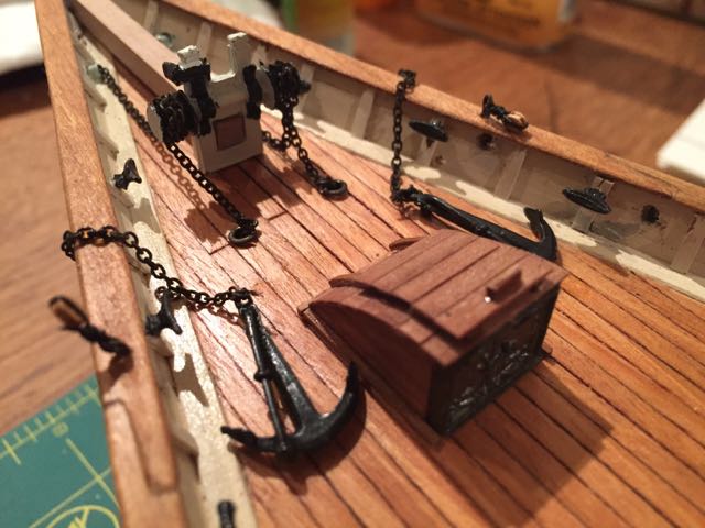
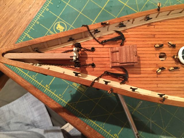
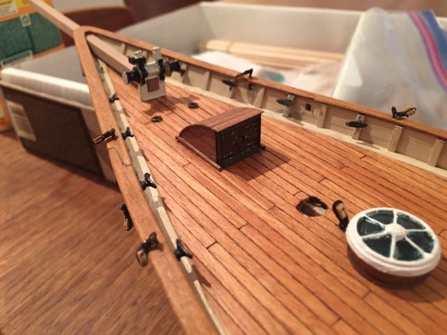
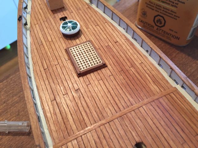
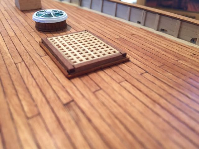
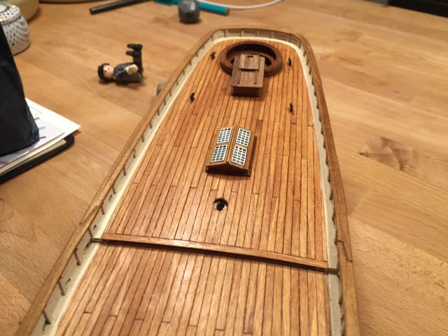
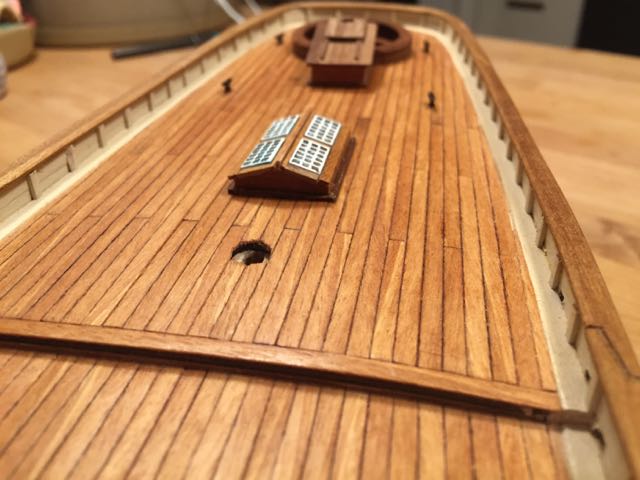
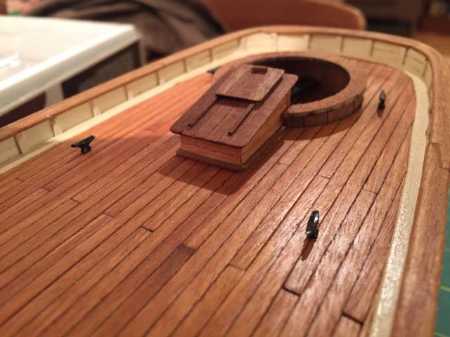
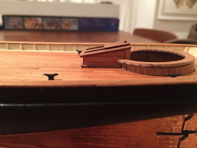
Here are a few overview shots of the finished deck features. And finally some shots with the deadeyes, fore channels and chainplates - last of the main hull/deck features. hamilton
-
I then fit the anchors and anchor chain. Not much to tell other than that it took some finangling to get the chain through the hawse ports......
-
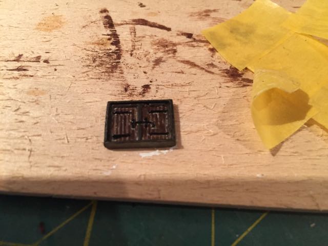
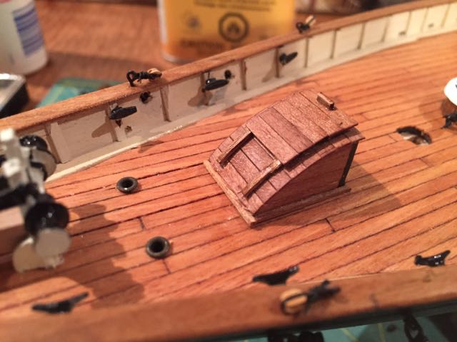
The forward companionway was also relatively straightforward. I considered briefly scratch building the doors, but I did not have any wood stock small enough for the purpose and lack the skill and equipment to cut my own.....so I just went with a paint job on the part supplied by Mamoli. Black for the hinges and handle, raw umber for the framing and burnt umber for the panelling. Not the best paint job in the world, but.....
-
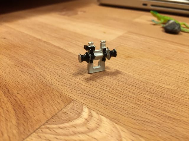
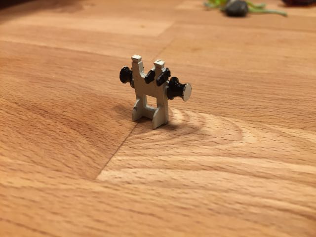
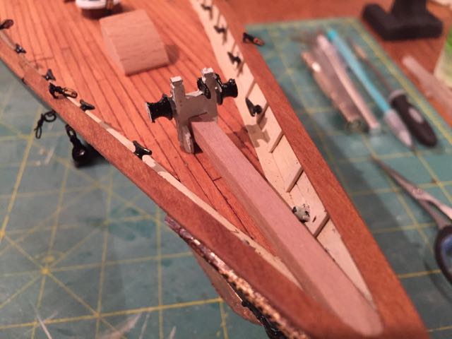
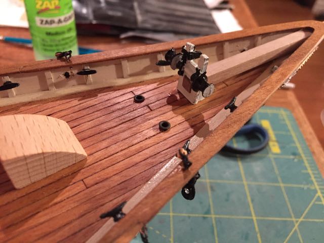
Here are a few shots of the windlass and bowsprit bits. I made a point of rough cutting and cutting a tenon into the bowsprit at the same time. hamilton
-
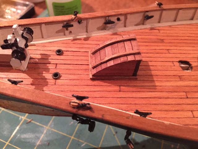
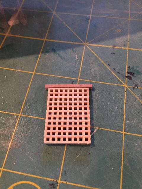
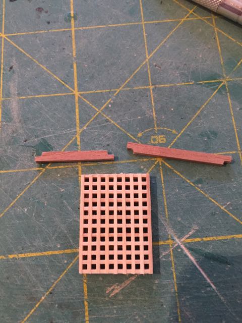
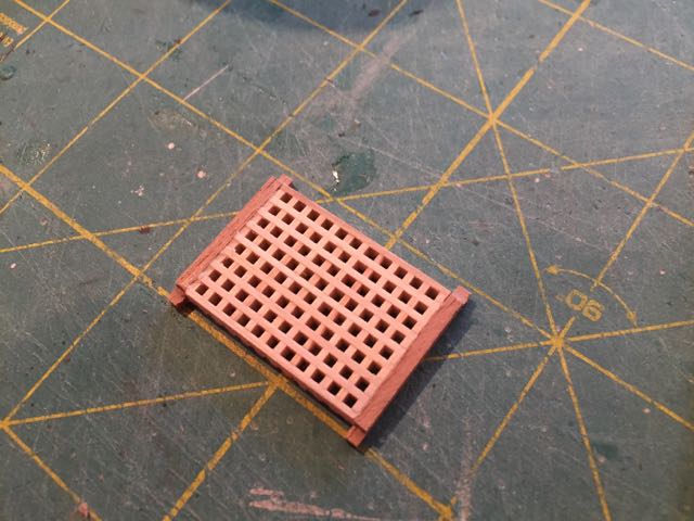
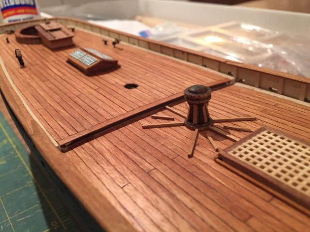
Hello all: More progress on America - quite a bit actually: I've finished the hull and deck features and will now move on to the masts, spars and rigging. A real milestone. Since there's quite a bit to document, I'll separate this update into a few posts.... First the main hatch. I decided to make lap joints for the coaming - I cut the fore and aft parts so they overhung the gratings by 1mm on each side, marking and then cutting out a small 1 x 1.5mm (roughly) section. The parts fit together alright..... Next up was the capstan, which was very straightforward -- thanks go again to Tim (mojofilter) for supplying some whelps -- Mamoli only put 2 in my kit.... hamilton
-
unfortunate circumstance with the Cheerful Bob! Glad it was salvageable! I have a couple of child-damaged models that I have not had the time or patience to do the (fortunately) minor fixes on -- I can't imagine the kind of damage that would have required 40 hours of repairs....... The Granado is looking very fine, though! A lovely model and one I would love to build one day (my signature explains why I will not be purchasing any more ship kits in the near- to mid-future...... hamilton
-
Hi Tim -- I think my cockpit is too small, given your research.....but I'm not in a position to re-do it now!! I should probably have remade the cap at least when I remade the seat piece - this would probably have resulted in a slightly wider cockpit, even if it wouldn't have been exactly to the dimensions you quote.... I did take a look at your research and it was very interesting....Are you considering omitting the main gaff topsail? I think I will include mine as I like the look of it and I'm pursuing this build more for aesthetics and refining my modelling techniques than for historical accuracy (I'll save that for my Bellona when I finally get to it!) Your timing in offering the chainplates is immaculate! I fit them last night and I ended up crushing one of the deadeye strops....However, I scratched one out of an old leftover soft metal gudgeon from another kit.....I positioned this one on the port (non-display) side for the foremast shrouds where it won't be too visible. I guess I didn't account for how soft and fragile the metal parts are! Anyway, I'll post a few more photos later tonight - bye for now hamilton
-
Sounds like a really great reference Tim - thanks for posting these details - would love to see some pics of your progress too! hamilton
-
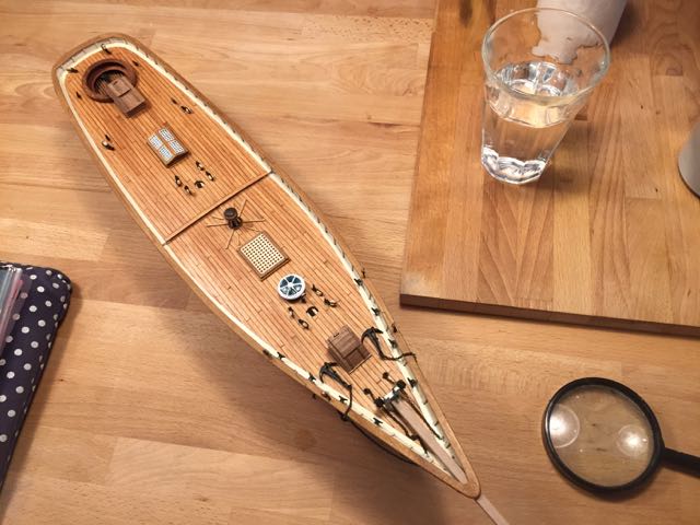
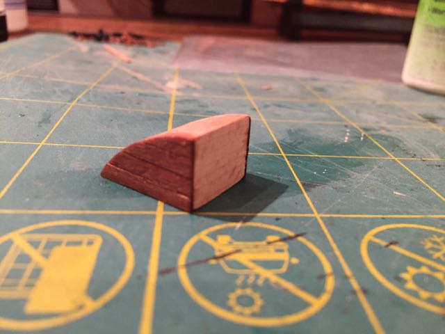
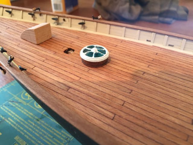
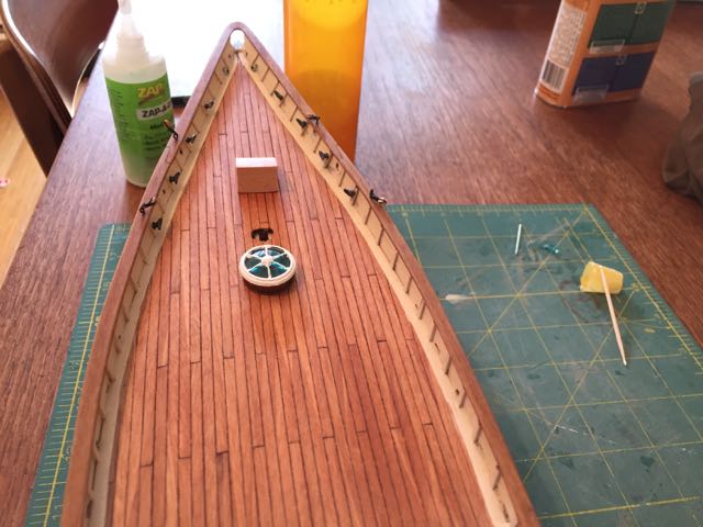
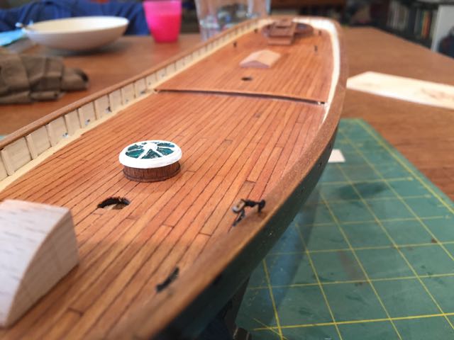
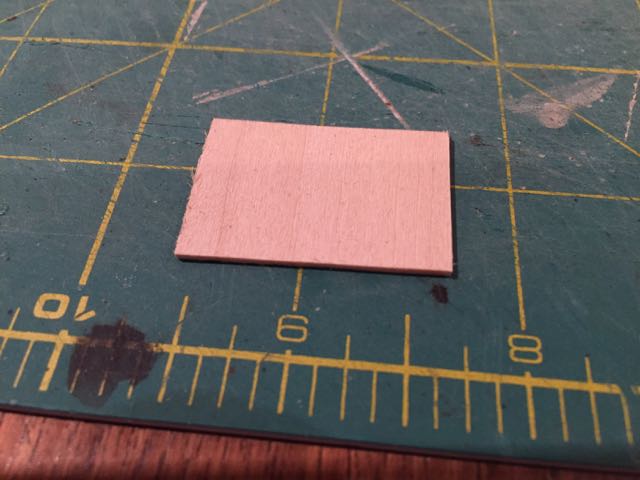
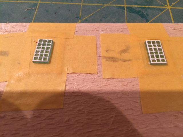
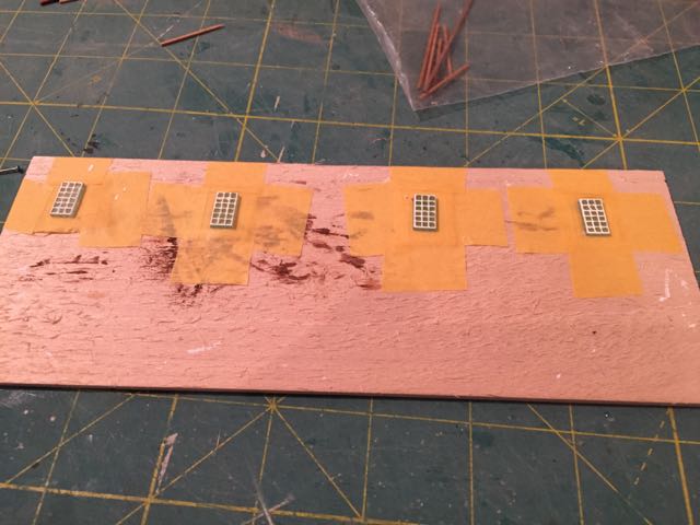
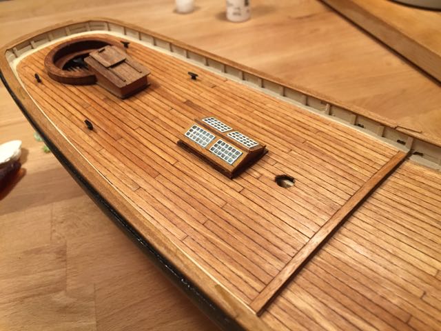
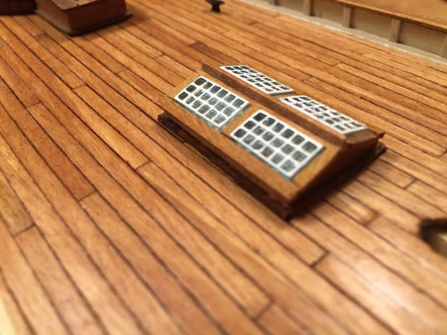
Another small update - this one dedicated (if I may) to fellow America builder Tim (mojofilter), without whose generosity I could not have proceeded with this part of the build - he sent me some extra parts from his kit that I was missing from mine - including one of the aft skylight windows. Today I constructed the forward and aft skylight and thought thankfully of Tim's kindness. The forward skylight was pretty straightforward though I'm not sure I've done the best job on the finish - I used a small paint brush, but probably wanted a smaller implement like a toothpick or (what I used for the aft skylight windows) a straight pin.....anyway, it was just a question of painting the plastic part and fixing it atop the base, which also came pre-figured....here is it....a bit messy.... The aft skylight was not exactly tricky but took a lot of work. The basic part comes as a pre-cut wooden framework. I sanded the very top of it flat and placed a vertical 1mm x 2mm walnut strip atop the levelled section as a kind of centre board. On either side of this I placed 1mm x 1mm strips as lintels for the skylight windows. Here's a photo As you can see, the piece is very low, but the plans call for a 1mm x 1mm coaming around the bottom. This would have effectively hidden the sides of the skylight altogether and (to my mind) resulted in a pretty inaccurate shape. As a solution, I decided to fix the piece on top of a piece of 1/32 basswood sheet cut so that it overhangs the skylight by about 1mm on all sides. I don't have a good shot of this, but to make this part look like walnut (and not having any walnut stain), I stained this part golden oak and then put a very thin coat of burnt umber over that - the wood grain shows through the paint (thanks to the emphasis given by the stain) but the colour is dark enough to match the walnut coamings on the main companionway.... The windows themselves I finished with white trim using (as mentioned above) a straight pin and a magnifying glass out of a toy spy kit that my son has. The magnification was like having a film lifted off my eyes. The magnifying glass isn't great, but even then it was so much easier to get the detail at least partially right! My initial attempt at a free hand finish were abysmal. To finish the small plastic windows I first taped them onto a roll of masking tape and then taped down the tape roll on some scrap wood. This fixed the part in place very securely. I then simply dipped the pin lightly in the paint and drew it along the raised lines of the window frames....here are the results - again, not perfect, but I'm pleased. After the paint dried, I took a window and used it on the part to get the position of the window sills, for which I used 1mm x 2mm walnut. Once these were in place on both sides, I positioned the windows to get an idea of where the central wooden window frame should be -- I cut very short lengths of 1mm x 2mm walnut for these and then fixed the windows on. More short strips of 1mm x 2mm walnut on either side and it was done. Here are the results. Enjoy! hamilton

-
Just catching up on your log Bob -- the transom and decking look really great -- it's almost impossible for me to tell that the stern decorations aren't carved! hamilton
-
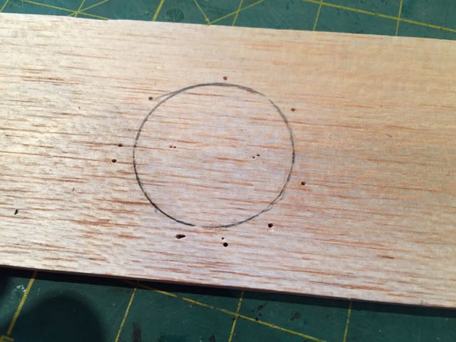
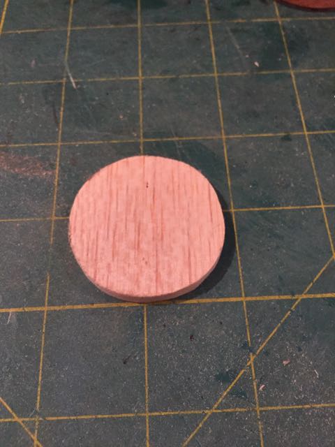
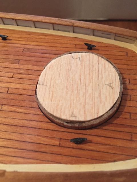
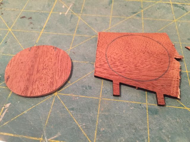
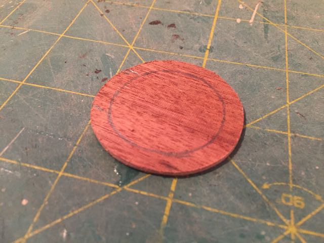
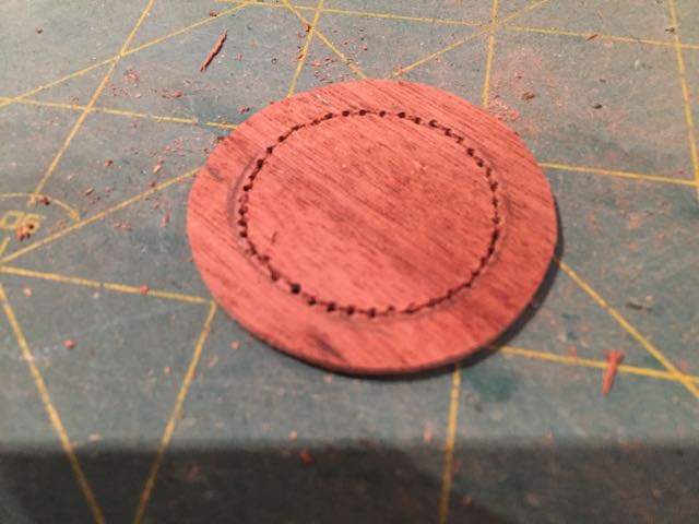
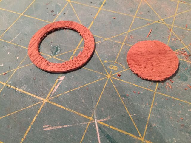
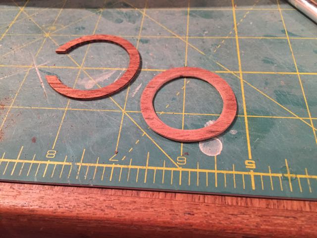
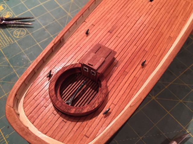
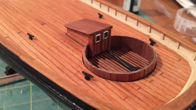
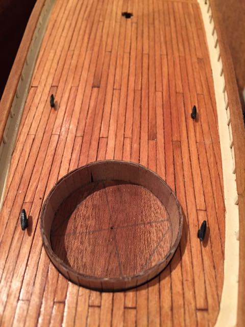
So I needed to make a new part to serve as the cockpit seats. Before I fixed the deck in place, I made a tracing of it on some scrap balsa I had lying around - this represented the dimensions to which I needed to cut the seats to have them fit. After cutting out the balsa template I sanded the edges until it fit in place -- here are a couple of photos I then traced this shape onto the walnut billet on which the original parts came - there was enough room to make two just in case I needed a back up - which in the end I didn't.... Using a compass set to 5mm, I marked the inside edge of the seats. I then drilled holes around the inside circumference, afterwards cutting around these holes with a #11 blade on both sides and cutting out the centre. A bit of trimming and sanding on the inside with the blade and it was looking fine - here are some photos - the last shows the (yet unfinished) seats alongside the cap. After that, it was a pretty simple matter of cutting out a small section of the seat to accommodate the companionway, install it, glue on the cap and then glue the companionway to the deck....here are the final results hamilton
-
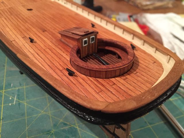
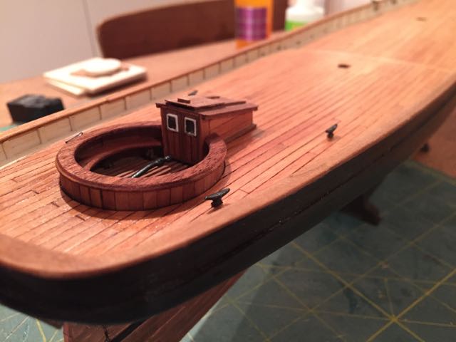
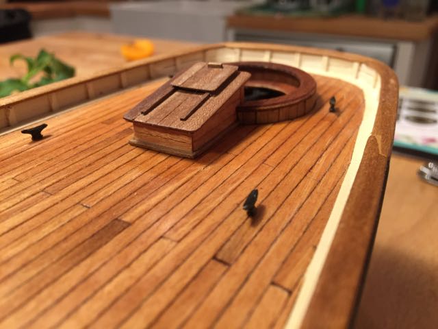
I don't have any photos of the process of making the companionway - it was the matter of an evening and was quite a bit of fun to put together. Here are the results. In some of the photos you can see the cockpit cap - it is not yet fixed. hamilton
-
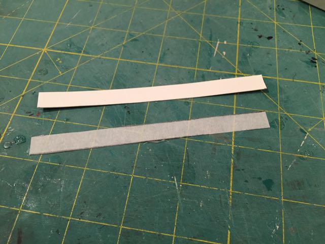
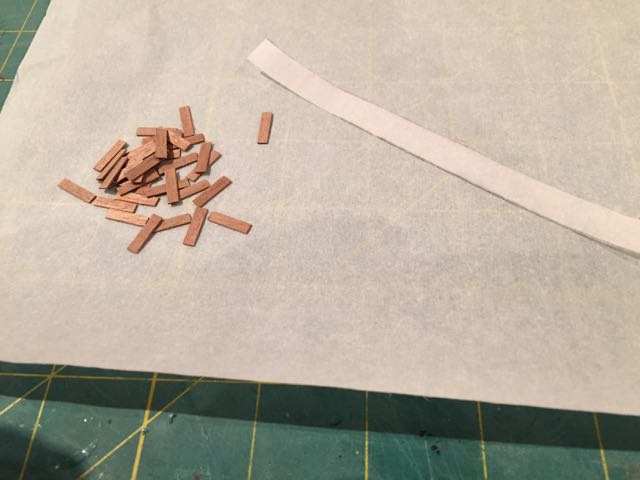
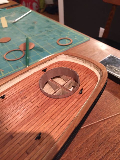
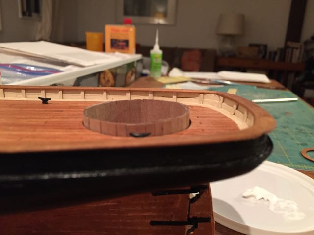
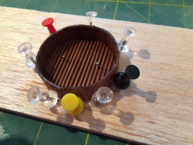
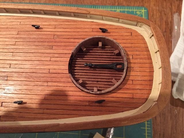
The construction of the cockpit has proved to be one of the more complicated parts of the build - not least because the laser cut parts supplied by Mamoli are not in proportion - they were all too big....the part supplied for the seats I've ended up using as the cap for the cockpit, while the part supplied for the cap is now rolling around the box. If I had had some foresight I could have tested these parts against the hole in the aft deck, discovered the size discrepancy and widened the deck hole so the parts would fit....in the end, I had to make due - as I say, using the kit-supplied seat as the cap and scratching a new seat piece from the ply supplied in the kit.....but I'm getting ahead of myself.... The first step was to figure out the circumference of the cockpit in order to put together the side planking. I cut a random piece of bristol paper, coiled it into the hole, marked where it overlapped and then trimmed it to the total height of the vertical cockpit planks. Using this strip as a template, I cut two pieces of tracing paper to the same dimensions - these will be planked and then glued together to form both the inside and outside walls of the cockpit. The small strips of walnut you see in the last photo were cut using a jig to ensure evenness. Fixing the strips on the tracing paper did not take much effort, though the whole piece needed a trim once it was done to it would fit more or less nicely in the hole in the deck. The laser cut cockpit deck was also a little large, so I needed to find the centre and trim it to fit - you can see both the pencil marks and the compass hole in the first photo below - not much needed to be trimmed - between .5 and 1mm all around. The deck is planked with lengths of 1mm x 1mm walnut and the walls are glued onto the outside edge of the deck. The second photo shows this in process thanks to some push pins A section needed to be cut out of the vertical cockpit planking to accommodate the companionway - in this photo you can see this cut away in addition to the supports for the seat and the tiller. I'll continue on in another post.... hamilton
-
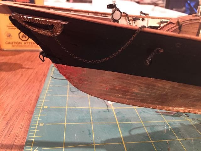
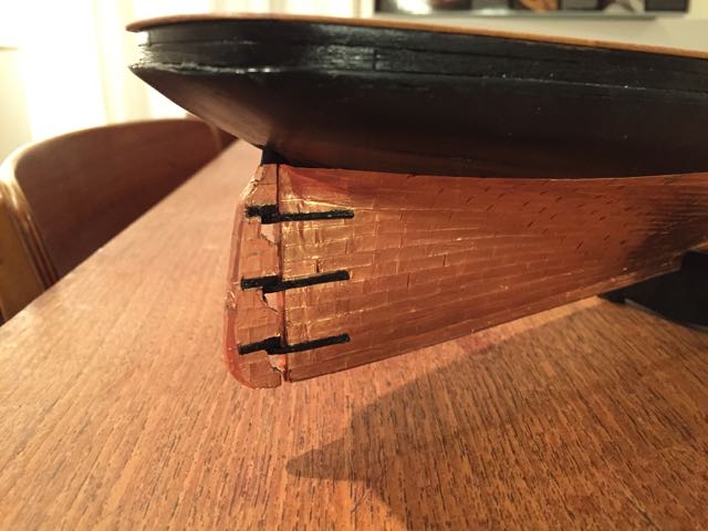
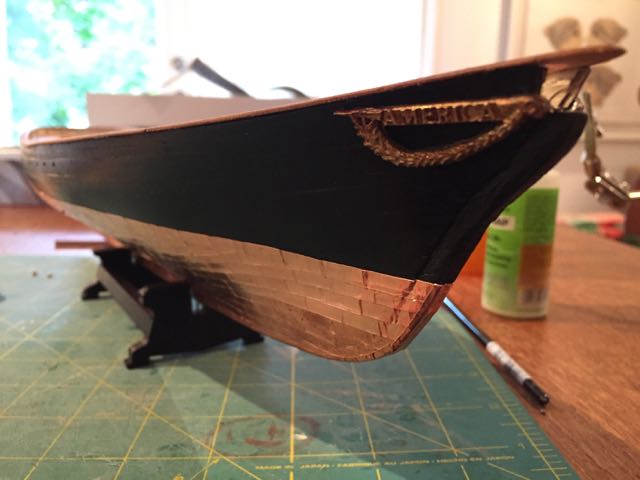
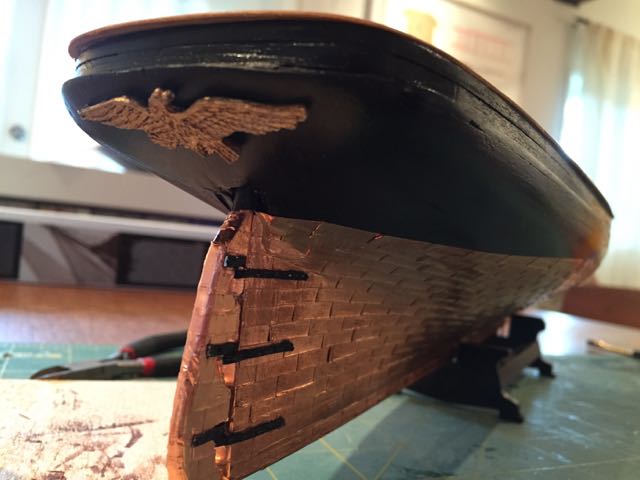
Hello there: I've made quite a bit of progress on America since the last update. I'll break this up into a few posts since there are some cursory things and some more detailed ones. First a few shots of nice but small progress -- the rudder and the outboard decorations. hamilton
-
This is really stunning work! hamilton