
HOLIDAY DONATION DRIVE - SUPPORT MSW - DO YOUR PART TO KEEP THIS GREAT FORUM GOING!
×


hamilton
-
Posts
1,931 -
Joined
-
Last visited
Content Type
Profiles
Forums
Gallery
Events
Everything posted by hamilton
-
The sad part about not including the laser cut templates is that it takes away the possibility of scratch building the kit - though I completely understand the logic. I'm building Syren right now, and one of the laser cut bulkheads (#4) had some gaps in the wood on the bulkhead extension, so I had to cut a new one - using the template - though I guess the part itself would have served. My wife runs a design business and she has had no end of problems with both foreign manufacturers AND European and American companies ripping off her designs - I have to say that in our experience this is not a phenomenon exclusive to Russia and China - it is in the very nature of Internet-based (or internet-facilitated) businesses. I have another friend who discovered that a song of his was being used in a Samsung commercial in S. Korea - without his permission. The payout he got allowed him to renovate his kitchen, but music publishing rights are pretty clear cut and enforceable. My wife, however, has been burned by some recognisable US, Swedish, Australian and UK companies as well.....her and her partner have had to become very savvy about licensing and copyright on the designs and on how they are marketed online - though access to the images themselves cannot prevent copycats from just biting their style. They modify one small aspect (like the layout of a set of graphic elements or the colour of an image) and call it "unique". The "creative" in "creative economy" is very widely interpreted, it seems.....and is even a possibility for those for whom "creativity" is just novel ways of thieving other people's labour.... hamilton
-
 The sail looks amazing! Way better than the ratty ones I made....I would love to see a detailed tutorial on your approach! hamilton
 -
I think the point of proportional dividers is to scale up and scale down, though they can be used to transfer lengths from plans to materials. I have a set of the micro-mark ones and I have not used them for kit building (though I have used them to practice lofting frames from plans - I can see how for a scratch build they would be very useful to have). hamilton
-
I'm sure you'll get up again Ferit! There's a thread somewhere on MSW about debonding glue - I'm not sure what you used to fix the mast, but you might try to find that thread....I'd do it for you, but my son needs reading and putting to bed.... hamilton
-
Hello Ferit!! It's so nice to see you strike this journal up again! Your Berlin has always been one of my favourite builds here on MSW. I'm sorry to see a bit of damage on the kit - I'm sure you will remake it to perfection. You may notice from my signature that I now have the Berlin kit on the waiting list....I've spent a few evenings looking through the kit contents and translating the Italian notes on the plans into English (strangely, my Italian has not improved as a result!) Anyway, I'm happy to see you back here and look forward to more updates on this beautiful build hamilton
-
Maybe someone's suggested this already, but since it takes long enough to build even an inexpensive model, you can use that time to squirrel away a bit of money for the next one. My first model was the MS Phantom which took 3 months to build and cost about $100. While I was building it, I put away 50$ a month and then used that to buy the Sultana which took me about 4 months to build - during which I saved 75$ a month for the next one....etc. Now I have basically budgeted some money every month that automatically goes into a savings account that I use exclusively to support the hobby - and I have a priority list of goodies - not many kits on the list anymore, just tools and such. From my perspective it's easier to save the money over time than to try to rationalise to the Admiral why I have to spend (at a poor Canadian exchange) 500 or so USD on a Byrnes saw or even 100 USD for a volume from the TFFM series.....but since patience is so necessary in this craft (though I'm not a naturally patient person) I can wait a little bit and treat myself once I've saved my shekels...If you can wait, even a $1000 kitty is not unattainable - as long as no one else (Admiral and Little Lubbers) goes wanting! hamilton
-
Hi Al: I'm sorry to hear about your wife's health - it can't be easy and I hope she's doing ok and that you're taking care of yourself. Best for the new year to you both hamilton
-
Hi Peter! Happy New Year. The ship's boat looks great - have you decided how to add it? I haven't seen any images that might act as guidance but if I come across any I'll send them your way.... hamilton
-
Excellent work Tim! Love the coppering and the special sans-sails rigging! I'm looking forward to following your Cutty Sark when the time comes - hope you have a great holiday and bye for now! hamilton
-
Hi Tim: She's looking really great! Nice work on the rigging - the "fake" running rigging shows some interesting set-ups. Well done hamilton
-
Like the way you set up the topmast backstays - I followed the kit plans but I think yours look much better! hamilton
-
Alright Tim! I've also rigged ships without sails in the way you describe (most recently the Fair Rosamund). I think either way is acceptable. As for Syren - I have had the bandsaw out!! I had to cut a new bulkhead because one of the kit-supplied ones had really bad wood - big old holes in the face of an already-fragile bulkhead extension....the new one works great and is very solid - if I had enough 3/16" ply I'd have remade them all, but I need my supply for the Bluenose when I finally get back to her in the Spring....Syren is slow moving, but I've started on the gunport framing (last night, which was my first night modelling in almost a month!)....anyway, looking forward to more updates here hamilton
-
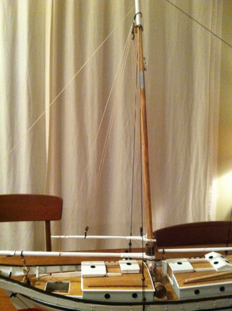
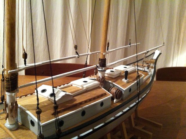
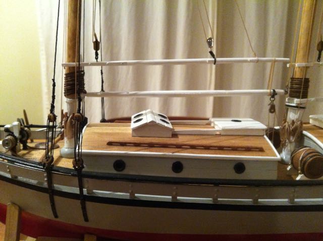
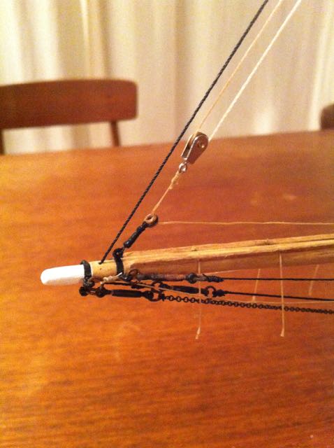
Hi Tim: Here are a couple of pictures of my Glad Tidings to illustrate some running rigging with no sails - peak and throat halliards are included on the gaffs, but you can see they're lowered to deck. Forward I also included the jibsail running rigging (halliard & downhaul anyway). I imagined (perhaps incorrectly) that the gaffs and booms would be lashed together (though this was "modeller's convenience" since I didn't want the gaffs floating free on the horizontal and wagging back and forth). With America this would be tricky with the fore gaff since there's no boom....I'm really not sure how you would fix it, except at the jaws. On some of my early models, I set a small rod at the fwd end of the gaffs and then drilled a hole into the mast to receive it - this would fix the gaff and provide extra support and reduce any lateral movement....Anyway, hope you don't mind me posting the pictures here..... hamilton
-
Good to see an update here Tim! She's looking spectacular! I like the optical illusion in one of the photos of the tweezers floating in the bowsprit rigging! Had to widen and narrow my eyes a few times to correct for it! Anyway, the rigging looks great - really brings her to life! Looking forward to more hamilton
-
Looks great Peter - I found the holes on the belaying racks to be too small on mine as well. But instead of trying to widen the holes (didn't want to try after my experience with the deadeye strops) I sanded the belaying pins themselves to be a little thinner....Anyway, the masts look really nice - she's shaping up very well hamilton PS - where I am in Canada there is maple, but not much - mostly softwood here - back east it's much more plentiful h
-
Planking looks really nice Andy! Too bad about being away from the bench, but I guess the bacon needs to be brought home, eh? Have fun! hamilton
-
Looking good Peter - the stand looks very nice - I just used the one that came with the kit....yours is much nicer hamilton
-
Hi Peter: Actually once the deadeyes/chainplates were attached to the hull there was no issue. But one modification I made to the chainplates (not sure if you did this) was to snip off the mounting pegs on the back side of the chainplates and just glue them directly to the hull with a small amount of epoxy. I was a little nervous that they wouldn't hold, but in the end they were fine and there was no snapping or breaking of these small parts....thankfully! The Syren is moving slowly! It's a really busy time at work, so not much modelling getting done at all. I did have to cut a new bulkhead because one of the ones provided in the kit had a great big gap running along the edge, weakening it considerably. Fortunately, I have a decentl supply of 3/16" maple ply lying around from my Bluenose scratch build that I could easily cut a new one. I've now gotten to the point of assembling the basic framework and rough fairing the hull. When I'm able to get back to it, I'll be starting on the gunport framing.....I might post a casual log once my plate clears at work.....perhaps over the Christmas holidays.....in the meantime, I'll just enjoy your build and others on this forum! hamilton
-
Looks really beautiful John - you should be proud! I love the choice to show the forward port side whaleboat being launched - a classy touch! On the the next? And what will that be? hamilton
-
Hi Peter: Looking good - I found those deadeye strops to be way too soft! I ended up breaking one and improvised a repair by using a modified gudgeon leftover from my HMS Blandford....it's on the non-display side of the model so it's not too offensive. You obviously were more careful with yours than I was! hamilton
-
Hi Chris: Are you following the planking expansion that ME provides as a plan sheet with this kit? So far your planking looks good, but when I was reading about your woes earlier on, I wondered if you were following their scheme or spiling the planks on your own.... Where the plank edges are exposed, you should use a scalpel blade (#10 x-acto) to "take the edge off" and then sand liberally to get a nice smooth hull. Keep on going my friend!! hamilton
-
Hi Chris: Per's right - there is little space between the bulkheads! But I think you'll find that this makes fairing and planking quite a bit easier. I built this kit a couple of years ago and it still stands out as one of my very favourite builds - lots of fun and at a large scale that allows for some interesting detailing. Looking forward to seeing yours come together and happy to answer any questions you might have as you go through the build (if I can remember!) hamilton
