shipmodel
-
Posts
941 -
Joined
-
Last visited
Content Type
Profiles
Forums
Gallery
Events
Everything posted by shipmodel
-
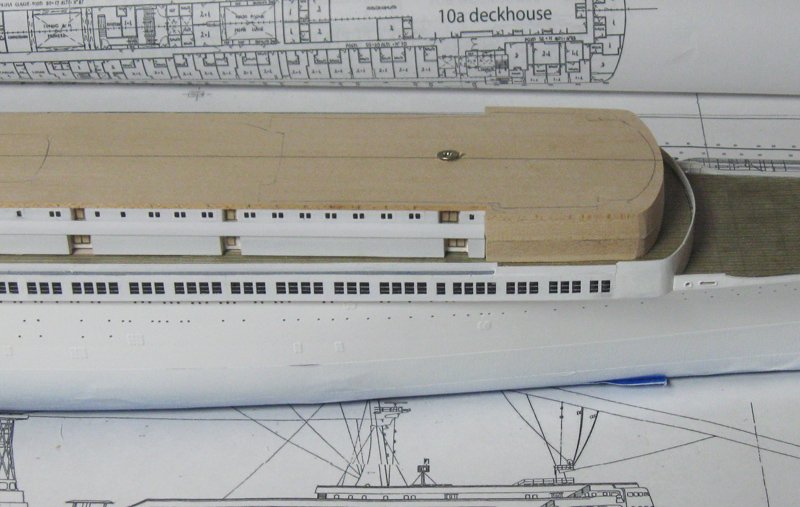
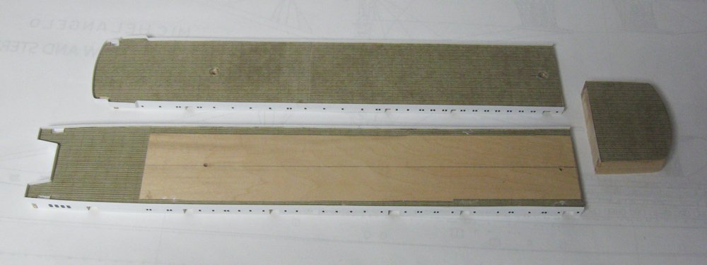
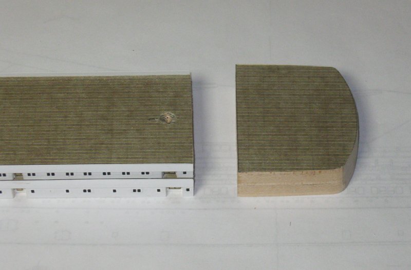
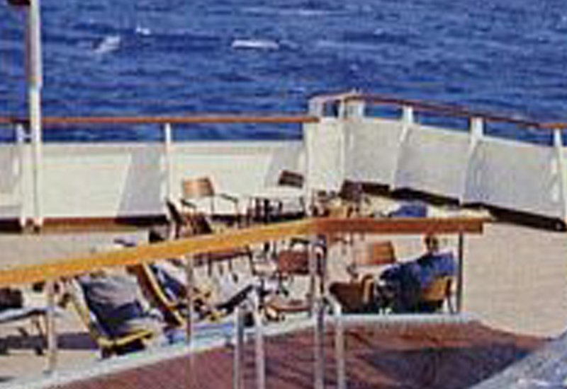
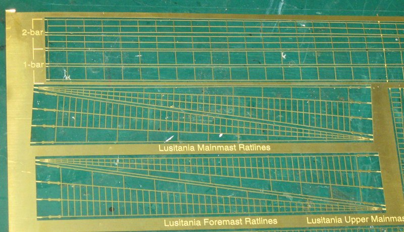
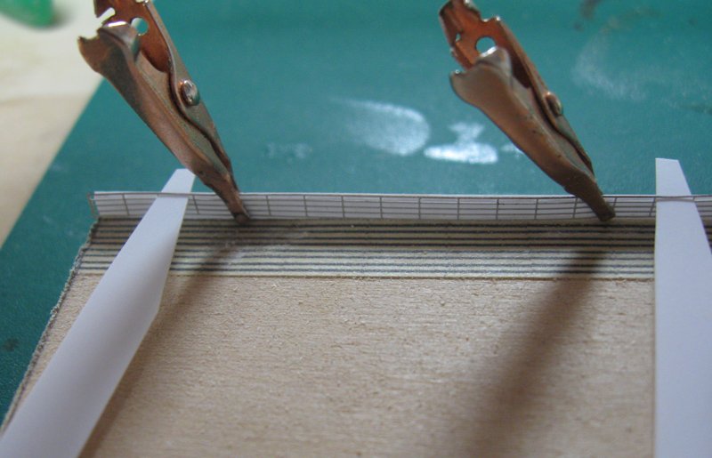
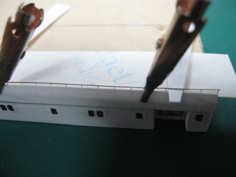
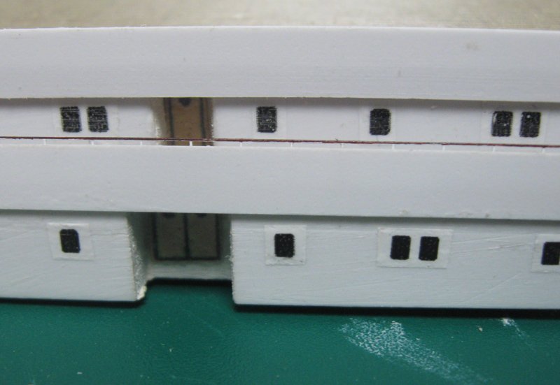
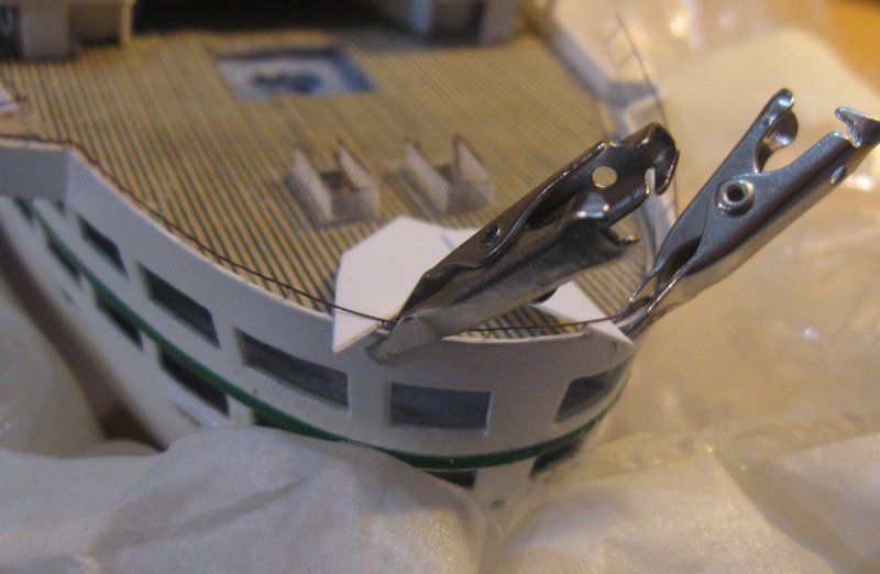
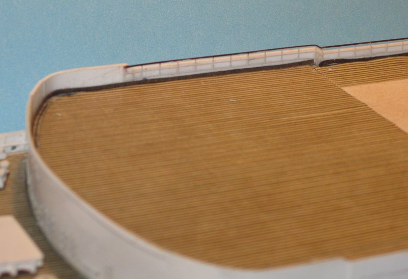
 Hi all – I hope everyone is recovering from a happy Thanksgiving, or Autumn festival of your choice (John, do you still call it Autumn down under, or is it Spring?) Now that the boot topping and working bow deck were done, I went back to figuring out how to best work on the deckhouse details for the Boat and Superior decks, which had to be done separately because the setbacks were so narrow, while at the same time their bow sections had to be worked on together because their sides were flush. Here is how the decks stacked up last September. I drilled and screwed them together to rough out the bow sections, but this was not as repeatable as I needed to work on the flush surfaces. I decided that the only way this would work was to carefully cut the bow section off each deckhouse. It protrudes a little athwartships, so there is a natural separation point. I marked out a line perpendicular to the centerline using some basic geometry then cut along it, slowly and carefully, with my band saw. The rough edges from the cuts were smoothed with a disc sander. I glued the forward pieces together and will shape and fit them out later. The two deckhouses are stacked together but remain unglued. Now I turned to the railings around each deck. In the first photo you can see how the solid railings are surmounted by a wooden handrail supported by single flanges that lead down to the deck. There are no crossbar railings at all. The base of the railing has a brown margin at the deck. The handrail is fairly high to keep passengers from falling over. Judging from the postures of the passengers I estimated that this is about 44”. That is, 36” for the solid rail, and another 8” for the handrail. The closest I could get to this configuration was on the photoetch (PE) fret from Gold Medal Models. On their ‘Merchant Ship’ sheet there are two lengths of 1-bar railing which have only the top handrail and bottom base rails with no cross rails. The rest of the railings are 2, 3, 4 and even 5-bar. I bought three sets, despite the cost, but six lengths would not be enough for the whole model so it was saved for the most visible areas. But where the back of the railing was hidden by an upper deckhouse, I used 2-bar PE. To get a consistent handrail height above the solid railing I cut two tapered strips of 0.02” plastic and slipped them through the PE under the handrail as spacers. 0.02” is 7” in scale, so when the strips rested on the solid railing the handrail was just the right height above it. The PE was carefully positioned and clamped in place with smooth-jawed electrical clips. The above photo was taken while I was working out the method, so I just used some excess 4-bar railing, but the technique worked as well with fewer crossbars. Here is what the setup looked like from outboard. With a section held in place, small drops of thin cyano on a toothpick were touched to the PE to hold it to the solid railing. When the glue was dry the spacers and clips were moved along and another section was done. Tension was maintained during the gluing process, and the result was a very straight, consistent handrail. Here it is with the Superior deck house set in place for contrast. When the cyano was fully dry the entire length of the railing was overpainted with white glue. I like this double security. The cyano gives the joint strength, while the white glue gives it some flexibility and shock absorbing qualities. Having worked out the method, I turned to the tricky section of railing around the stern deck. Not only did the railing have to curve, but the railing leaned outward a bit. This conic shape meant that the PE would have to bend in three dimensions, which it cannot do. I ruined the first length of the scarce 1-bar railing trying to make it bend. Ultimately I had to carefully cut the base rail every other section and work slowly and carefully around the curve. I learned from my mistakes and the second fitting of handrails here was satisfactory. For the brown base of the railing I cut narrow strips of acid free art paper, soaked them in dilute white glue, and laid them around the perimeter of the rails. This not only matched the photos, but hid some uneven spots caused by the cut base rails. Using these methods the railings were installed around the perimeter of the Promenade and Boat decks. Next segment will cover the final detailing of the Boat deck house and its installation on the model. I will try to get it posted before the holidays. If I do not post before then, a healthy and happy Holiday Season to one and all, and a very good New Year. Dan
- 287 replies
-
- 15
-

-
- michelangelo
- ocean liner
- (and 1 more)
-
Hi Adrian - That is some beautiful, careful work that you are doing, and using a method that I haven't seen before. Do I understand correctly that you are plating the inside of the hull? Dan
-
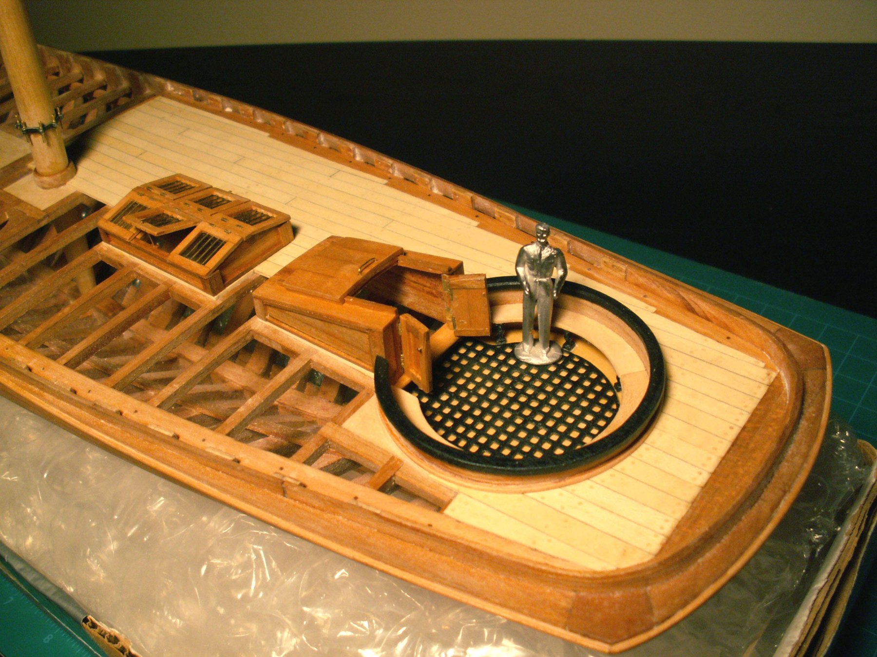
Hi Charlie - She's coming along nicely. The pivot circle for the carronade is a difficult piece, and you have done it well. On the deckhouse, I don't know what you mean by "The back will be raised a bit so the little guy can go in." It looks good to me. The companionway hatch cover will slide forward on a pair of rails, which will give the man the room he needs to go down the companionway steps. There were probably a pair of doors that closed off the aft end of the deckhouse when not in use. Something like this - Hope that helps. Dan

- 362 replies
-
- 8
-
-
- active
- revenue cutter
- (and 1 more)
-
Hi Charlie - Putting on my shipwright's cap, here's my two cents: The 'flashing' is not so much to keep water out of the galley as it is to stabilize the chimney coming off the stove. It would need some support as it goes up through the deck, and a strong metal plate secured to the grating would fit the bill. Any sort of wooden support would get too hot, I think. When it rained, the tarp that appears in one of the Mamoli photos could be used (although I am a bit wary of relying on a detail from a model where the gratings do not have a solid perimeter). As for the direction of the top of the Charlie Noble, pretty much any orientation is OK, since they turned to stay out of the windstream. Use your best artistic judgement. In the real world, sideways to the wind was probably best, since it would pull the smoke most strongly up the chimney, like blowing across the top of a straw. They just had to be sure not to face it into the wind, or the smoke would be blown right back down. The carronade and pivot mount are coming along nicely. Happy Thanksgiving to one and all. Dan
- 31 replies
-
- 2
-
-
- ventilator
- flue
- (and 4 more)
-
Maury - The new rudder looks great. Sorry if my post had you doing extra work, but the improvement is noticeable. Happy Thanksgiving to you and yours. Dan
- 525 replies
-
- 2
-
-
- anchor hoy
- hoy
- (and 1 more)
-
If you trust your skill in softening the pieces, could you try to stretch them a bit? This would lengthen them and also flatten the arc. Does that make sense for the kit? Dan
- 2,699 replies
-
- 3
-
-
- heller
- soleil royal
- (and 9 more)
-
Marc - Very nice solutions to the fitting issues. As has been said, those few slight kinks in the run of plans and wales will never be noticed behind the headrails and rigging. Well done! Dan
- 2,699 replies
-
- 3
-
-
- heller
- soleil royal
- (and 9 more)
-
Thanks John, Nils, Marc, and Keith, and everyone who liked what I have done so far. This build has turned out to be much more interesting than expected, and I trust that it is presenting some information and techniques that are not so usual for this site. Dan
- 287 replies
-
- 6
-
-
- michelangelo
- ocean liner
- (and 1 more)
-
Hi Maury - Really nice work on an unusual subject. I like how the deck beams and underlying structure is shown, and how clean your masting is coming along. I do have a bit of an issue with your rudder. I may be mistaken, but with the angle that appears to exist between the rudder blade and the rudder head, I do not think that your rudder can turn. With this kink, as the rudder blade pivots on the pintles and gudgeons, the rudder head would have to move in an arc, side to side. But you have the rudder head going through a large block that fits tightly around the rudder head, giving it nowhere to move. This may be an artifact of the photograph, but you probably should check it. Dan
- 525 replies
-
- 2
-
-
- anchor hoy
- hoy
- (and 1 more)
-
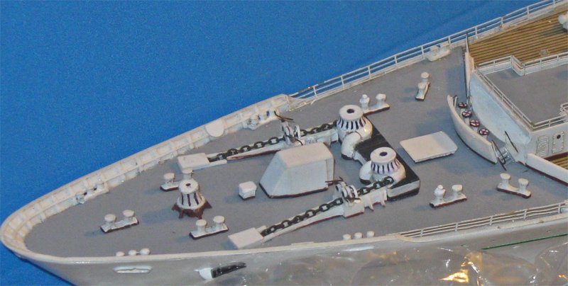
Hi again to everyone following or looking in - So I did, ultimately, cut the anchor winch platform in half and insert a 4mm matching piece in between. Like the rest of the platform it is a sandwich of 2mm hardwood with a top layer of 0.05” black plastic. The bottom was ground to the proper slope angle and glued to the deck and to the winches. The chain stoppers were further reduced in size by about 20%, and maybe a bit more on the handles. Now the threaded rod is 0.025” and the handles are 0.009” wire. For the hawse hole covers I made them up as a frame with a flat cover without any details. I decided that simplicity was best here since I still do not know exactly what they looked like. The changes are not especially noticeable, but in comparison I think they match just a bit better to the actual ship layout. So here is the bow deck complete with the fittings secured. I also added the small rounded platforms for the mate to stand on when mooring the ship. You can see the starboard one stowed against the bulwark just above the hawse cover. It flips up and extends out past the bulwark edge to give him full view of the dock and the ship. You can see it extended in the photo of the ship, above. The final fitting is a platform and railing at the extreme bow, with the ensign staff mounted in it. I felt that it was too exposed and likely to catch my careless fingers, so it will be installed near the end of the build. And here is a view of the entire working deck. Nothing in it draws my eye as being out of scale, so I am content for the moment. I hope everyone is equally content with their projects, and that you and your families all enjoy a healthy and happy Thanksgiving. Dan
- 287 replies
-
- 16
-
-
- michelangelo
- ocean liner
- (and 1 more)
-
Congratulation! Glad it came out so well for you. Looking forward to the photos. Dan
- 2,699 replies
-
- 3
-
-
- heller
- soleil royal
- (and 9 more)
-
Hi Marc - My experience with plastic is that most of the stuff used by kit makers will resist softening until it is right on the edge of melting. Once melted, there is no going back. I would start out with the most gentle heat I could apply. The quickest to try would be Joyce's hair dryer on the lowest setting, and just up the power if it doesn't work at first. But I remember that when my eyeglasses are fitted they often dip the earpieces in hot sand. That would be my next experiment. You might also make kerf slots in the plastic of the interior side of the hull piece that you are trying to bend. It will make the bending go a lot easier, whether you are trying to open up the curve or close it. Dan
- 2,699 replies
-
- 3
-
-
- heller
- soleil royal
- (and 9 more)
-
Hi all - Thanks for the likes and comments, and especially to John for the explanation of hawse pipe covers. i didn't know such a thing existed, but it makes perfect sense. I did a quick search for an image, but only found examples for much smaller boats. I am sure a photo exists, but I haven't found one yet. Dan
- 287 replies
-
- 4
-
-
- michelangelo
- ocean liner
- (and 1 more)
-
Really nice work. I am very jealous of your masking and painting expertise. Hope those rails work out for you. Dan
-
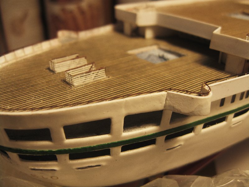
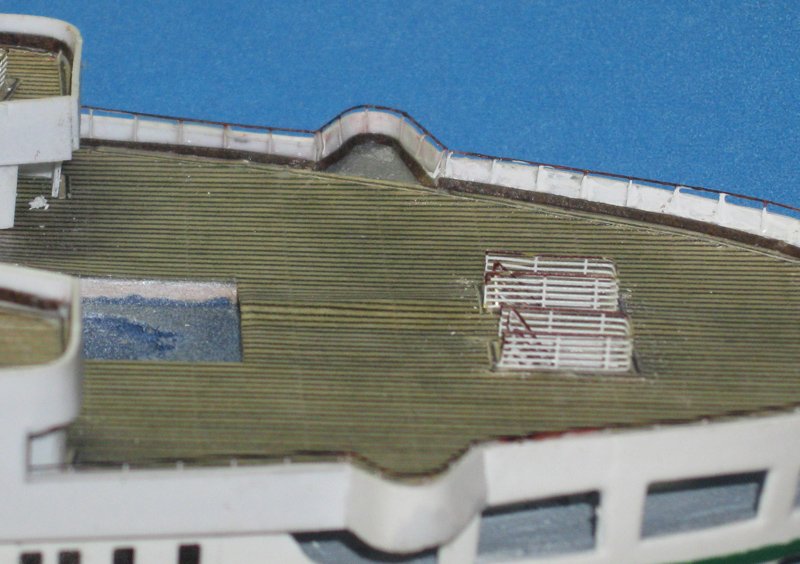
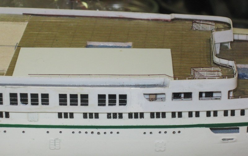
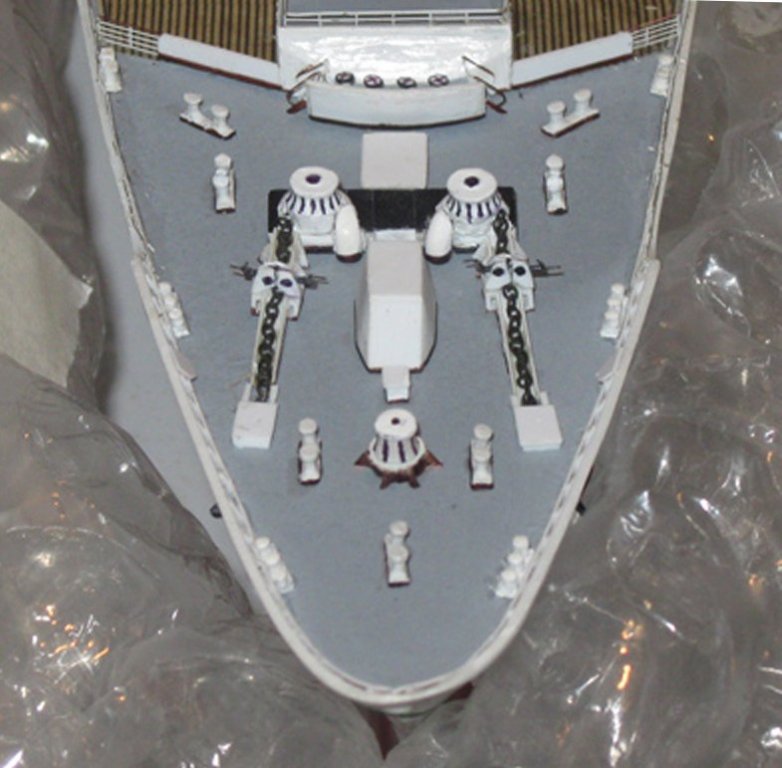
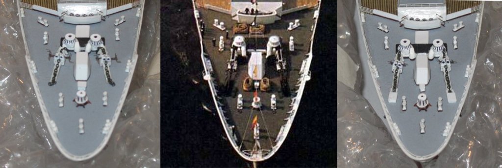
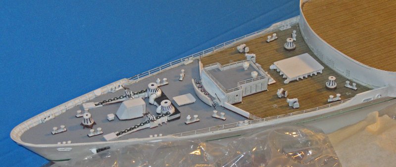
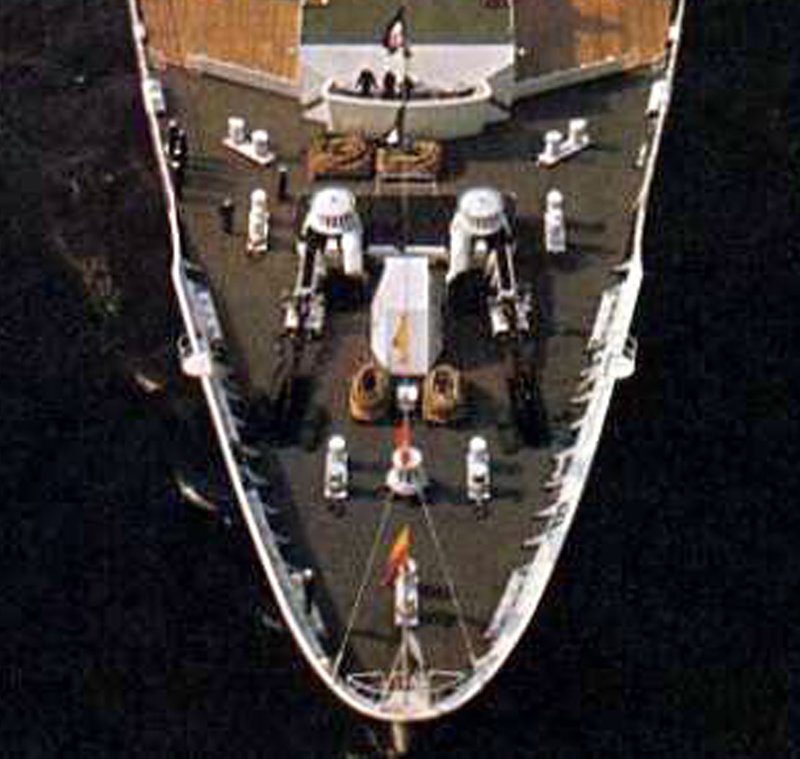
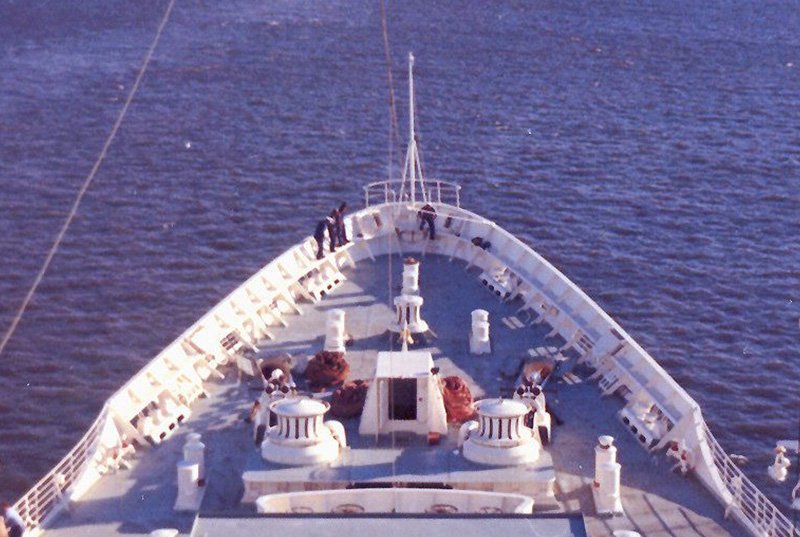
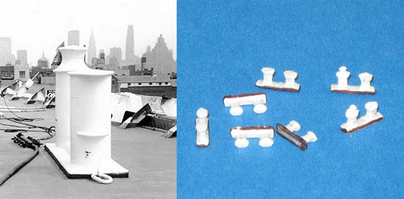
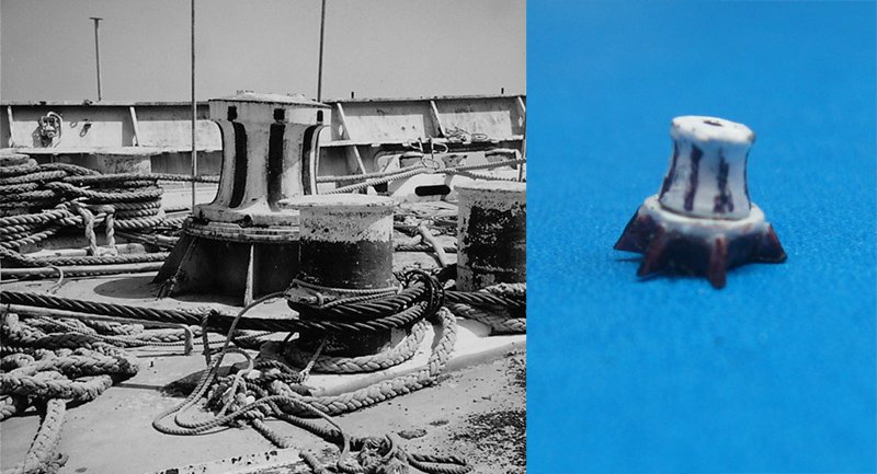
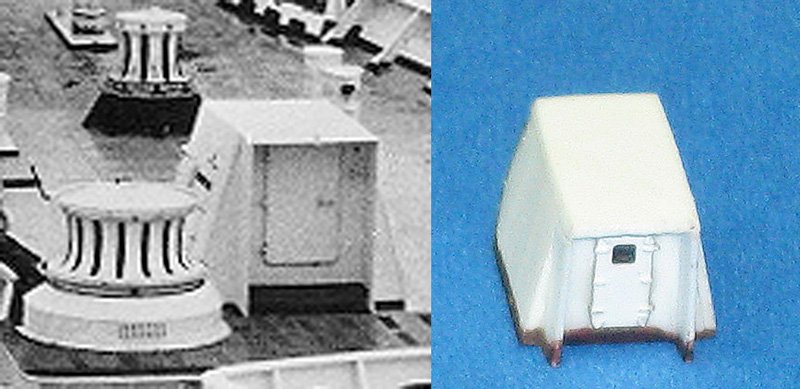
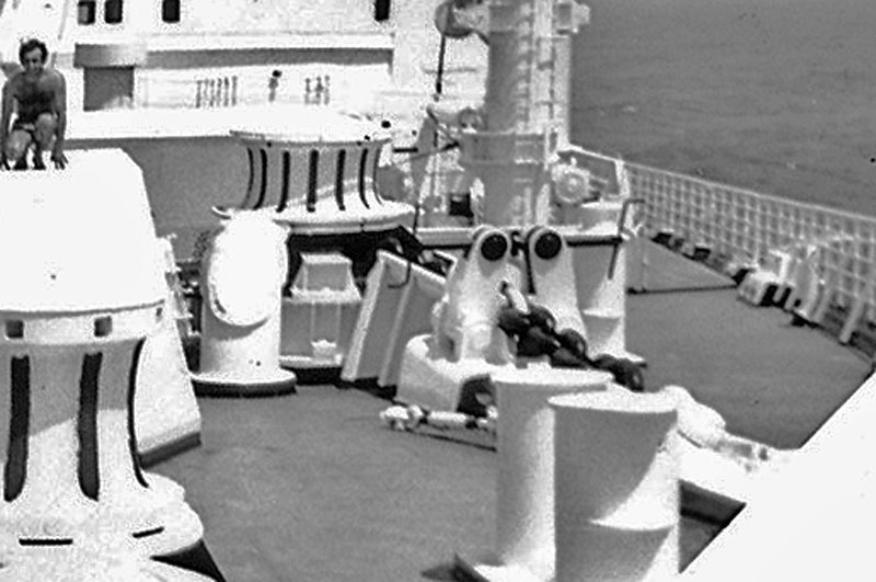
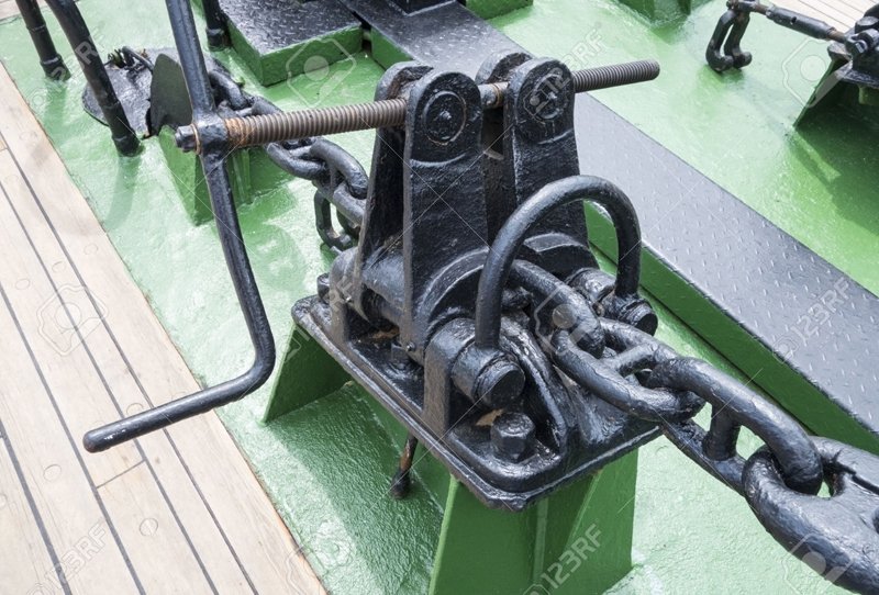
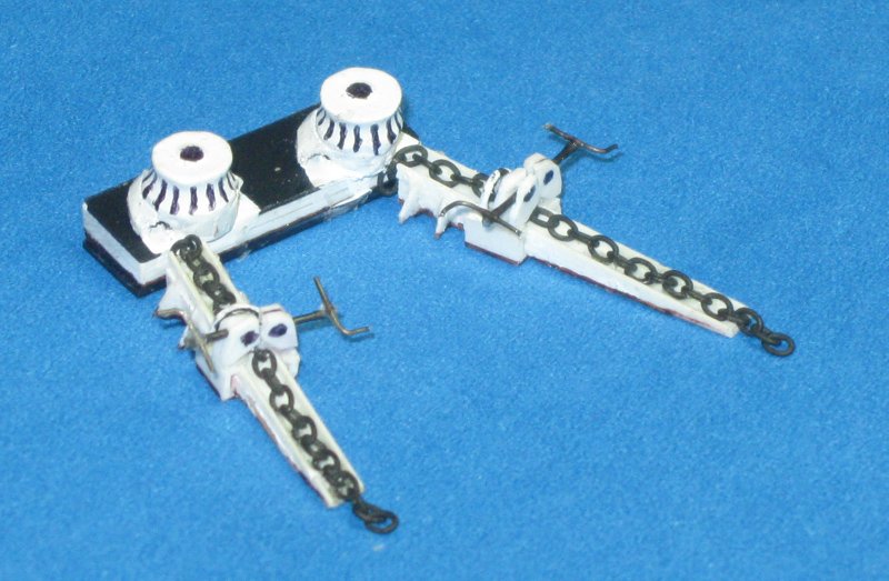
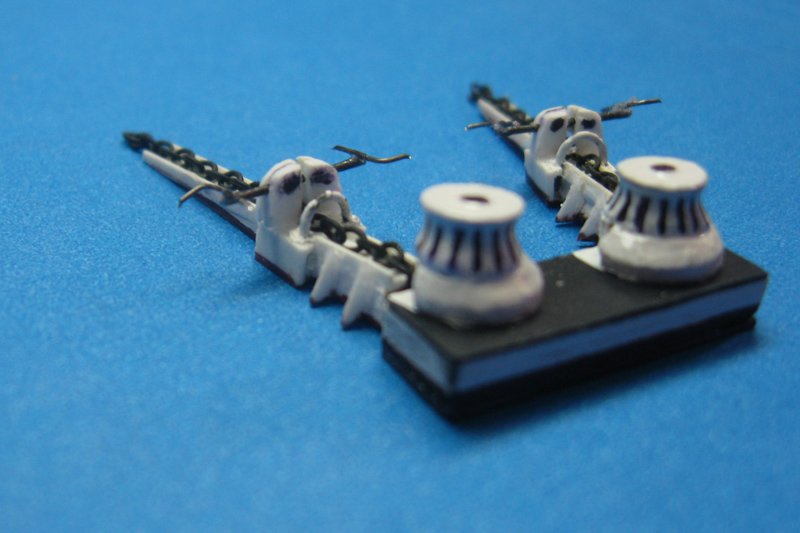
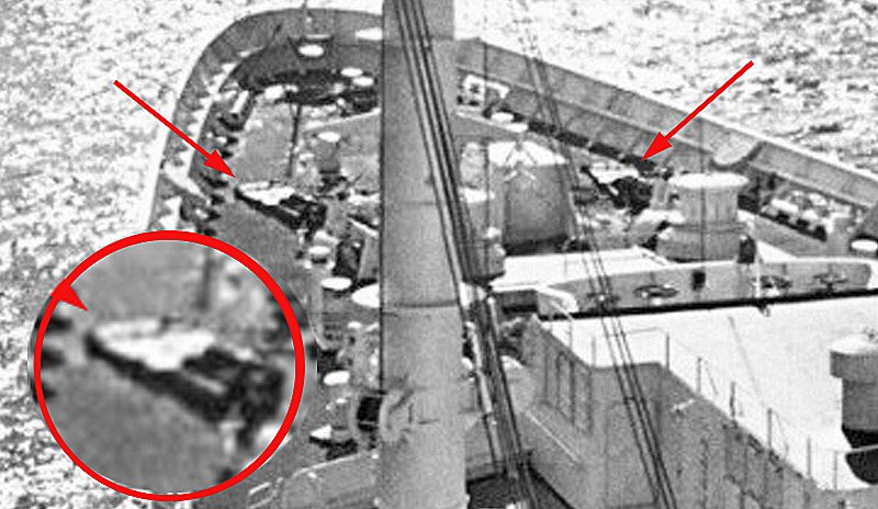
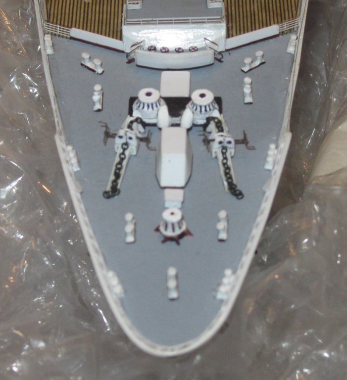
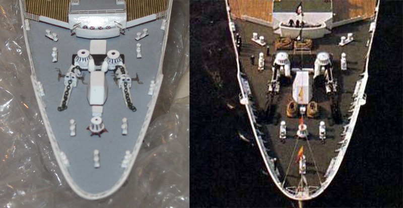
Hi all - Here is the next step in the journey. With the wooden decked portion of the bow deck done, I moved on to the forward area which was covered in just a composite waterproof material. This area housed the ground tackle – the anchor machinery and the mooring equipment and lines. Its color is quite variable. In the first photo it looks dark brown, while in the second is a light grey, while another is a pinkish tan. The medium grey is the most common, so that is what I went with. Some of the fittings here are familiar. Five of the seven bollards are the same as on the cargo area of the deck, but the two which flank the anchor winches have small nipples on the forward posts. Here is a photo from the ship, taken in NY harbor after the wave damage, and the fittings for the model with the two unusual bollards to the right. The small mooring winch is similar to the two on the cargo deck, but the base is different. In the photo, taken at the breakers’ yard, it is supported on a flanges and looks like it leans forward. In fact the winch is vertical, the tilt is just to compensate for the upward sheer of the deck. The model fitting was built up from a metal casting, a wooden base and styrene flanges. The photo showed me that it needed some more touch-ups before final installation. In the center of the deck is a companionway leading down into the engineering spaces under the deck. It has a complex shape, with angled sides and an angled forward face. There is a doorway on the aft face that is framed by protective barriers. You can see it in the two overall photos at the beginning of the segment, and here is a close-up. After a few initial missteps, the model piece was built up from a wooden core with my usual styrene sheathing and photoetched door. The most complicated bits of machinery on this deck are the two anchor chain winches. They are not detailed at all on the plans, so a great deal of information had to be gleaned from the photographs. Unfortunately, very few showed these features from viewpoints that would have yielded a complete idea of what they looked like. You can get the general look from the two overall photos, above, and here is a bit closer view from ahead. After studying these and other photos, I believe I know most of the details. The machinery seems to consist of two large round winch heads that sit on a wide raised platform. Like the base of the small winch, this platform tilts forward relative to the deck so the winch heads are vertical. A sloping ramp leads the chain up from the hawse hole and into a covered tunnel under the winch head where it is pulled around and then fed inside a large elbow and down into the cable tier. Along the way it is straddled by a fitting with two vertical arms that are connected by a bar with some sort of handles on each end. I found out that these are called chain stoppers, whose purpose is to clamp onto the chain and take the strain off of the winch from the weight of the anchor. Here is a smaller one, but the elements are the same, and it is easier to understand what is going on. You can see how turning the handle would turn the bar with opposing threads, closing or opening the hinged arms to trap or release the chain. So here is my latest iteration of the machinery. Each element was built up from whatever materials came to hand, including hardwoods for the platform and ramp bases, plastic channel for the tops of the ramps, wood and metal for the winch heads, bits of plastic for the base and arms of the chain stopper, and iron wire for the threaded bar and handles. The ramps are not yet attached to the winch platform, so the chain does not connect them. This will be done at final installation. There is one feature which I could not figure out. The photos show that the hawse holes are not simple ovals with lips, but seem to have some sort of covering. Unfortunately, this is the most detailed photo I found of the fitting. I will keep hunting, but if nothing further is available, I will fake it as I make it. So here is my first dry fit of all the components except the hawse holes. I added the chain return elbows to the anchor winches and set the fittings in place. Everything seems to fit pretty well and they tell a convincing story of how the ground tackle was laid out. However, when compared to the photo, and although I am getting close, there are some significant issues. The biggest is that the anchor winch heads are too close together. I am still debating whether to cut the platform along the centerline and piece in to make it wider. Is this too much work, and too risky, for not much gain? Also, the chain stoppers are still a bit overlarge and clunky, especially the handles. Is this getting too picky in a component that is barely a quarter inch across? Final details and improvements – or not – next time. Be well. Dan
- 287 replies
-
- 8
-
-
- michelangelo
- ocean liner
- (and 1 more)
-
Hi Ken - The rails in Tom's 3501 set are all 0.125". I also have his 3584 (IJN 2-bar rail) whose rails are slightly less at 0.120". I do not have 3583. Gold Medal Models merchant ship fret has rails also of 0.120". GMM's fret is much larger than Tom's so the rail lengths are longer and there are more ladders and stairways as well. I have had great customer service from both Loren Perry at GMM and Rich Harden at Tom's. Don't know what your communication problems are. Try Rich again at tomsmodelworks@aol.com Hope that helps and best of success, the model is turning out beautifully. Dan
-
Hi Ken - Really nice work on the bow thruster. Your progress has been really captivating. I am working with photoetched railings in 1/350 from both Tom's Modelworks and Gold Medal Models. What do you need to know? Dan
-
Keith - As a student of rigging and its techniques, it is a pleasure to watch you work. Dan
-
Hi guys - Glad you liked the tale of the great wave. Sometimes it is pointed to as a piece of the reason why the liners gave way to the airlines. For me, the story of the hubris of John Stienbach and his swift karmic punishment is another small facet of the wide, wild, wacky, woeful, and wonderful diamond that is the human experience. Preserving these stories in three dimensions is one of the central reasons why I choose to model ships. As for the small scale, Keith, it is all done with lots of magnification and lots of light. Glad that the photos let you enjoy the nano-journey. Dan
- 287 replies
-
- 4
-
-
- michelangelo
- ocean liner
- (and 1 more)
-
I don't know if you will have to make any more cuts like those, but if you do, a razor saw with a wide blade is your friend here. Dan
- 2,699 replies
-
- 5
-
-
- heller
- soleil royal
- (and 9 more)
-
Hi Mark - Good to see you back. Progress is looking good. As for the sanding wheel, that is an ingenious solution to the problem. I did not think of it, but bought flap-wheel sanders from Dremel - Product EZ474SA gives you both a fine and a coarse wheel for under $8 at Amazon. I have them and they are wonderful to use once you get used to using a light touch. Dan
-
Hi Nils - Good catch on the twist. Check, check, and then check again usually works. If I may suggest - mist with water the areas subject to the greatest torque while they are under strain from your weight. That might help the wood accept the new configuration and lessen the tendency to spring back over time. To check, lay several rods across the bulwarks perpendicular to the centerline. I have always called these 'winding sticks' although I do not know where the term came from. Sight over the tops of the sticks and they should all be parallel to each other. Otherwise, excellent progress. I am thoroughly enjoying watching your build as it goes forward. Dan
- 692 replies
-
- 7
-
-
- eagle of algier
- chebec
- (and 2 more)
-
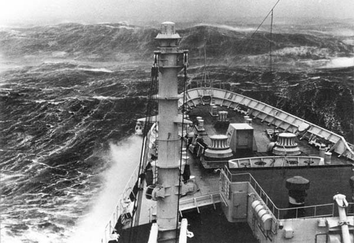
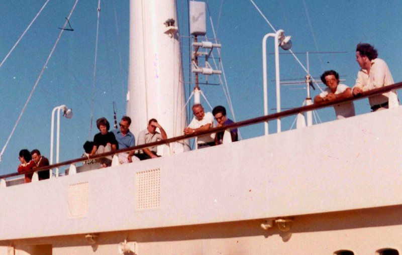
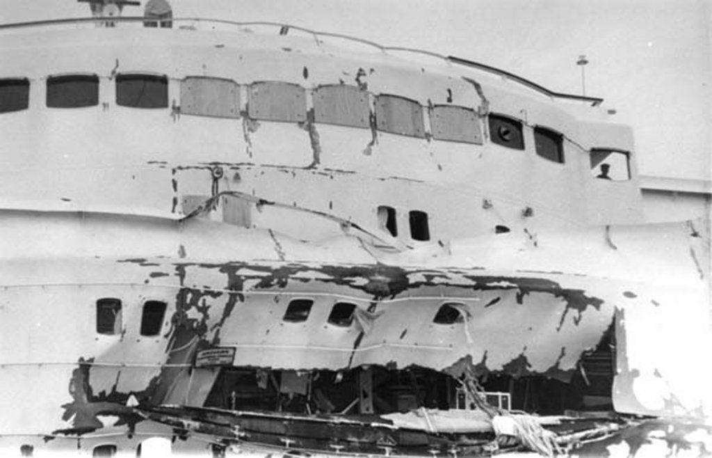
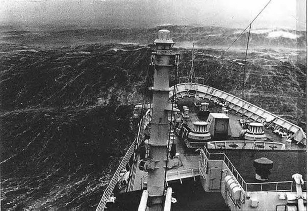
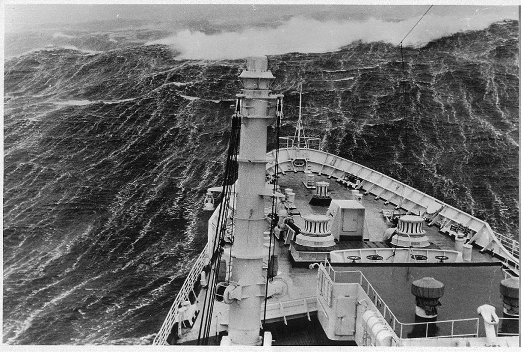
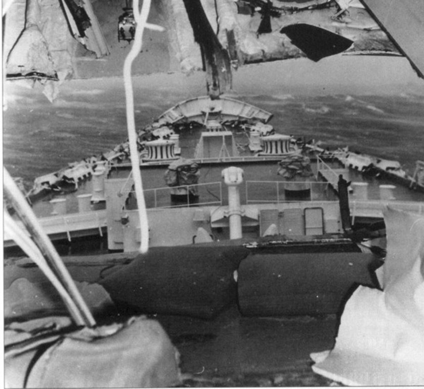
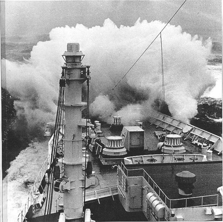
Hi Pat, Druxey - Well, whether a breakwater or not, it famously did not do its job. I was going to tell this story later, but this seems a perfect segue - - - On April 9, 1966 the Michelangelo left Genoa on a routine cruise to New York City with 775 passengers including German novelist Gunter Grass and the creator of Archie comics, Bob Montana. After stops at Cannes and Gibraltar it turned into the Atlantic at its normal cruising speed of 26 knots - and directly into the path of a hurricane. The weather worsened quickly and steadily and by the morning of Tuesday the 12th the ship was being tossed around like a toy, despite significantly reducing speed. The ship shuddered every time the huge rollers slammed into the bow. Terrified children screamed and clutched their parents, who were not any less scared. Anyone trying to take comfort in any of the lounges faced injury from tables and chairs being thrown across the room. Bob Montana recalled, “The waves looked like apartment buildings. I was worried about how much the ship could take. The ship was not just rolling and pitching – it shuddered. Things jumped, everything fell onto the floor.” At around 10:00 a passenger, John Stienbach of Chicago, dared other passengers in the first class lounge to join him in his suite which had windows in the forward superstructure facing the bow. No one took him up on his challenge, so he went alone. Twenty minutes later the ship lifted on another huge wave and dove into the trough behind it. Before it could lift the following wave, a huge 60-foot wall of water, crashed over the bow – tearing over the puny breakwater – and slammed into the face of the superstructure. All of the forward facing windows were blown out in a hail of glass shards which injured, among others, the captain on the bridge some 70 feet above the deck. John Stienbach was killed instantly. Two others died of their injuries and 50 more were injured but survived. Someone, possibly even Stienbach himself, took a series of photos of the bow driving into the waves. This is not the fatal wave, but you get the sense of what it must have been like. It is ironic that these are some of the best photos for determining the exact details of the fittings on the bow deck: The superstructure below the wheelhouse was buckled and caved-in by the force of the tons and tons of driving water. The ship’s stem was bent backwards while metal bulwarks and over 100 feet of railing were ripped out of the deck and carried into the sea. Damage to the interior cabins, lounges and saloons was massive. The aluminum skin of the ship was ripped open and a hole appeared in the forward bulkhead 45 feet wide and three decks in height. The open deck at the bow had various fittings, strong enough to handle the anchors and mooring cables, torn loose or damaged. In this photo taken from inside one of the lounges you can see how the port bulwark is damaged and the starboard bulwark has been ripped away. Four days later, with the damage to the bow mostly hidden by a tarpaulin, she limped into New York harbor and into her pier. After disembarking all of the injured to ambulances the shaky passengers went down the gangways and the ship went to the Bethlehem Steel shipyard in Hoboken where 115 craftsmen worked around the clock to make repairs. In only four days the ship was ready to embark passengers again for a return trip to Italy. Of the shipyard workers, Michelangelo’s captain would say, “They worked beyond expectancy, so quickly without giving us any problems – they just did it.” The ship continued in the trans-Atlantic trade for another nine years until the governmental subsidies which had kept the Italian Line running dried up. Like many other obsolete luxury liners she was considered as a hotel, as a yacht for billionaires, but was ultimately purchased as a barracks ship for the Shah of Iran in 1977. She outlived her purchaser, but in 1991 she met her end on a breaker’s beach in Pakistan. Sic transit gloria mundi. So passes the glory of the world. Dan

- 287 replies
-
- 10
-
-
- michelangelo
- ocean liner
- (and 1 more)
-
Druxey - "Two peoples divided by a common language . . . " W. Churchill Dan
- 287 replies
-
- 4
-
-
- michelangelo
- ocean liner
- (and 1 more)