HOLIDAY DONATION DRIVE - SUPPORT MSW - DO YOUR PART TO KEEP THIS GREAT FORUM GOING! (Only 24 donations so far out of 49,000 members - C'mon guys!)
×


shipmodel
-
Posts
941 -
Joined
-
Last visited
Content Type
Profiles
Forums
Gallery
Events
Everything posted by shipmodel
-
 Hi Marc, Jan - If French practice at the end of the 17th Century is any guide, the hull planks were fastened with alternating wooden treenails and iron bolts. At butt ends I suspect that two bolts would have been used in the more problematic areas under strain. Not a definitive answer, but highly probable. Dan
- 2,696 replies
-
- 3
-

-
- heller
- soleil royal
- (and 9 more)
-
Le Soleil Royal by Nek0 - 1/72 - Marc Yeu
shipmodel replied to Nek0's topic in - Build logs for subjects built 1501 - 1750
Hi Marc - Thank you for posting photos of your outstanding work. You are clearly a very accomplished draughtsman and woodworker, and your model is well on its way to being a top notch work. I will be following along with great interest. It will also be very informative to compare and contrast your work with Hubac Historian's plastic model, and Michel Saulnier's as well. I may never build one of these massive projects, but I will learn a great deal from all of your efforts. Thanks again. Dan- 208 replies
-
- 5
-
-
- le soleil royal
- 104 guns
- (and 2 more)
-
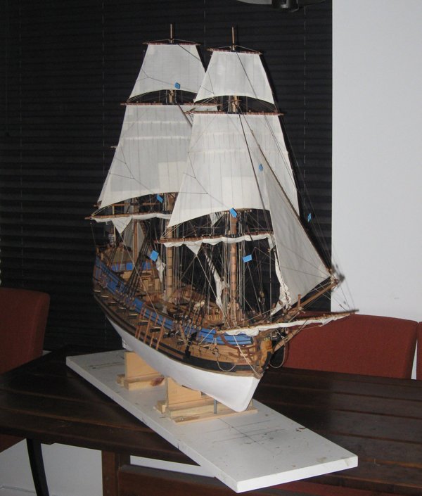
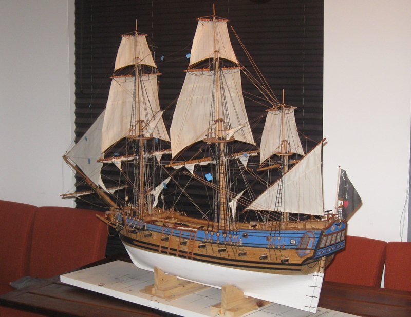
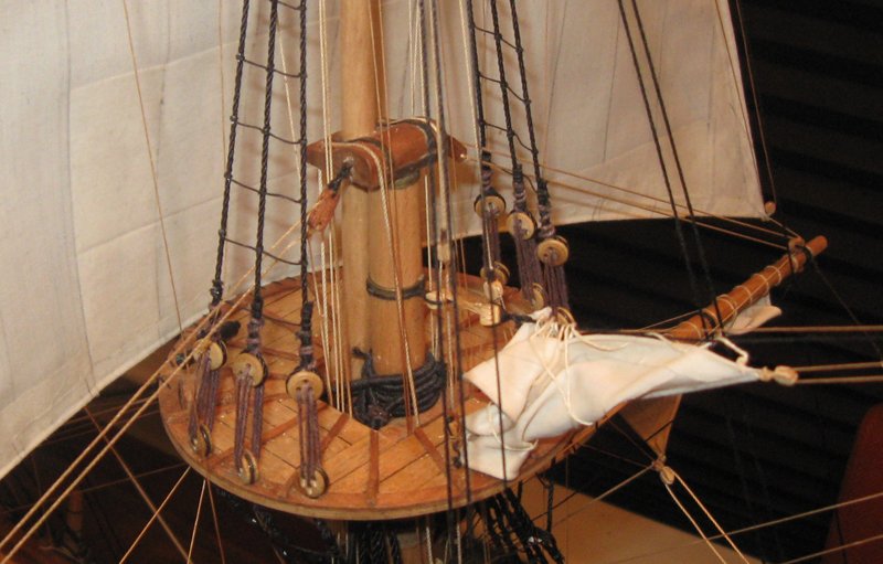
Hi all - Thanks for the likes and compliments. I am quite happy with how it finally came out, and the museum people seem to like it too. I did work out one final technique for the sails. Over the months that it took to make, hang, and rig the sails, they developed some kinks, bumps and dents that took away from the simple billowed shapes that I wanted. But I realized that they are all stiffened with matte medium, which responds to heat by softening. So I 'borrowed' my wife's hair dryer which has separate controls for temperature and fan power. Using the high fan with heat I softened each sail while blowing it forward (or to port for the staysail and lateen). The heat worked a treat in smoothing out wrinkles and bumps, and the fan filled the sail with wind. Once it took on the shape that I wanted I turned the dryer to its cool setting, but left the fan on high. After a few minutes the matte medium set in the desired configuration and the fan was shut off. None of the lines were damaged and the look of the sails was much improved. This should work with almost all stiffened sails, even those done with dilute white glue. Hope it works for you. Dan
- 241 replies
-
- 4
-
-
- queen annes revenge
- pirate
- (and 2 more)
-
Hi John - An interesting project, especially if you are looking for a level of historic appearance. Count me in. As for the color, I think you are right - in the photo it looks too far to the orange end of the chart. Since the color red was associated with the notion of being 'sacred', I imagine that it was derived from the color of blood. Somewhere between the crimson of fresh spilled and the brown/maroon of dried blood. A quick review of waka images on Google has canoes painted a surprisingly wide range of colors and tones. Some to the orange side, but some even to the purple end of the spectrum. This is compounded by photo conditions that can change the appearance of the same object. You could find a shade that you like and mix your current color with a bit of brown, black, or even dark green. Just record what you have added so you can duplicate it when you find the mix that dries to the color you want. Best of success. Dan
-
Hi to all who are following along - Sorry that I have not posted any progress recently, but I had to complete the second edition of the Queen Anne's Revenge for the North Carolina Maritime Museum. You can see the finished model by clicking on the Queen Anne's Revenge site below in my signature and going to the end. I will get back to this project shortly. Best wishes to all our friends in Texas and Florida. Dan
- 287 replies
-
- 7
-
-
- michelangelo
- ocean liner
- (and 1 more)
-
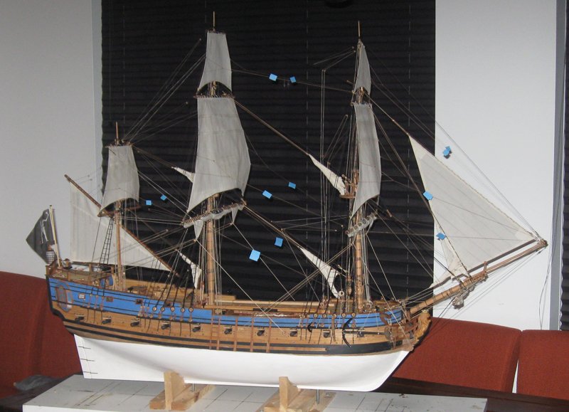
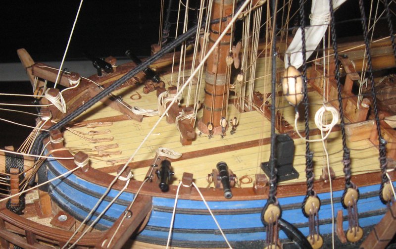
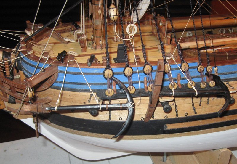
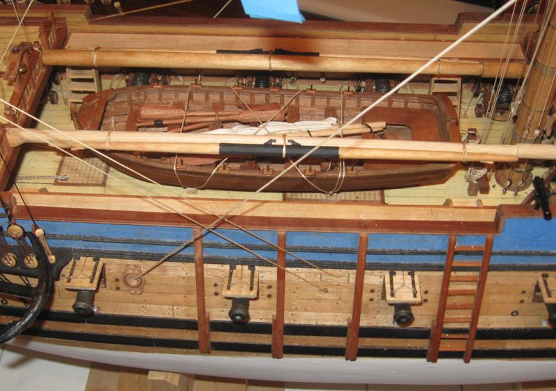
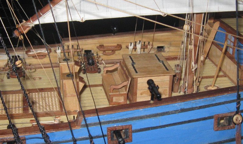
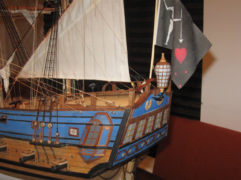
Hi all - Well, the second coming of the Queen Anne's Revenge is done - finally - and will be on its way to North Carolina on Friday. There are some minor differences between this one and the first (i.e. chains for the lower deadeyes rather than straps were discovered underwater, so they were changed on the model). But overall, they are very similar in both technique and final appearance. I did plank the entire lower hull before putting on the white stuff, which eliminated the earlier hairline cracks from the movement in the wood of the framing, but very little else. Here are some of the finished photos. The blue flags are Post-It paper to warn of where the bowlines for the sails are. They are well nigh invisible without them. All questions, comments and critiques are welcome. Be well Dan
- 241 replies
-
- 26
-
-
- queen annes revenge
- pirate
- (and 2 more)
-
I trust that there is an open chair in the front row. I have always been interested in ship types that are not the usual British, American and European line of battle ships. This should be a very fascinating build. The lateen rig is one that I know very little about. Looking forward with great anticipation to learning new things and watching your talented construction techniques. Dan
- 692 replies
-
- 5
-
-
- eagle of algier
- chebec
- (and 2 more)
-
Hi Nils - Just saw that you are thinking of building a Chebec for your next project. If memory serves, Frederick af Chapman has a wonderful plate of drawings in Architectura Navalis Mercatoria on the Chebec. Probably where Amati derived theirs, but I would trust a marine architect like Chapman before I would trust a kit maker to be accurate. I am sure that they did their best, but they probably made some changes to accommodate the limitations of kit manufacturing. You could get both, compare them, then decide for yourself. I will pull up a chair for a ringside seat whenever you start. Be well, Dan
- 2,625 replies
-
- 6
-
-
- kaiser wilhelm der grosse
- passenger steamer
- (and 1 more)
-
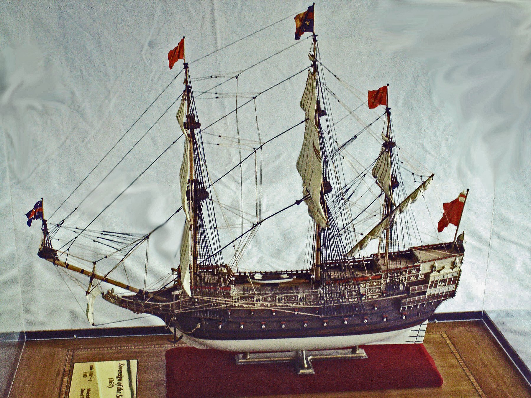
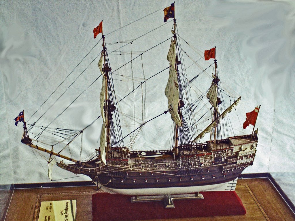
Hi Marc - I used a very similar technique when I did the Heller Sovereign of the Seas. First a primer, then a base coat of buff yellow flat acrylic. The difference is that I then used a wash of brown wood stain rather than a full opaque layer of brown paint which has to be partially removed. The issue I found with an opaque coat is that it is difficult to remove equally, especially around protrusions. Thus you get dark patches, like the lines across the stern of the Hollandia. You may have similar problems with the bolt heads on your wales. I completely agree with Herbert that you should do a lot of testing before committing to the final model. I know that your artistic talents are up to the job. Dan
- 2,696 replies
-
- 4
-
-
- heller
- soleil royal
- (and 9 more)
-
Superb, Nils. A museum in your home. How wonderful and inspiring. Dan
- 2,625 replies
-
- 7
-
-
- kaiser wilhelm der grosse
- passenger steamer
- (and 1 more)
-
Hi again - When you get the second kit, it will give you lots of test pieces to work out solutions to issues like the grain. As to that, I am sure that you have already worked out how you are going to simulate wood on the plastic surface. Once you have that base layer on which should fill the grain a bit, you might consider a 'filter' wash of very dilute darker color. It should settle into grooves of the grain to make them visible without overemphasizing them. Just a technique that I read in FineScale Modeler. Looking forward to seeing how you work it out. Puzzle problems like this are the best part of ship modeling for me. Dan
- 2,696 replies
-
- 3
-
-
- heller
- soleil royal
- (and 9 more)
-
Hi Marc - You are welcome to store stuff in my locker in the basement of my building. Not really convenient, since you are in Manhattan, but better than PA Dan
- 2,696 replies
-
- 2
-
-
- heller
- soleil royal
- (and 9 more)
-
Hi Chuck - Looking forward to watching your artistic and engineering talents on display once again. If those stem pieces fit together as well as you describe, you have taken laser cutting and kit making to the next level. Thank you. Dan
- 1,784 replies
-
- 11
-
-
- winchelsea
- Syren Ship Model Company
- (and 1 more)
-
Hi Ken - I'm always interested in an unusual build, and this promises to be a good one. Add me to the audience. 1:376 is an odd scale, but, if you haven't already, you can find 1:350 scale railings, ladders, doors, etc. which should work for you. Try Gold Medal Models and Tom's Modelworks. Are you building it hollow because you will be detailing the interior spaces, or because it will be R/C powered? Best of success with the project Dan
-
Hi Marc - Very nice work on the bolts. Looking forward to seeing how the hull halves will join up. Dan
- 2,696 replies
-
- 2
-
-
- heller
- soleil royal
- (and 9 more)
-
Dick - I see what you mean. It makes more sense than having the sail chafe against the mainstay. I am no sailor, and did not realize that spinnaker type sails billow so far upward. Thanks for adding to my knowledge. Looking forward to the completion of this lovely work. Dan
-
Hi Bill, Marc - I think you are talking apples and oranges. Bill is right that when a structural member, like a rib, frame or beam, is fastened with a scarf joint to the next structural member the fasteners go across the joint and hold the scarf together. But for the skin of the ship, the planks and wales, the fasteners go as Marc has shown them, around the joint so they hold the skin to the structural members beneath. Different purpose, different direction. Dan
- 2,696 replies
-
- 3
-
-
- heller
- soleil royal
- (and 9 more)
-
Hi Dick - I am thoroughly enjoying your build and especially your solution to the problem of the billowed mainsail and bonnets. I think you have done about as well as possible in the scale that you are using. However, I think you may have mounted it a bit too low. Using the colored illustration that you provided, doesn't it seem that the vertical trench in the mainsail is caused by it billowing against the mainstay? This is what I have seen in other illustrations. You could lift the yard up the mast until you get this configuration, which would also give the bonnets more room. Or I could be completely off base on this . . . LOL Whatever you decide, it is a beautiful model. Dan
-
Hi Marc - Lookin' good. I like how you are scribing the scarf joints in the wales. Seems to be coming out perfectly. One suggestion, which might speed up the bolting process a bit - drill shallow holes with an 0.022" bit, dip the end of your 0.020" rod into some glue and insert into the hole, clip close with cuticle nippers. No need to cut such small discs off the rod and try to apply them individually. Also, for the treenails, they would have been flush with the surface of the plans. So don't drill or melt holes. After you have painted the planks take a mechanical pencil or micro-tip pen and draw in the treenails. Much easier than holes, and easier to correct if you misplace one. Finally, an offer. I am upgrading my digital camera. The old one still works well, and you are welcome to it if you want. Just let me know, or I will give it to one of my grandchildren. Dan
- 2,696 replies
-
- 3
-
-
- heller
- soleil royal
- (and 9 more)
-
Hi Nils - Beautiful, beautiful work. I love how the figures bring life and action to the model. Congratulations. It has been a privelege to follow along these last two years. Thank you. Dan
- 2,625 replies
-
- 5
-
-
- kaiser wilhelm der grosse
- passenger steamer
- (and 1 more)
-
I'm having similar issues with my computer. Others in the family are also. Is this a concerted effort to disrupt the internet by Russian oligarchs? Arab terrorists? Space aliens? Or is it just the people who market those thumb drives that are supposed to fix the problem? Welcome to the Brave, but Confused New World. LOL
- 2,696 replies
-
- 3
-
-
- heller
- soleil royal
- (and 9 more)
-
Hi Marc - Here is another illustration of what I think happened to the Berain drawing of the quarter gallery - and how it most probably was originally drawn from an angle off the starboard stern. This first is a photo posted elsewhere on MSW of an excellent build of HMS Sussex. You can see how the aftmost gunports are situated just in front of the QG, but they are complete. While here is a view of the same model from a slight angle on the stern. Notice how closely it matches the Berain drawing with the two ports occluded. I think this optical issue has to be taken into account by anyone who wants to draft a plan that is closer to the working ship. Have a great summer. Dan
- 2,696 replies
-
- 6
-
-
- heller
- soleil royal
- (and 9 more)
-
HMS SUSSEX 1693 by 8sillones
shipmodel replied to 8sillones's topic in - Build logs for subjects built 1501 - 1750
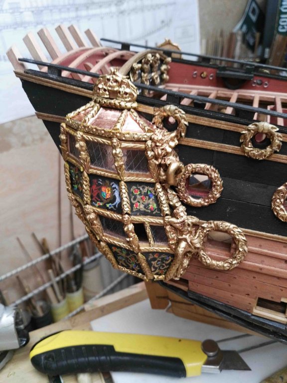
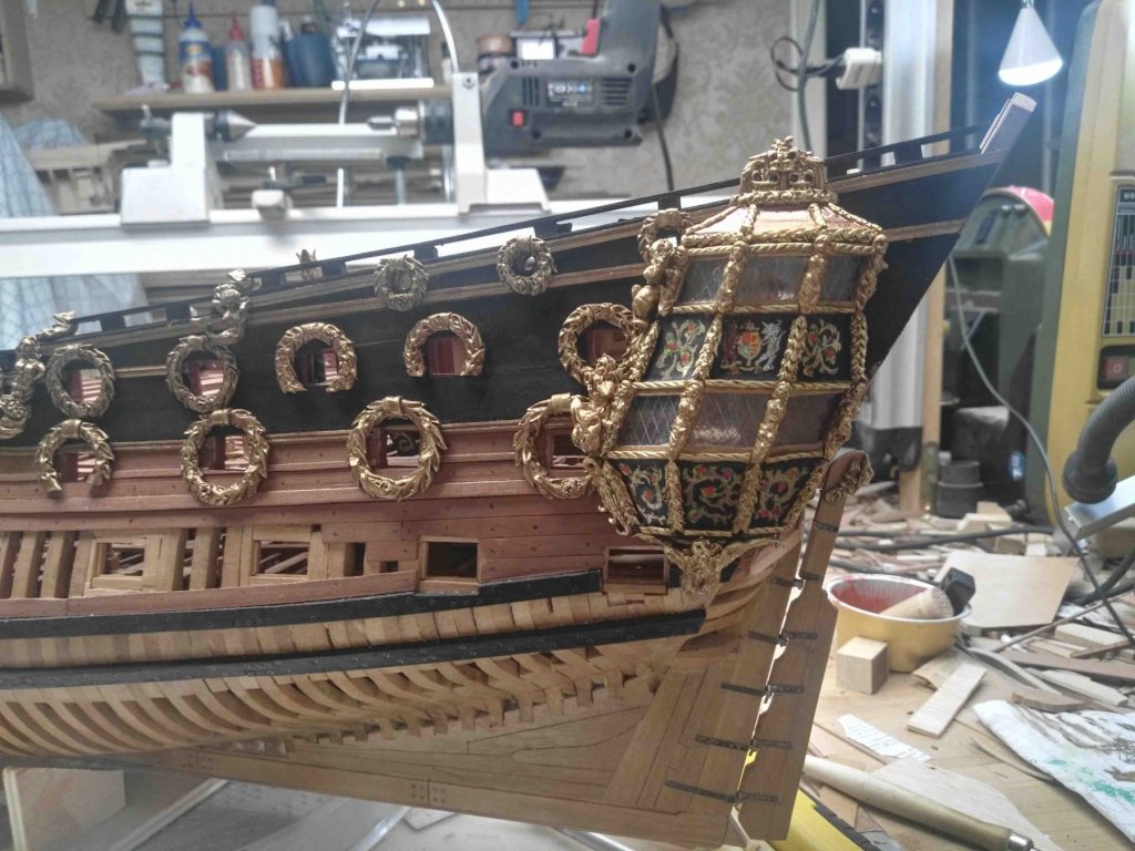
Hi John - Truly magnificent carvings and interior framing. I am enjoying reading your build log very much. I agree with Druxey and Jan that the carvings should be set back against the hull. Other decorative moldings can be cut around the wreaths, but the wales and other structural members should not be cut. The wreaths should have channels cut into their backs so they set back against the hull. The only other thing that catches my eye are the deck beams of the poop deck. I think they may have too much camber (round up). They look much more arched than I see in Dr. McCardle's book. Hopefully they can be carefully removed and replaced. Otherwise, just wonderful work. Dan -
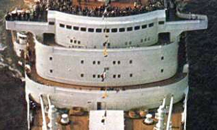
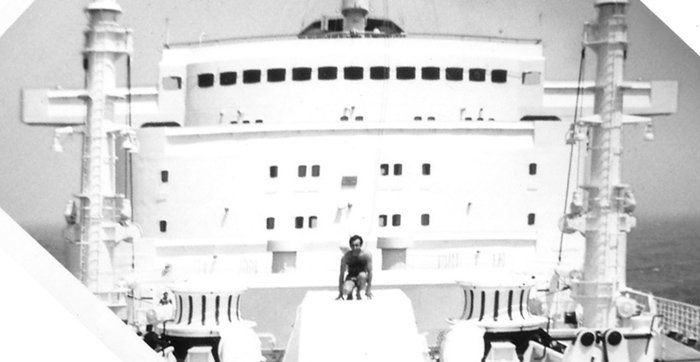
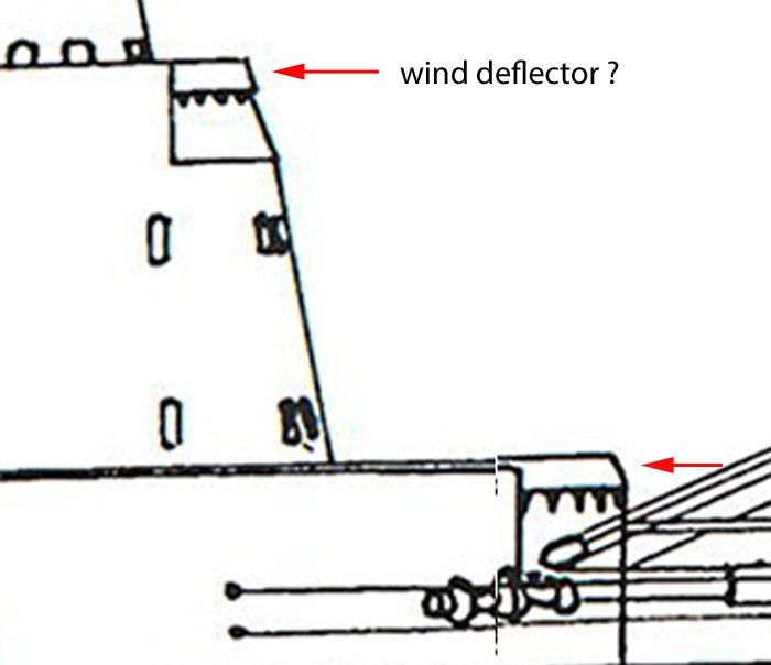
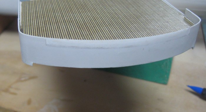
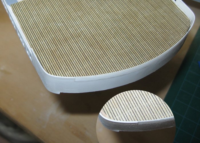
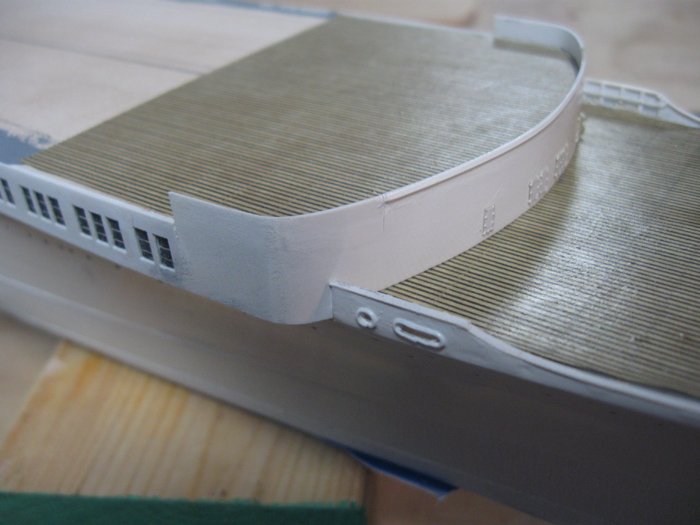
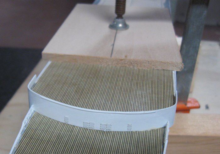
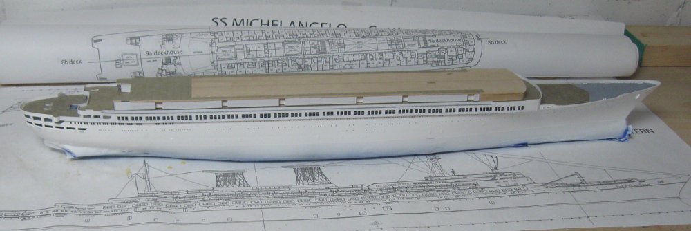
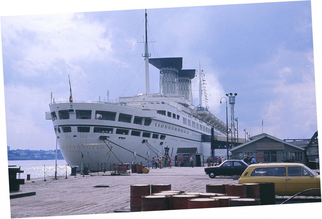
Hi again. A short segment this time. More when I have the time to write things down. Before moving up to the Boat deck, the forward end of the Promenade deck had to be detailed and the deck secured down to the lower hull. In this photo the deck is the lowest of the three layers of the forward superstructure. There are some doors, one of which is open, and some supports for the cargo booms, which will be added later. The interesting feature is the upper edge of the bulwark railing. This feature can be seen across the top of the railings on the upper superstructure and on both bridge wings (ignore the man kneeling on the bow companionway - I have no idea why he is there). From the side it is clear that these must be wind deflectors, a detail that was explained by Andy (realworkingsailor) during the Andrea Doria build. Unfortunately, his photo of the feature has disappeared from my log. He described them as “a concave (when viewed from fwd) shaped piece of steel attached by brackets about 3" ahead of the bulwark.” On the Michelangelo they appear to be flat, not concave, but angled back to direct the wind. This matches the feature as best as can be derived from the plans. Note that the bulwark is shown to be cut back to give the deflector some space. With all that in mind, an area was marked out on the front of the Promenade deck railing and shallow cuts were made at each end. The top edge was reduced in thickness from 0.02” to less than 0.010”, as seen in the insert. The rest of the angled area was sanded to this edge. A piece of styrene strip 0.010” x 0.040” was cut to length and installed at an angle along the top edge of the railing. The shadow line that this created looks very much like what is seen in the photos, so I was happy with the result. Six photoetched outer doors were painted and installed, then the Promenade deck layer was glued and set in place. The first of several pipe clamps can be seen doing its job, with wooden pads protecting the model surface both top and bottom. So here is the model with the Promenade deck finished and installed and the Boat deck set in place to judge the various sizes and relationships. More soon. Be well Dan

- 287 replies
-
- 10
-
-
- michelangelo
- ocean liner
- (and 1 more)
-
Hi Marc - I found a photo that shows the kind of doors that I think we are discussing. It is of similar ones at the stern, but you get the idea. Unfortunately, any doors along the side cannot be seen due to the angle of the photo. What do you think? Dan
- 287 replies
-
- 4
-
-
- michelangelo
- ocean liner
- (and 1 more)