
.jpg.d84ec4dad1d7791e855dca06210ab6f3.jpg.40b7a0ea2cc62bf0a3ec2a716005383a.jpg)
hollowneck
-
Posts
1,511 -
Joined
-
Last visited
Content Type
Profiles
Forums
Gallery
Events
Posts posted by hollowneck
-
-
2 hours ago, Blue Ensign said:
I think that just about sums it up James,👍
Yep.
7 hours ago, paul carruthers said:compare to golf club membership etc
...or a "Wine Club" subscription🥴
The Indy will not be inexpensive, but as we all know, Chris' new kits will give you an excellent return on your investment.
- AJohnson, Canute, thibaultron and 4 others
-
 7
7
-
2 hours ago, Blue Ensign said:
Having received a gypsy’s warning from Ron (Hollowneck) about possible issues with the level of the rail and fit of the Hammock cranes, I looked again hard at this area.
Good problem solving B.E. A little camber to the cap rails is O.K. Mine aren't perfectly level but must less awkward looking after I "tweaked" the bulwarks and supports. The hammock cranes , once rigged with their rope lines are easier to keep aligned. No glue in the openings, just the tension of the thin rope keeps them in-place.
- chris watton, mtaylor, Blue Ensign and 1 other
-
4
-
On 5/5/2022 at 9:34 AM, Blue Ensign said:
On my build I found no reason to trim the gangboards on their outer edge as indicated in the blurb.
Ditto, I found this suggestion to trim the gangway patterns in the instructions very curious and not necessary. Your improved steps for the gangway look excellent. Good researching on the McKay/Amazon information and coming up with a clever solution.
I've noted a similar quirk in your waist capping rails to my wrestling with this area of my build: both caps lean outboard and by different angles. In dry fitting I was able to reduce some of this unfortunate disparity by carefully trimming the bulwarks - which process did result in having to remount several of the supports. When you proceed to mount the hammock cranes this "tilt" to the cap rails will be quite apparent. I improved this issue in my build, and you surely can too!
- mtaylor, Dave_E and Blue Ensign
-
3
-
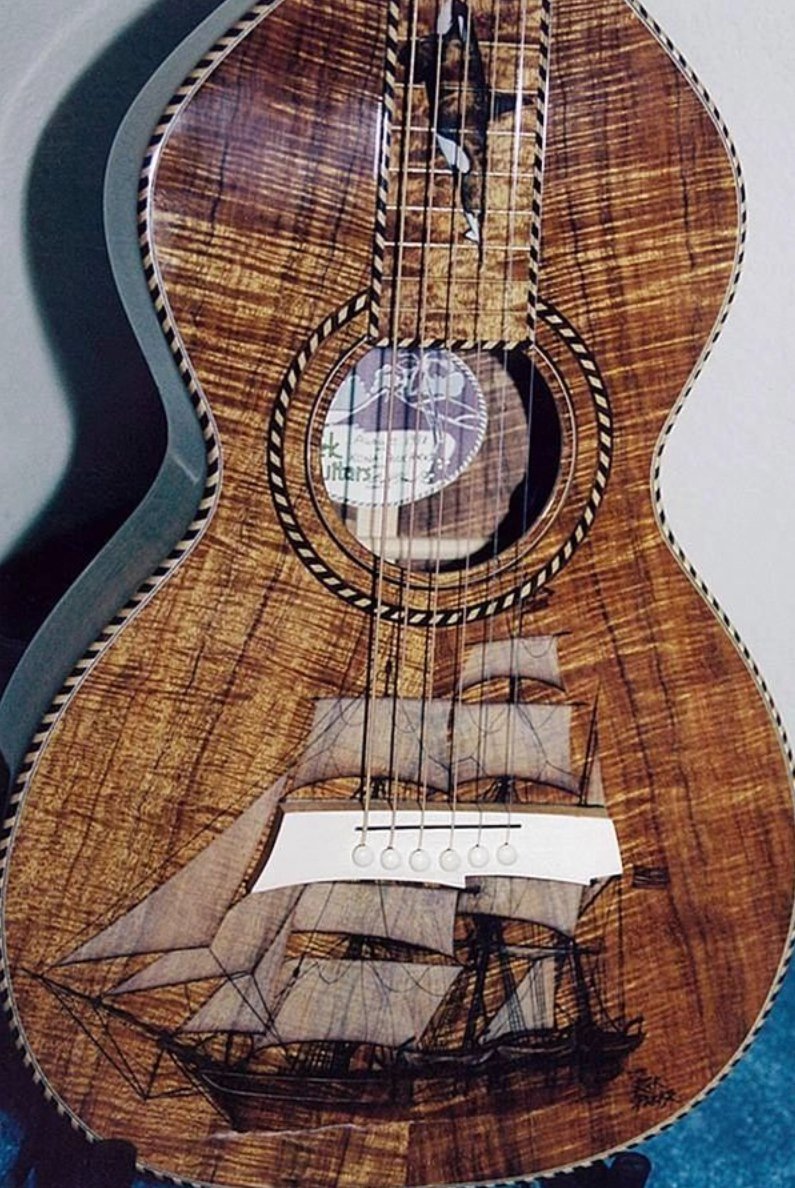
14 hours ago, BobG said:
many hours of playing guitar has all but shut down my shipyard lately.
Mui sympatico here, Bob. There are Ship models and then there are other pursuits...
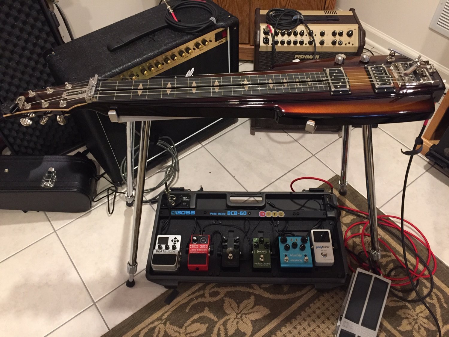
How about combining the Best of Both Worlds?...(first pic of a Weissenborn acoustic lap) or
Cranking the Spinal Tap Dial up to eleven on the Marshall?


-
3 hours ago, chris watton said:
All my kits are 64th.
Cannot tell you final length and height, as I am yet to draw the masts and bowsprit. It will be around Agamemnon size, taking around 30mm off the height, but add about 120mm to overall length, as I shall do Indy with a Flying Jibboom
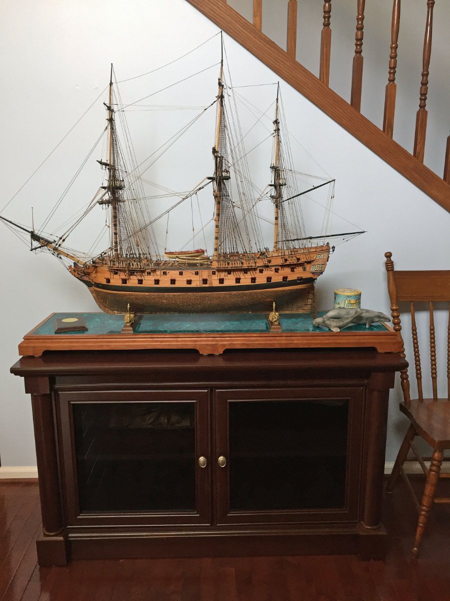
Yikes. I'll need to find a new spot for my 1/64 HMS Ardent from Chris (Caldercraft Agamemnon)...A fully-rigged 64 looks like this in my home's hallway entrance. I'll also need to consult with my Wealth Management Investment advisors.😂

- thibaultron, mtaylor, Gord-Canada and 9 others
-
12
-
On 5/5/2022 at 12:24 PM, chris watton said:
Tomorrow I shall start on the various cleats for the bulwarks and decks, and then move onto the bow area.
Chris, how 'bout rails - especially ekeing - in a 3D print?
3 hours ago, chris watton said:I develop how I would want my own kit to be, and then work out the price.
Impressive, über-detailed model. Impressive über moolah. Cheers. What will be, will be.
- mtaylor, Canute and thibaultron
-
3
-
12 hours ago, Blue Ensign said:
Hello Ron,
Rather than clutter up your log if you care to look at my Pegasus log (link below) and go to Page 6 Post #171 covering the Main stay, there are full details with photos of how I made the mouses.
There are also details on my Cutter Alert log page 8 post #223
Hope this helps.
Regards,
B.E.
Hello B.E.- many thanks for taking time to identify some info from your past Build Logs. I'll visit both. Much appreciated.
Now - off to build a better Mouse (trap)!
- chris watton and mtaylor
-
2
-
11 hours ago, Blue Ensign said:
She's looking impressive Ron, and those crowsfeet are a great improvement. I do agree with Druxey those mouses could use a little fettlin'. I make mine out of styrene tubing covered with netting from ladies tights which gives the woven look.
Thank you, B.E. My "mice" can be improved, and this isn't difficult to re-do. However, will you please give me a pointer - or two - on how to fashion the tapered styrene tubing so that it becomes conically-shaped. I've used dowel, drilled thro' and tapered with sanding to fashion better looking "mouses" for previous models, so indeed I can do better. I'm curious if your tubing method will yield a better result and be easier to make?
Your layering of "ladies hosiery" looks very effective from what I can see; I have several daughters (and granddaughters) who can help me out with this supply chain!
However, as you've suggested, re-rigging my stays to pass over my shrouds is too far to go at this stage.
Camilla's ship's boat will indeed be a yawl, the 24', 3D printed resin one I purchased from Vanguard. I'll follow the kit's instructions (mostly) on the various pieces needed to outfit the resin boat.
- mtaylor and chris watton
-
2
-
54 minutes ago, druxey said:
Now, those are crowsfeet! Well done. At the risk of being a pain, can you shape them mouses a little more mouse-like?
(Hint: stays go over the shrouds. See photo.)
Thanks, druxey.
Now that I've properly dealt with a talkative avian (two more circling about), another pest crawls out of my woodwork: mice.
Where there's one, there's more!
Hmmmm...let me think about this. No Pain. No Gain?
- Ryland Craze, druxey and mtaylor
-
3
-
Back at it following the Annual Joint Clubs Northeast Ship Model Conference in New London, CT. Great models to see. Good attendance on a beautiful day at the beachfront venue.
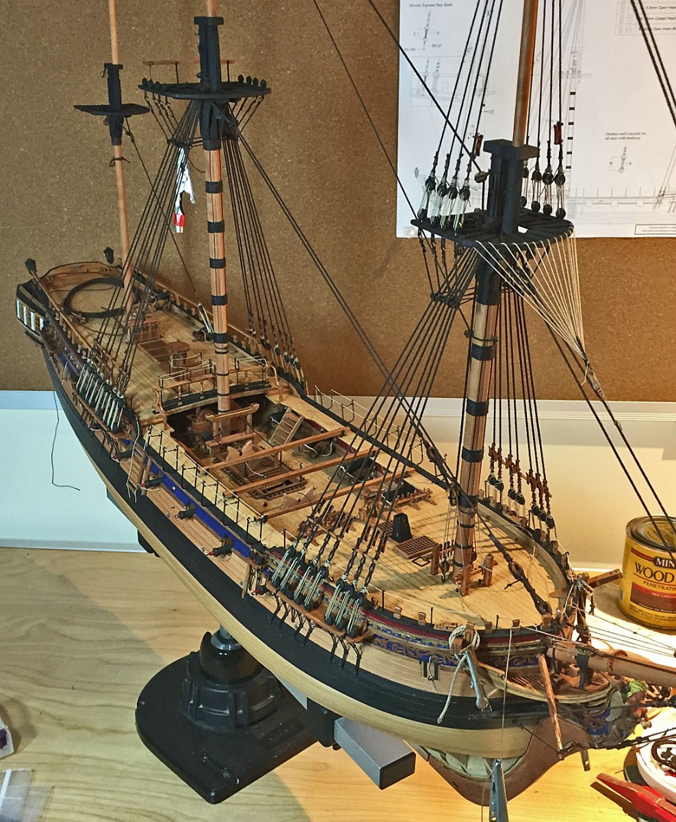
Here is an update I made on HMS Camilla just before I hit the road to New London.
A better result with thinner rope for the crowsfeet - and a redux on the "over-under" threading required that avoids the doubling of the lines I'd previously rigged. I'm happy this has been straightened-out - thanks to B.E. & druxey who helped me to re-focus on my work. BTW: those small blocks that rig the euphroe block to the stay are 2.5mm pear singles.
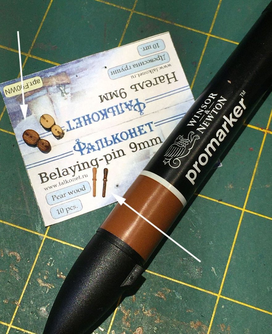
My promarker, alcohol-based coloring pens arrived and I immediately tried them out on some boxwood violin blocks and pear belaying pins. The color, raw sienna, is the darkest in the 5-piece "brown range" set I bought. I used both marker tips: the flat, wedged "sharpie" point and the "pencil tip" point. The belaying pins only needed one pass of the coloring whereas the blocks needed two to achieve a nice "chestnut-like" reddish sheen. Boxwood is a more tightly-grained hardwood than Swiss pear and therefore needs more than one color pass.
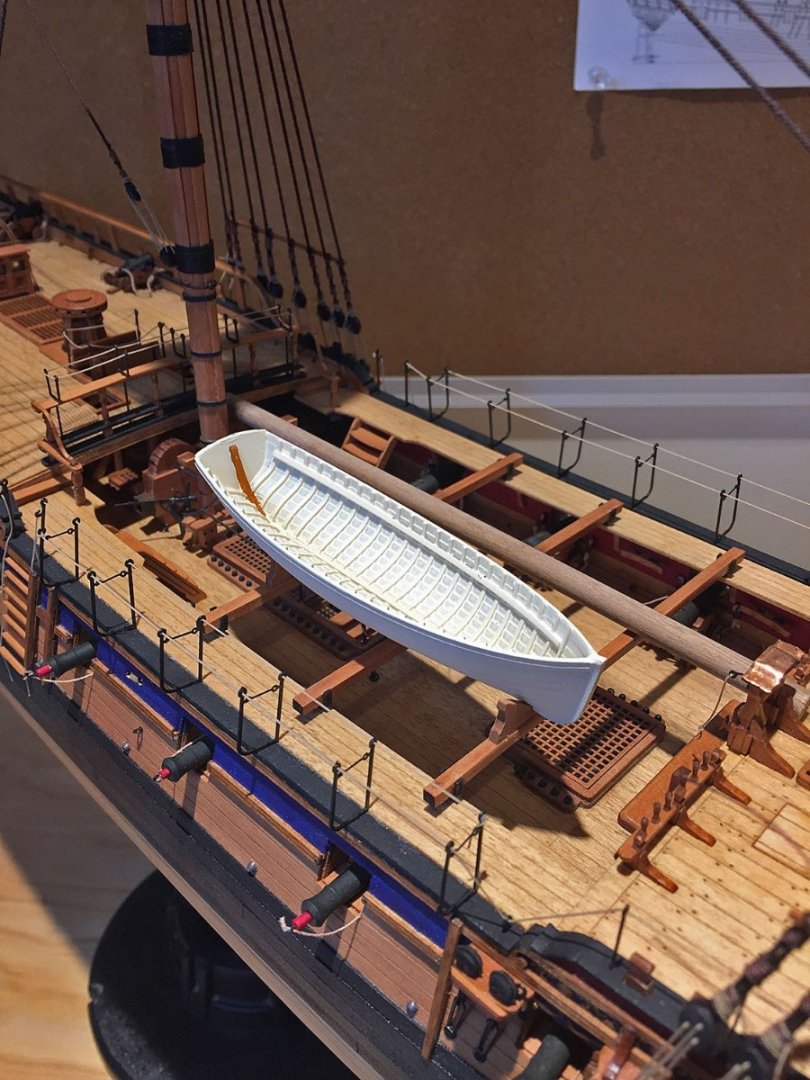
Taking a small break from rigging, I'm now testing some paint colors for the ship's 24' yawl. The clinker-styled boat is the one I purchased from Vanguard and not provided in the Sphinx kit. Here, the resin boat has been primer painted in Titanium white with two coats from the Liquitex pro series rattle can. Not easily seen in this photo is the off-white color of this paint which may suffice for the boat's finished hull exterior.
The thin brown line at the boat's transom is a test for color. This matches quite well with the pear wood pieces that will be added, namely the thwarts and aft seating. There are quite a few choices of internal boat components that are provided in the kit. Some of these will be brass P/E, the remainder in lasered pear.
I'm only building one boat for my model so I'll pick n' choose the components that will best fit this 3D resin print. The kit includes a full, three boat complement in pear and thus there is quite a large selection of very detailed bits n' pieces to make all the ship's boats quite convincing, right down to tiny oar locks and decorative boards. As this mini-project develops I'll post photos, of course.
Most builder's of this kit will opt to build all three pear boats provided and array them across her midships on the skids. I'm just not one of them.
At this writing I'm seriously considering airbrushing a custom color mix for the boat's interior before I add the P/E and laser etched pear details.
One other detail: the walnut dowel behind the boat lying across the beams is a 'test' piece for adding a spare topmast that's on my checklist. I'll make this piece when I get started on Camilla's yards since I'll be spending time on my Proxxon mini-lathe making them.
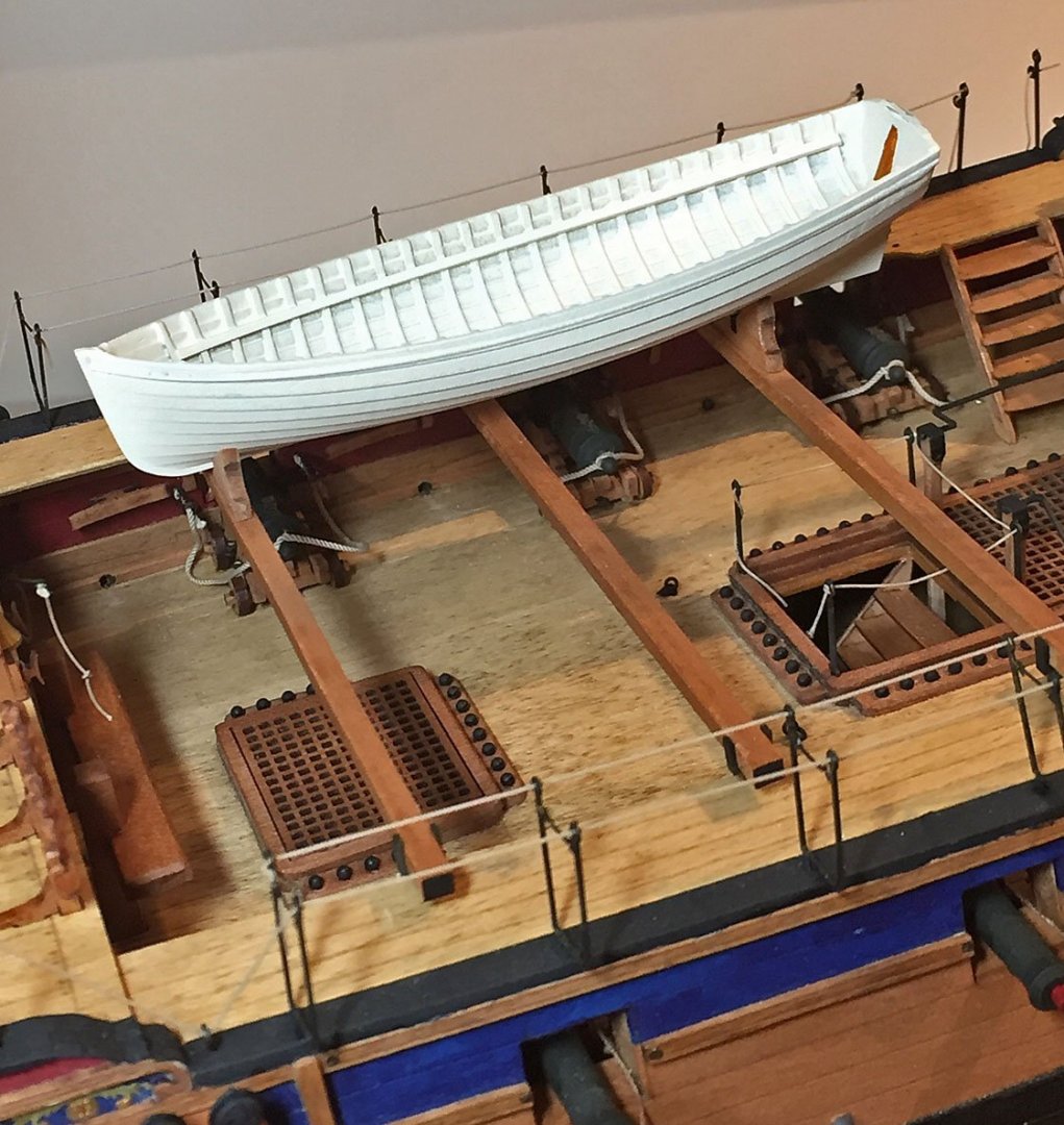
Another view of the boat, prime coat painted. This view better shows the nice clinker'd hull and the ribs. Once completed, I'll leave the boat in this upright position, strapped down across the skid beams.

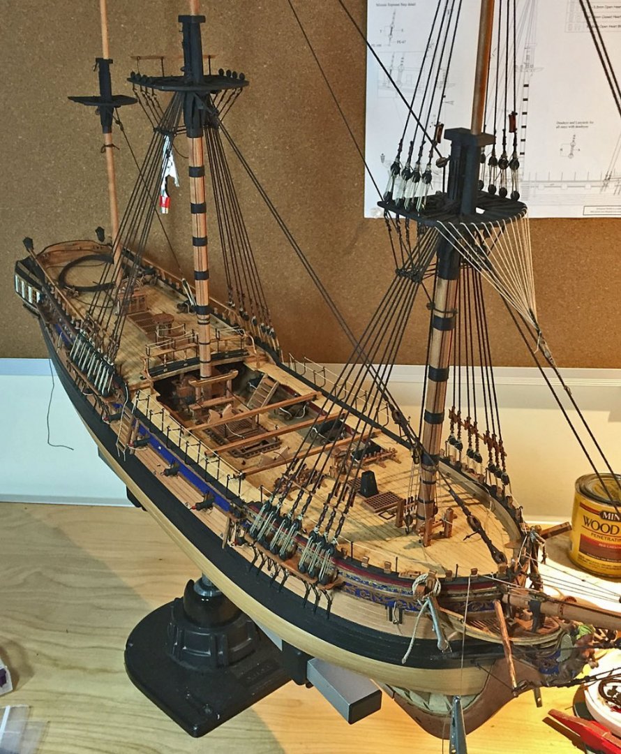
This photo shows two brass deadeye rigging jigs in position for shroud tying. The shroud line pair (main topmast) has been cut to length and seated around the tophead crosstrees and brought down to the top's deadeye and brass jigs. Once wrapped around one brass leg (on the right side) to hold the shroud line in-place, I've left a small length to wrap a deadeye and it's subsequent lashing. The grey-tipped alligator holds the shroud securely in position as the opposite end of the line is wrapped around the deadeye's channel (on the left). After pulling the shroud line fairly taut, I lash the first of three lashings with the brown upholstery thread I use for nearly all my line lashings. Just the first tie-off is shown here. This lashing line will subsequently wrap 5 or 6 turns and then be tied-off.
The shroud line to the deadeye is also held in place by a second alligator clip to maintain tautness. Once the shroud's left deadeye is secured, the line around the right brass jig is wrapped around a second deadeye placed on the jig; once the spacing is evened-up, the shroud is secured with it's lashings.
This set of brass wire jigs have sharpened, tapered tips so they can easily slide into the miniscule holes in the 3 mm diameter deadeyes. For the larger deadeyes at the channels I use slightly thicker and lengthier brass jig sets of the same configuration that provide wider spacing between the deadeyes.
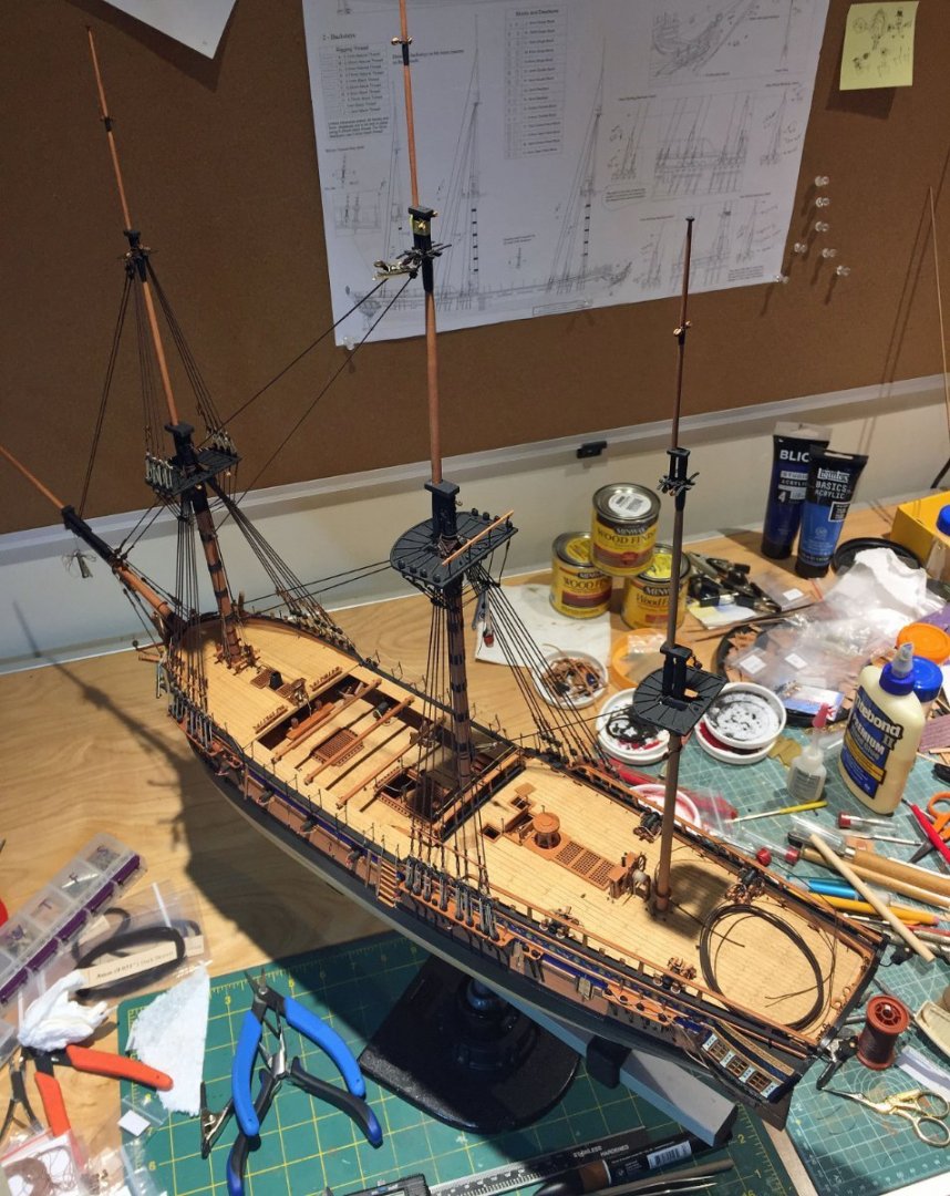
A gull's-eye view of progress on Camilla and my out-of-control work surface!
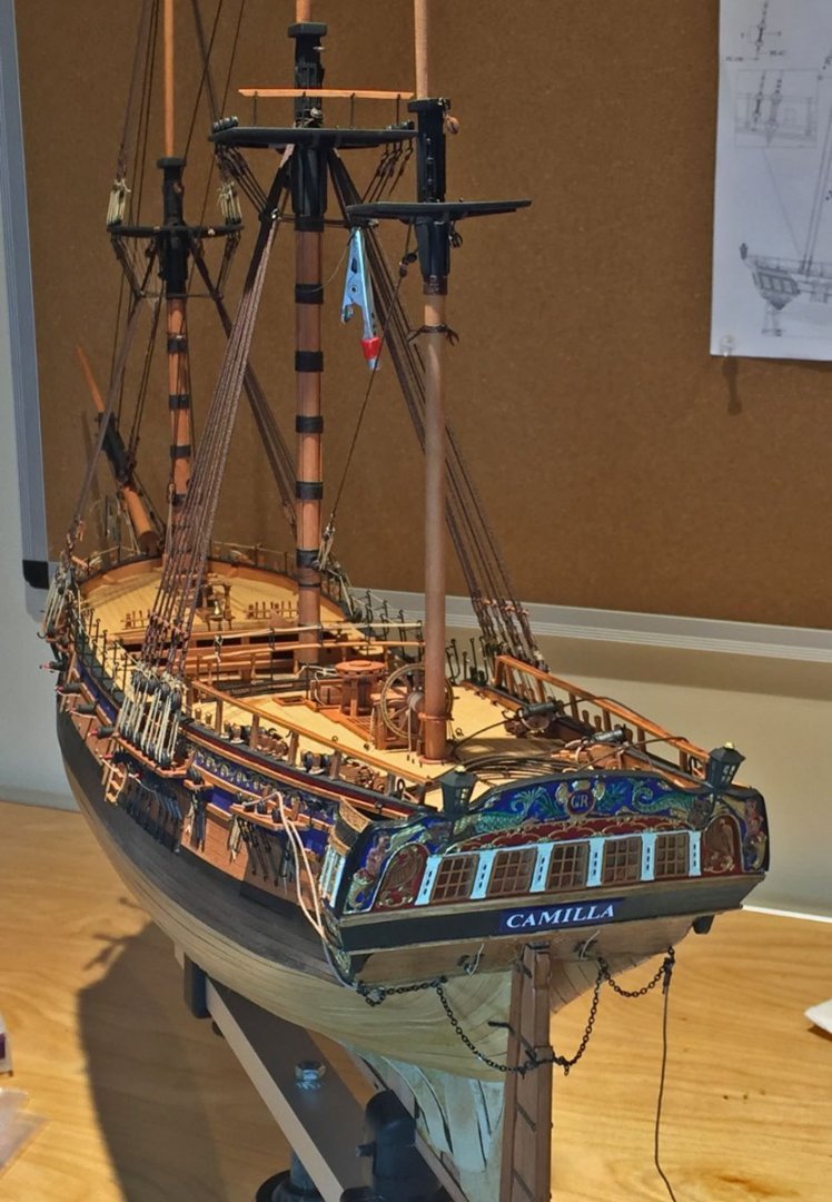
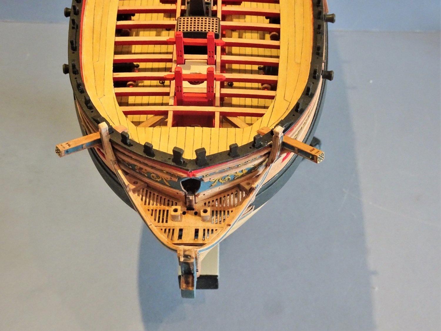
A view from the stem.
The mizzen shrouds await.
-
32 minutes ago, Blue Ensign said:
You’ve got it Ron, 👍 and 0.1mm line is about spot on for Crowsfeet, equates to 3/4” circ. line.
Thanks, B.E. Yeah, 0.10mm rope will be like what I envision its like for fly-tying fishing lures, as druxey has advised!
Mmmmm... smoked rainbow trout.
- mtaylor, Thukydides, druxey and 1 other
-
4
-
4 minutes ago, glbarlow said:
Here's an example of one of those clumsy efforts done 12 years ago on my Pegasus (and long before I knew of Syren rope) along with the now no longer made Warner blocks.
Thanks, Glenn. I confess I rigged my HMS Swan's (neé Pegasus) crowsfeet correctly. Why I didn't look closer at how I accomplished this years ago, is beyond me.
I used old-school Warner blocks too. They are still beautiful looking IMHO.
For kit building, there have been dramatic changes to the aftermarket for our hobby in just a few short years, accelerated by our MSW forum.
-
40 minutes ago, druxey said:
And yes, that it the right way to go about it. Use the thinnest line you can: I've used fine fly-tying brown line 6/0. usually crowsfeet look too clumsy on models.
Thanks druxey. I believe I have some .10 mm rope, hopefully enough to do all my tops!
I neglected to mention in this topic that I have yet another important, accurate reference for rigging...😬
- mtaylor, chris watton and druxey
-
3
-
8 hours ago, Blue Ensign said:
Your Crowsfeet look nice and taut Ron, but can you clarify if the method of reeving is one of your simplifications?
I don't think I recognise the double looping of the line through the rim top holes, effective, but not necessarily authentic as far as I know.
Regards,
B.E.
Indeed, my method is inaccurate, but not a simplification, per se; I used way too much rope and thus, this rigging reeving turned into a jury-rig. After consulting the following principal references I have for rigging, I'm up for ANOTHER re-do.
Good eye, B.E.: it doesn't quite look right to me either. Thank You.
Here's my solution, some background for thread readers:
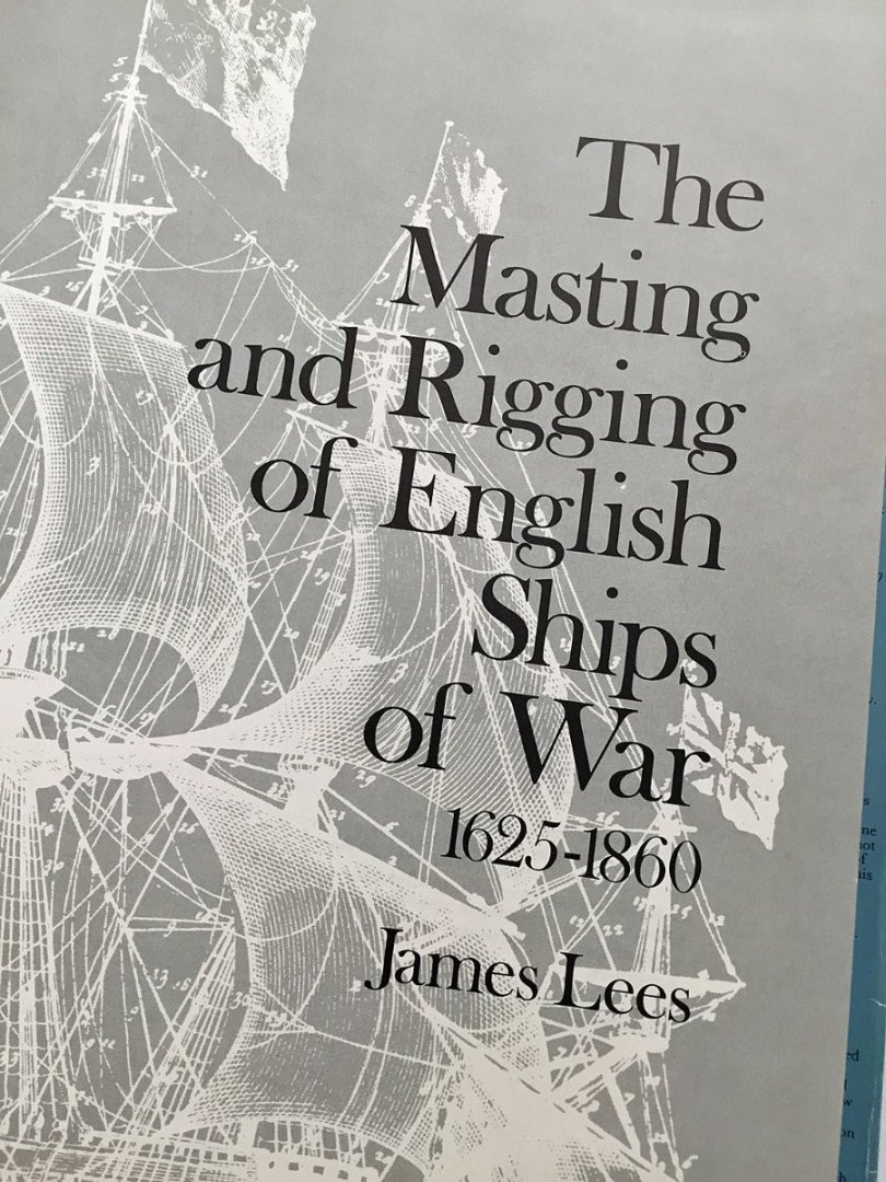
The standard reference for rigging, James Lees. The "Bible."
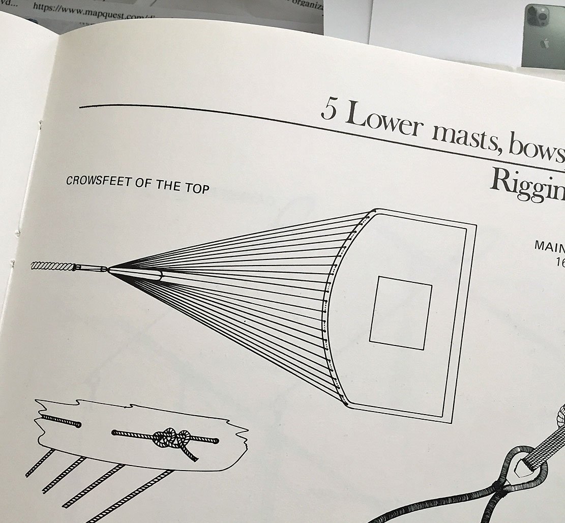
James Lees, Pgs 44-45. Rigging to the Foremast.
This is the only pictorial reference for crowsfeet rigging in the entire 212 page tome, which the text explains "...It [crowsfeet] ceased to be generally used by the end of the eighteenth century." The text does give a written explanation how to accomplish this artistry, but I found it confusing, even though I've done this rigging several times in my ship modeling life.
Basically, for the foremast, I invented my own, semi-accurate solution. The English have a saying for this: "that's not cricket!"....so...in the next photo, my Dear Watson, I'll show you the evidence for a more accurate solution to fixing (undoing) my unique (call it "creative") method for rigging!
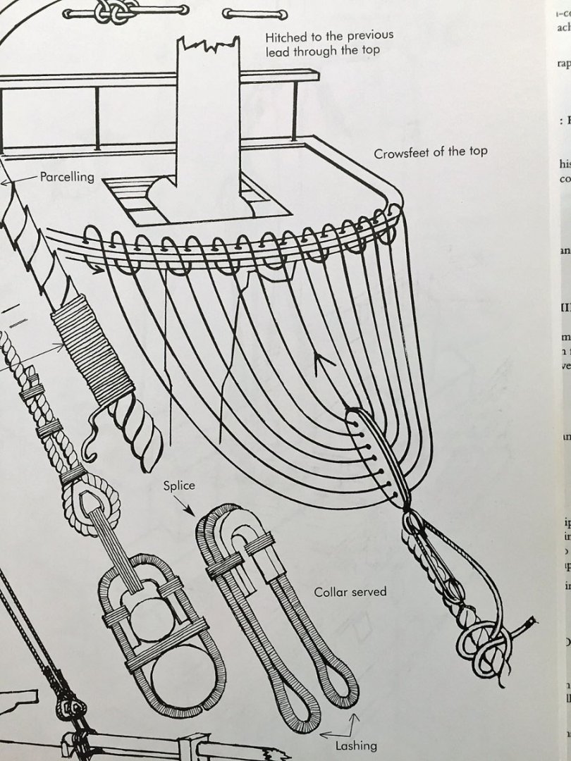
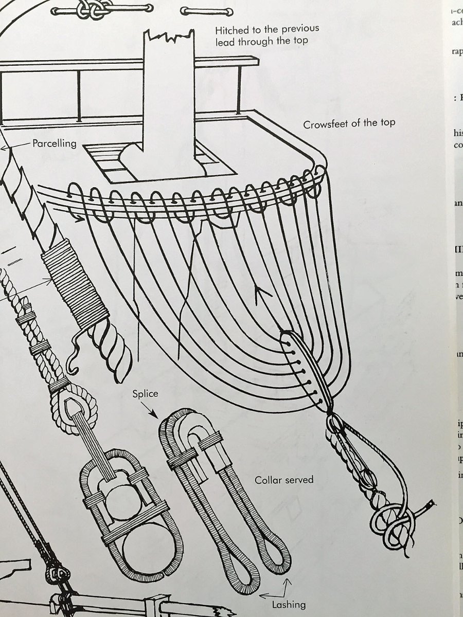
"Elementary, Mr. Neilson, Elementary." This photo from Lennarth Petersson's Rigging Period Ship Models book (page 15), is my "go-to" main visual reference for rigging, including its extensive information on sails, their configurations, rigging and excellent info on belaying.
You can see in Petersson a pretty clear depiction on how to go about accomplishing crowsfeet reeving. This procedure will apply to all three mast tops on my Camilla.
Why I ignored this clearly illustrated reference I can only chalk up to "a senior moment."
I'll fix my erroneous foremast crowsfeet rigging tonight, after an Eastern Conference NBA playoff game.
Thanks again, B.E. for the sharp eye and the gentle query into my rigging madness.
Where would I - we all - be without Model Ship World?!😳
- mtaylor, chris watton, druxey and 3 others
-
6
-
-
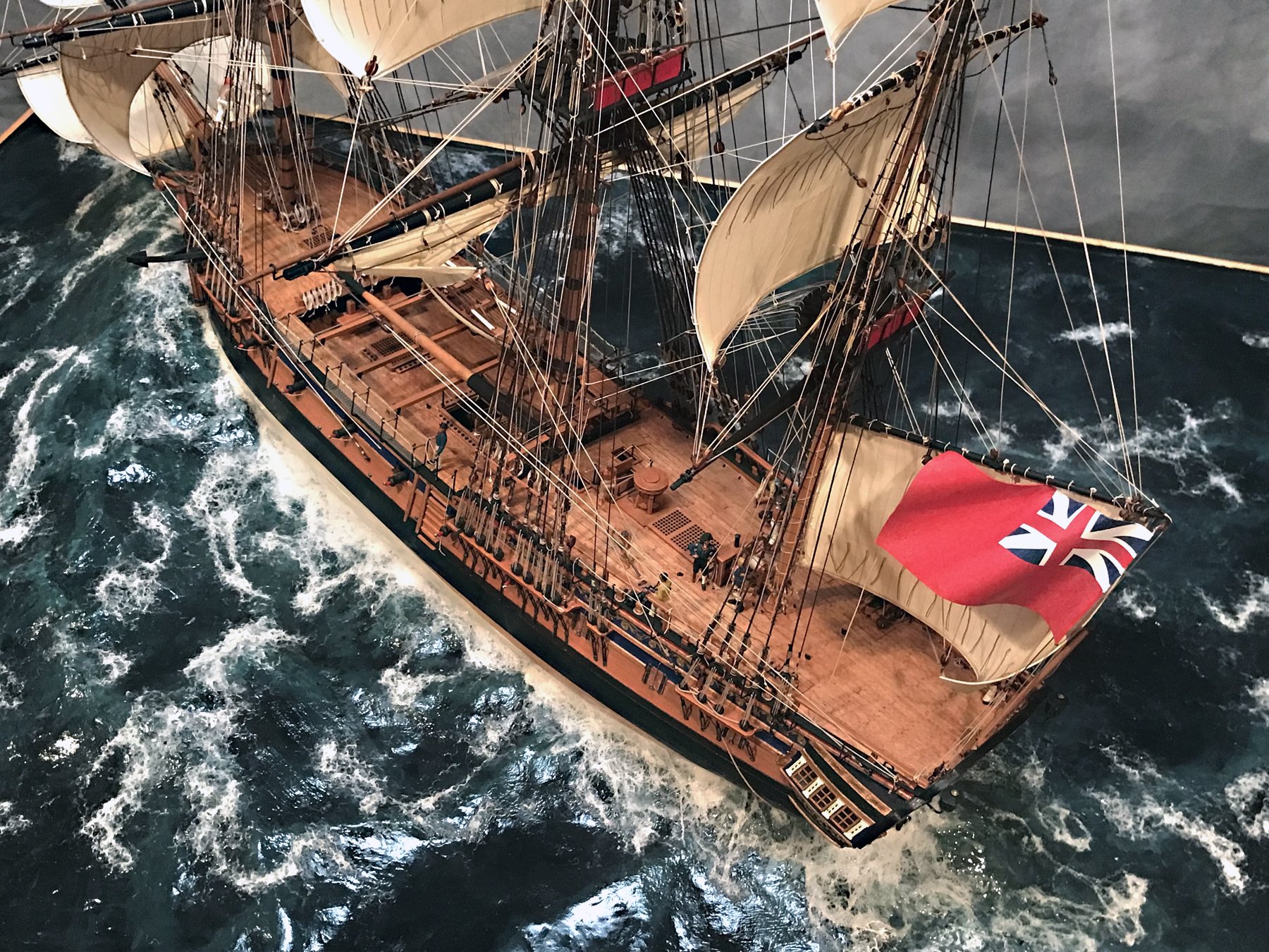
14 minutes ago, mtaylor said:
This is definitely the gold standard for this model.
Yep. A stunning model!
- Dave_E, Blue Ensign and mtaylor
-
2
-
 1
1
-
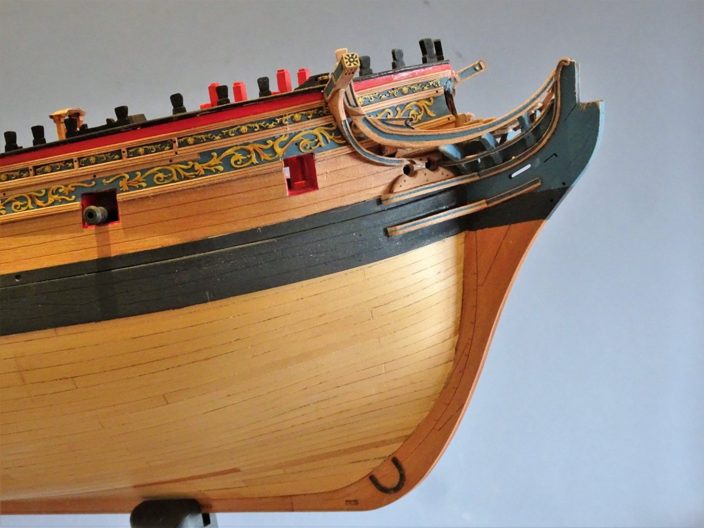
On 4/24/2022 at 2:35 AM, Blue Ensign said:
Thanks Ron, I just hope my blue colour mix lasts the distance. It should do there's not a lot of painting left to do.
I felt I had to put the extra effort into the Rails as there will be nothing to distract the eye, no Catfalls with large hook, anchors, or rigging.
Regards,
B.E.
Good point. I'll certainly have all the anchor bits n' buoys mounted, including the possibility of adding an anchor lining. I thought about this possible addition as I was rigging the deadeyes...I did add a centre-deck spanshackle, so the crutches make more sense. How do you plan to handle the masts? Stubs with broken wood? Angled tops? A fellow artist/builder would like to know! Cheers!
- Dave_E, Blue Ensign, mtaylor and 2 others
-
5
-
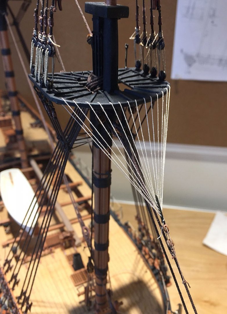
Rigged the crowsfeet to the foremast.

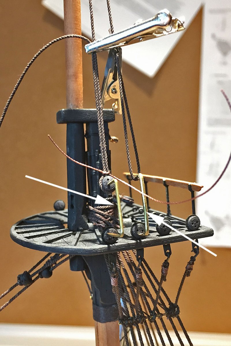
PLEASE IGNORE THIS PARTICULAR PHOTO'S INACCURATE ADVICE! (jump to the next thread in this log). BUT THE OTHER TWO PHOTOS BELOW ARE HELPFUL.
Rigging the crowsfeet can be tricky. Before running the continuous, laced line into the top and down to the euphroe block, I start with securing the euphroe tackle to the stay (see closeup and description of this below). After lashing the two blocks with their lines to the euphroe, I position both on the stay and temporarily clip them into place do they don't slide around when subsequently tensioning the lines from the euphroe to the top.
To determine how much line to allow for the crowsfeet, measure down to the eurphroe block from the edge of the top and multiply this length by the number of holes you'll feed the rope to the top. I add another 2 or 3 inches. In this example, I had a total rope length of approximately 42." There were twelve runs to the top. The distance from the euphroe lashing is about 8-10 feet from the stay to the edge of the top. This will be a long run of rope that can easily get fouled in other parts of your model. Proceed appropriately.
My crowsfeet line is "beige" (natural hemp color) line that is nominally .20mm dia. This is roughly equivalent to 1/2" diameter rope at full scale.
For reference, the main propose for the crowsfeet was to protect the foot of the topsail from becoming worn and fouled on the tops.
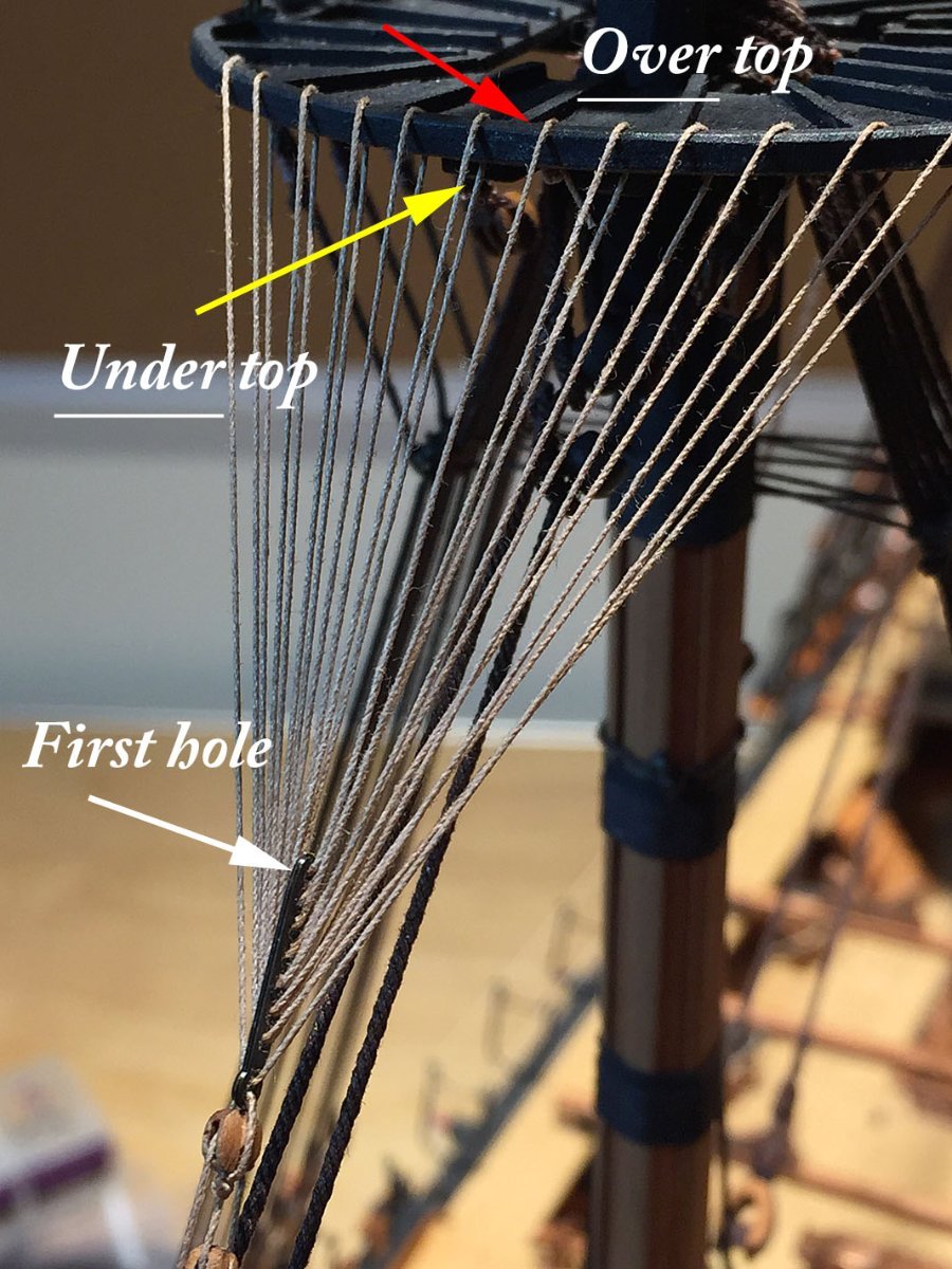
In the above photo, I've indicated the beginning sequence to this rigging, starting with the line entering the hole on the top at exactly the midpoint (in this case, the first hole to port, close to center), the Red arrow. Tie a stopper knot in the line after it is pulled through the top's hole so it stays secure for the balance of the rigging. You can trim this down after the full run is completed.
Next, run this line to and through the FIRST hole at the closest end of the euphroe block (white arrow). Now, run the line back up to the top to the first hole on the starboard side, UNDER and through it (the yellow arrow). The balance of this "lacing" is straightforward, running in sequence, alternating port-to-starboard and along the top, filling all the holes in the euphroe.
Once the line is fully rigged, you'll likely need to even-up the tension across this array of lines; I use my needle point tweezers to finesse this step. You want these lines to be taut but not so much that the mast stay is pulled upward from too much tension exerted by the euphroe tackle lines.
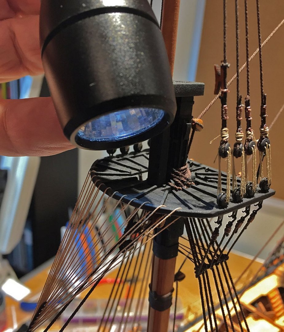
Here, I'm showing how I use a small flashlight to illuminate the tiny holes in the top from my hand position above it. The crowsfeet rigging progresses upward, under the top - trying to poke a .20mm diameter rope into the holes is an exercise in extreme patience, particularly when the top is painted black! The light shining downward helps immensely to see where the rope needs to enter upward through the tiny holes. I use my needlepoint tweezers for this task.
TIP: Don't try to rig crowsfeet without making the end of the rigging rope stiff with glue first - just a tiny amount ( I use CA) so you create a "needle" point on the end. You'll trim this glue-hardened end off later.

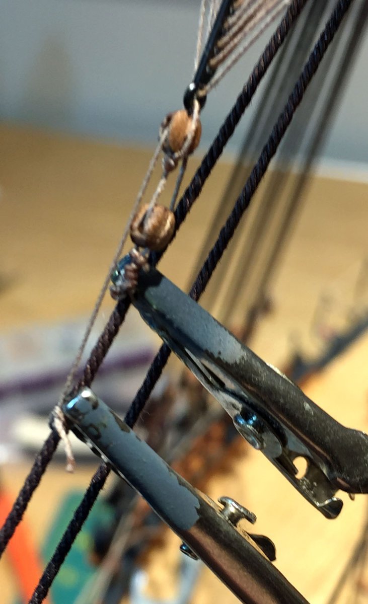
BEFORE you start threading the lines between the top and the euphroe block, secure the euphroe tackle at two points as shown in this photo. I use my smallest alligators to hold the lines in place. This keeps the assembly from slipping upward from tension on the rigged euphroe block, and, if not secured - TEMPORARILY - you'll wrestle with attempts to get the proper results that the rigging process requires.
Once you've tied-off the full crowsfeet run to the top, you can remove these clips and affix the best position of the two tackle lines on the stay and apply a drop of glue so the tie points don't move or slacken: you may need to "slide" these tie points up or down a couple millimeters to accomplish the best tautness to the lines.
For reference, these two tackle blocks are 3 mm single sheave, pear. The line is the same .20mm line used for the crowsfeet.
- Thukydides, Theodosius, ccoyle and 11 others
-
13
-
 1
1
-
21 hours ago, glbarlow said:
Are you following the rigging plan for blocks and rope sizes or a different one?
The quick answer is that I'm referring to Chris' plans as well as relying on past experience of rigging similar 18th-century Royal Navy warships.
You'll see in my last post that I re-rigged the main mast stay, because following the instructions and plans in the kit - was in error. This involved both an incorrect block as well as rope size. Generally, the sequence of rigging is my own although the provided plans are always helpful. As I proceed to rig, I use a marker to highlight a rope line once it's completed. This helps to visualize what has been accomplished and what remains.
I've also substituted nearly all the kit's blocks with upgraded versions, typically falling in the range of 3- 5mm. My posts that explain why I use violin blocks is pretty self-explanatory: these blocks are NOT furnished in the kit. I also rarely use any of the rigging "thread" provided. When substituting real rope I generally downsize by one incremental step; e.g. a plan calls for 1 mm dia. rope, I use the next available thickness, which is .8mm typically. This also depends on my choice of rope vendor now. I do this "downsizing" throughout the rigging process and you've likely spotted these minor changes that deviate from Chris' plans. Many of the upgraded blocks will not easily accommodate the plan-specified thicker rope sizes either.
- druxey, mtaylor and chris watton
-
3
-
2 hours ago, Blue Ensign said:
Post One Hundred and Twelve.
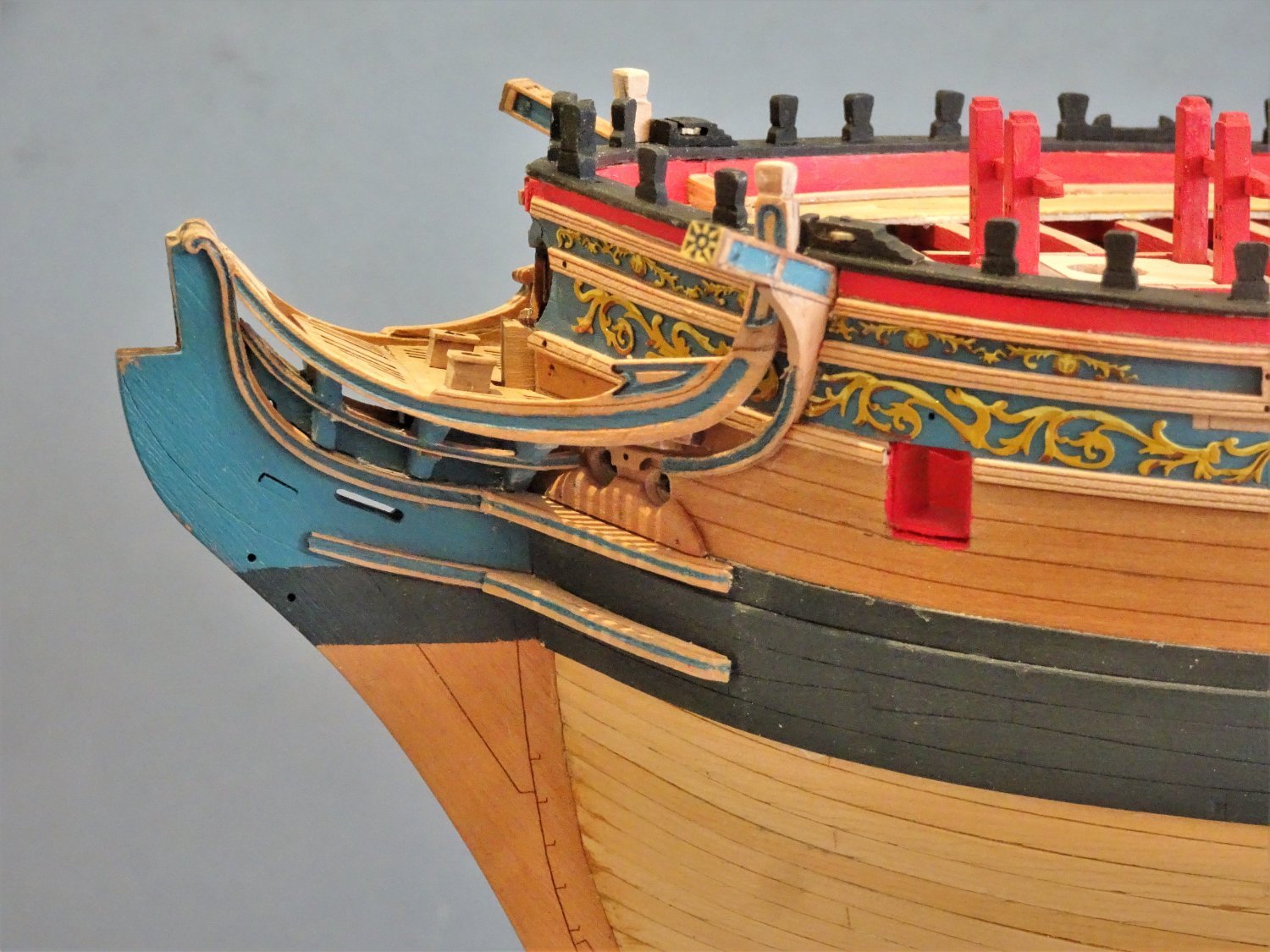
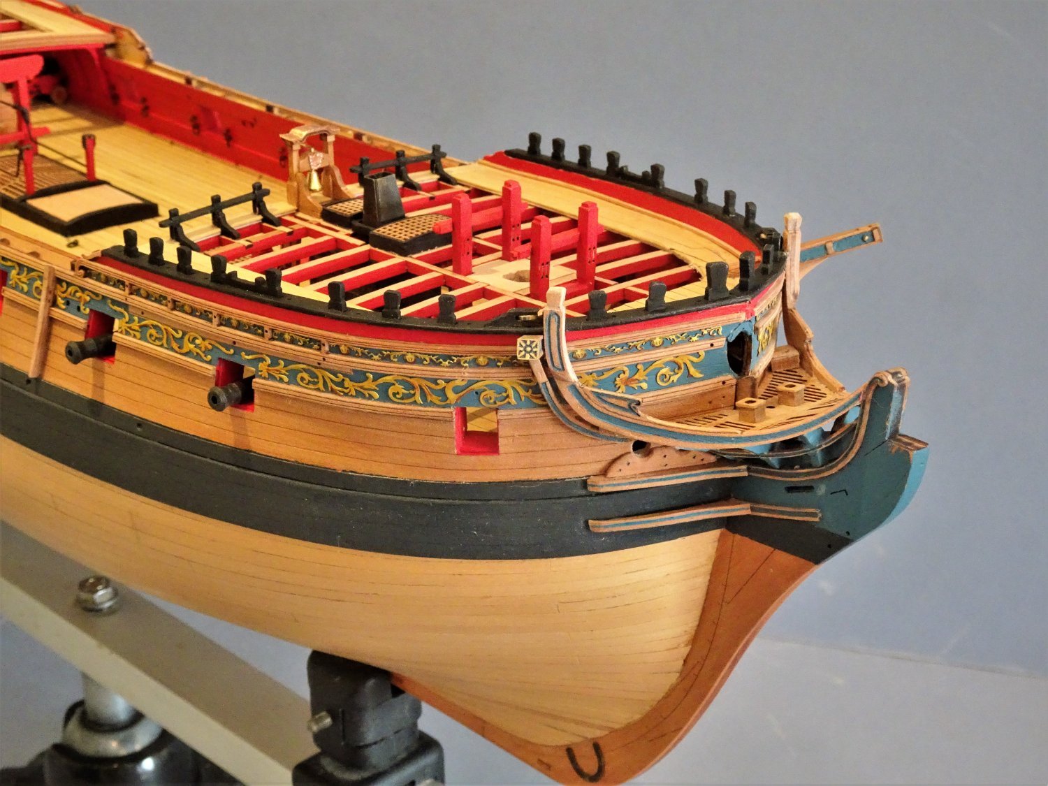
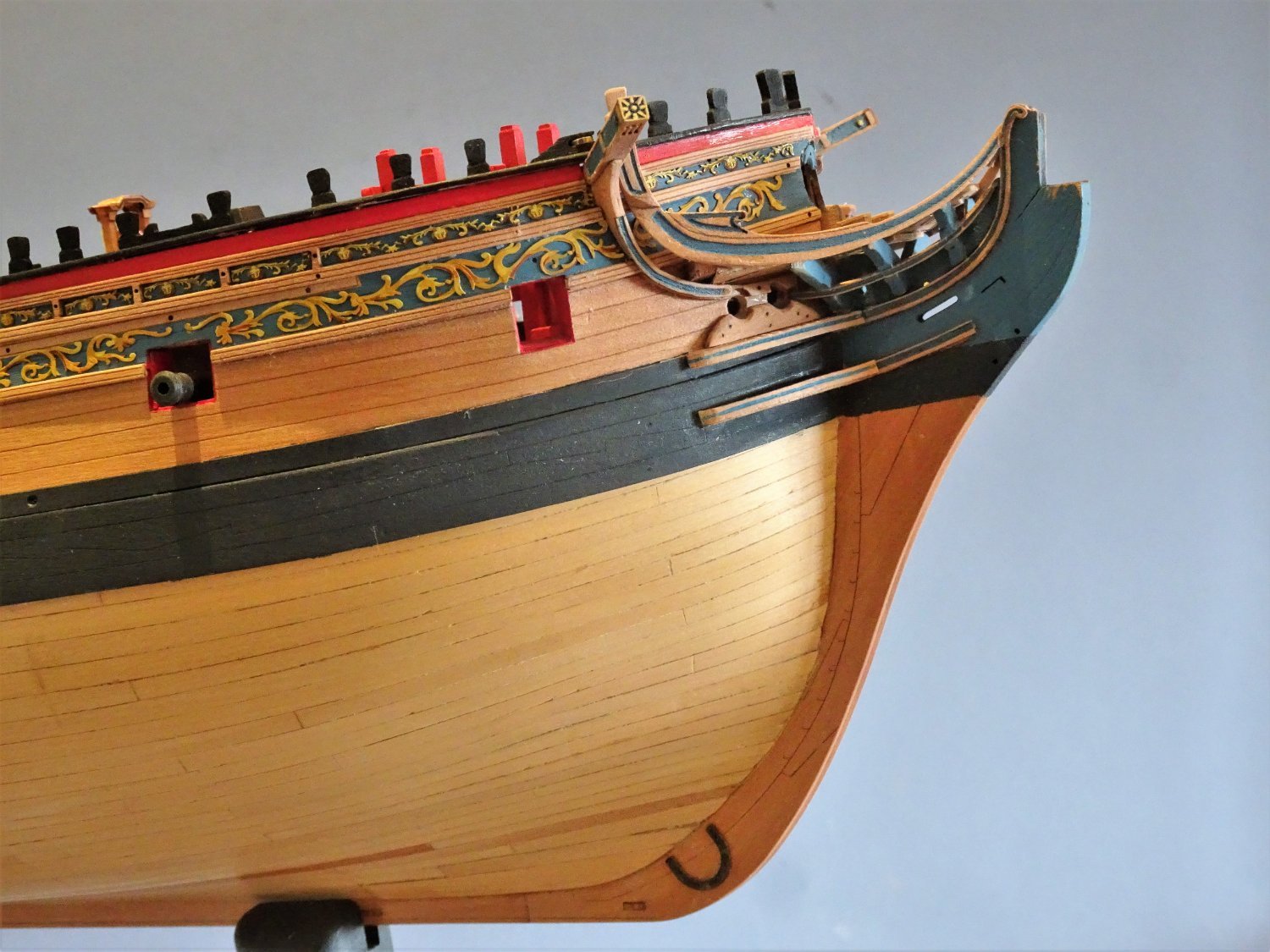
The Headworks.
This, together with the stern have a deal of visual impact and need to look good.
Some of this work has already been completed, the Head timbers, Upper and Lower Cheeks, and their associated Eking Rail and Hair Brackets.
I had not yet fitted the grating pattern in place as indicated much earlier in the build, but this is now the next step.
The Main Rail
There is no denying, Main Rails are tricky, but Chris has produced a version that replicates the elegant curve up to the head and is the first model I have made where I haven’t had to replace this element.
It is a three-section assembly which gives a combined thickness of 3mm at the head tapering to 1.8mm at the bow.
.thumb.JPG.afe7e54afad094f915134d18650737b8.JPG)
6617(2)
As a simplification the False rail has been made part of the overall laser cut part, but ideally it should be a little thinner than the Main rail to which it would have been bolted.
There is an outer section that beefs up the timberhead and stands proud of the rail. This creates the Stepdown which is a feature of the Main Rail. This benefits from a little light paring down to meet the lower level.
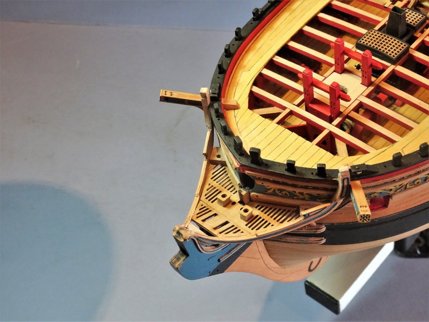
Fitting the Rails
The blurb gives a two-line instruction The rails can now be fitted to the bow as seen here and on plan.
If only it were that simple! Yes, it can be, but the fit will be less than desirable.
The forward tip of the rail fits nicely over the inner side of the Hair Bracket, but it seems to me that for the upper part of the Rail to sit correctly the back edge needs to be notched to fit over the Capping rails overhang and the Upper Hull rails.
I start by holding the forward end in place and mark on the inner end where the upright crosses the hull rails. An angled notch is cut in the upright from aft.
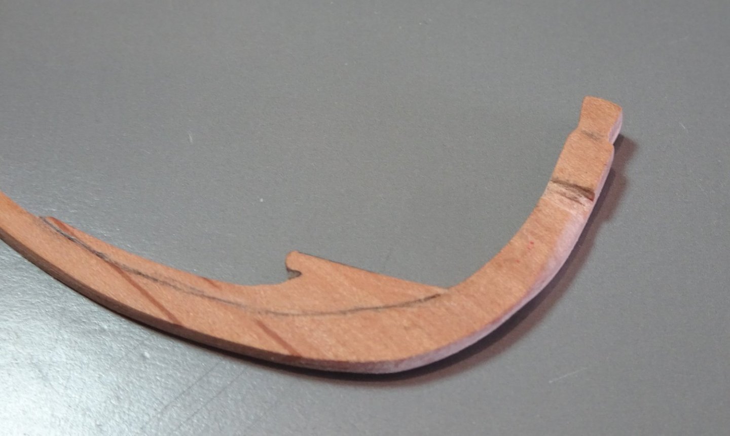
6621
None of this will be seen with the Main rail in place.
I also found it necessary to shape the grating pattern a little at the Fore end for a tension free fit.
Ideally it would be useful to pin the Fore end to the Hair bracket but it so fine that the smallest pin I have tended to split it.
I used pva to glue the rails in place knowing that should I need to remove them I could do it without damage.
The following are the macro shots taken purely to give myself pain, otherwise known as highlighting areas for improvement.🙄
6628

6626
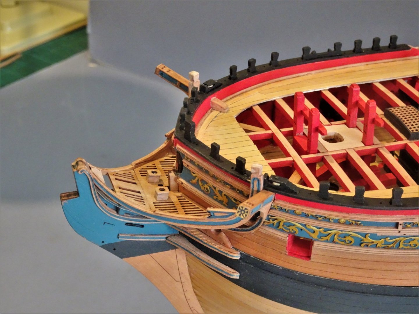
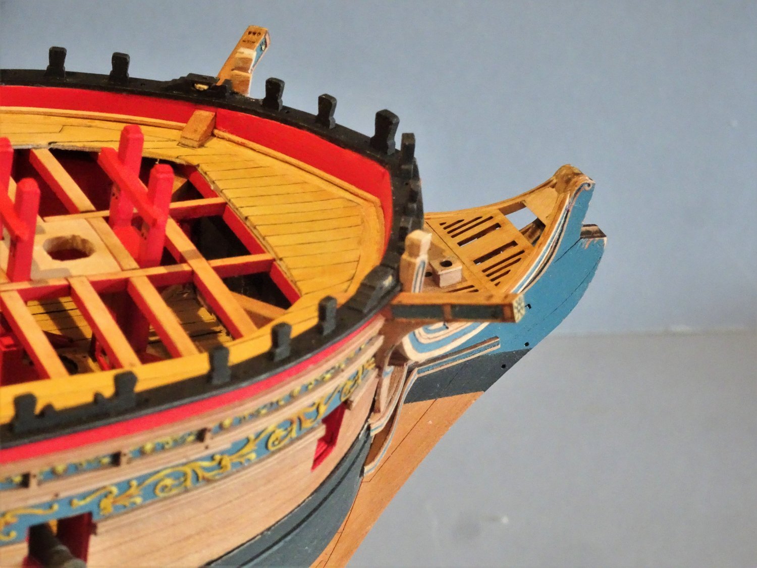
I decided to add a second pair of easement seats fitted between the False Rail and the bow.
I suspect that these seats were far more popular than the exposed pair, but maybe that's just an assumption by a 21st c. man.

6625
6624

6622
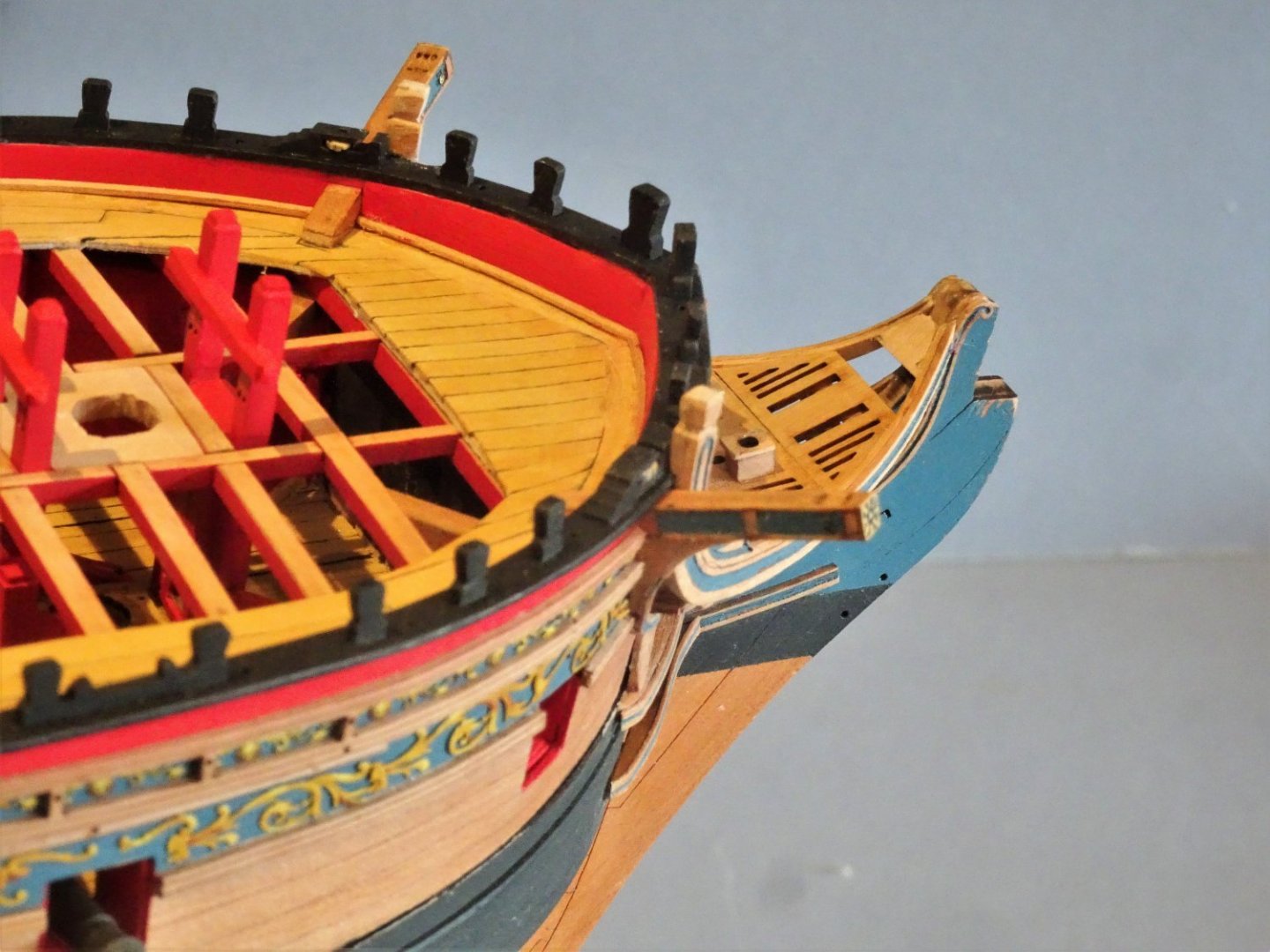
6635
I have added the Saddle where the two rails meet at the bow between the Hair brackets.
6634
.thumb.JPG.13852d40217aaf1c42cdc11b0d68a1ec.JPG)
6632(2)
Still work to do on the bow but overall, I’m satisfied the way the Main rails turned out.
B.E.
On this St George’s Day.
I especially like your continuity of color choices throughout your build. Great job on the ekeing rails, including the coloring. I punted on mine...
-
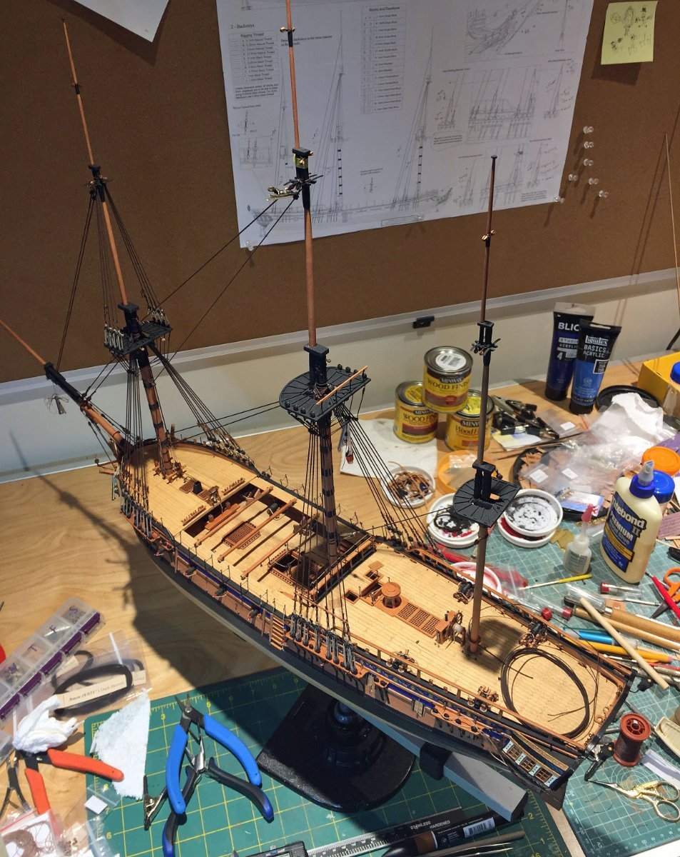
Onward...incremental progress, but progress nonetheless!
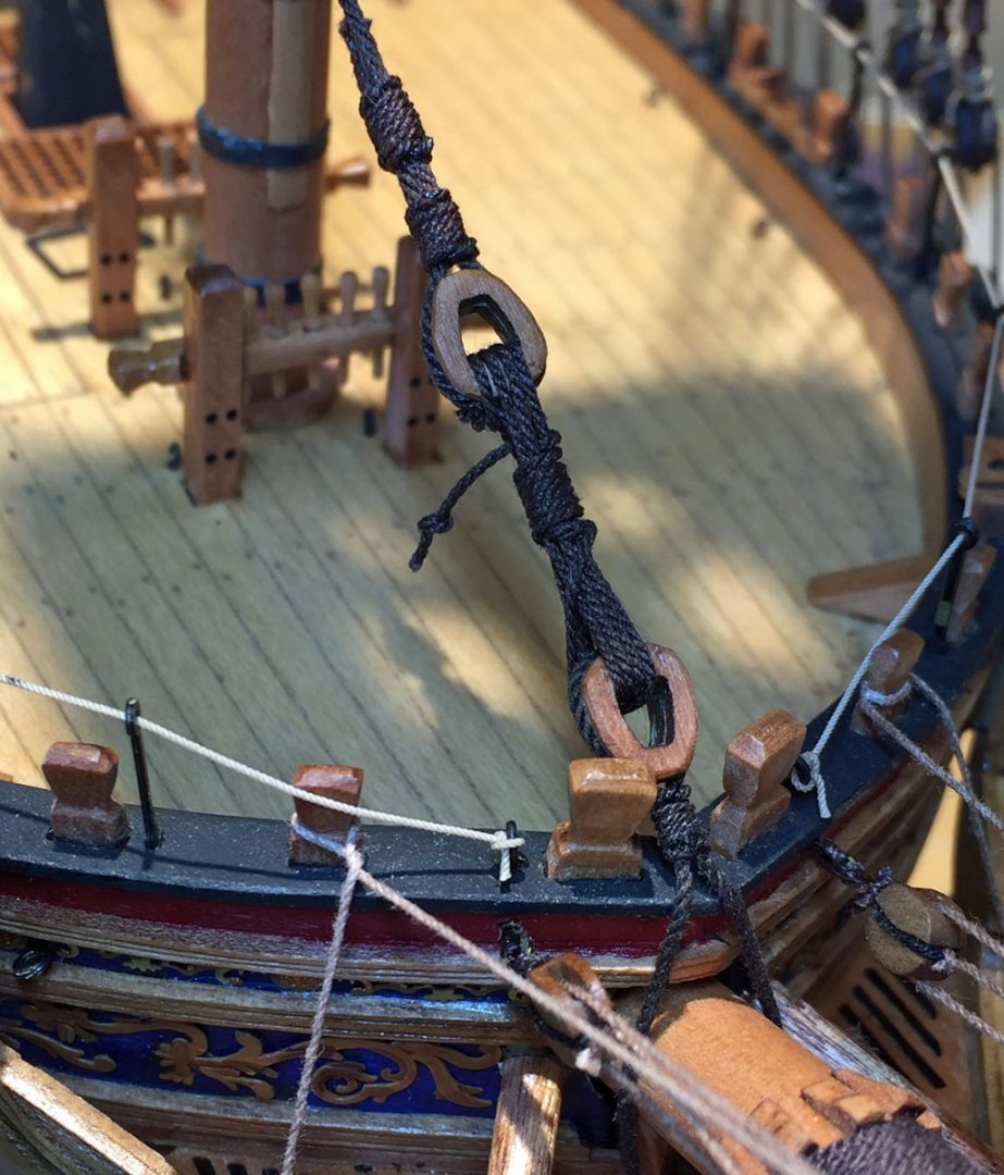
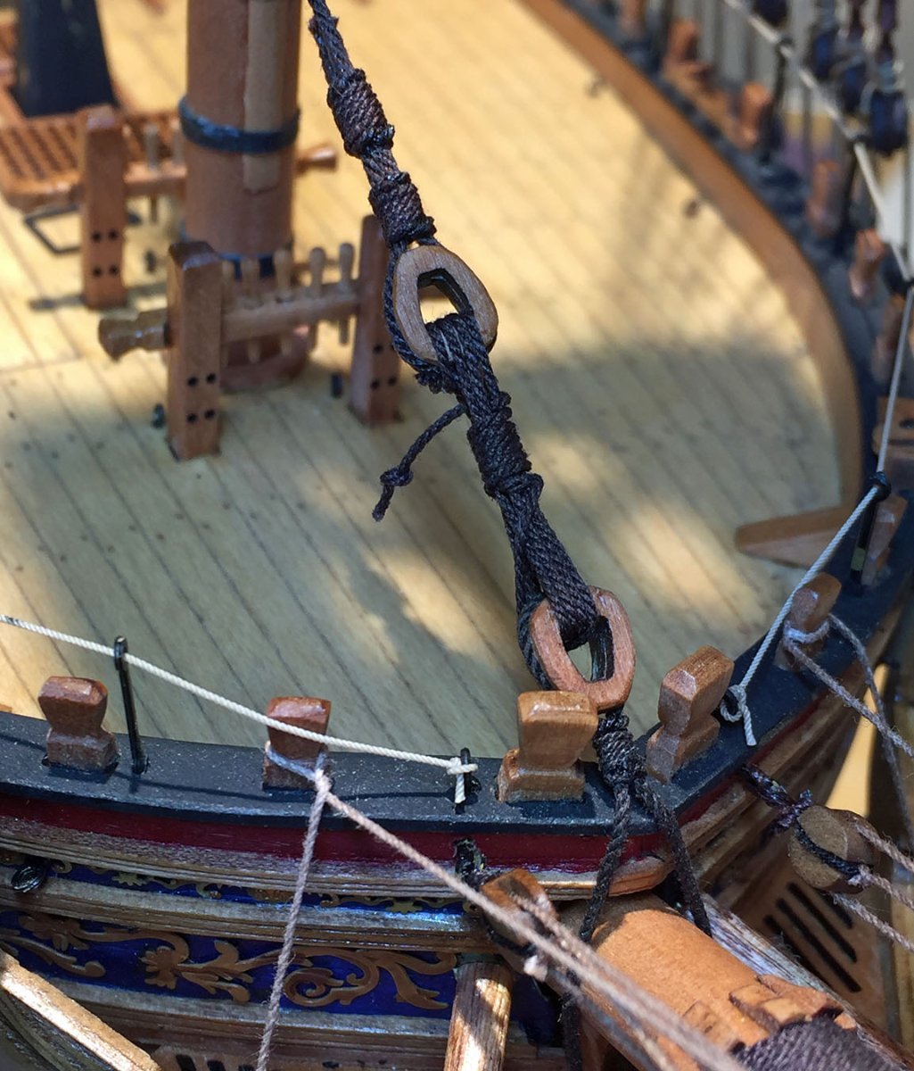
A do-over for the mainstay tackle at the bow.
I'd used an open heart block previously at the bowsprit end and have changed this to a closed heart. At the same time I substantially increased the diameter of the rope that holds this block and then descends around the base of the bowsprit into the stem. This is a much better solution for this critical mast support. In addition, I made the beefed-up rope run between the foremost timberheads (bollards). Previously, my rope from the heart block was on the outside of these timbers - and this was clearly wrong. Thanks to druxey for pointing these details out to me, a man who certainly knows his ropes.🤗
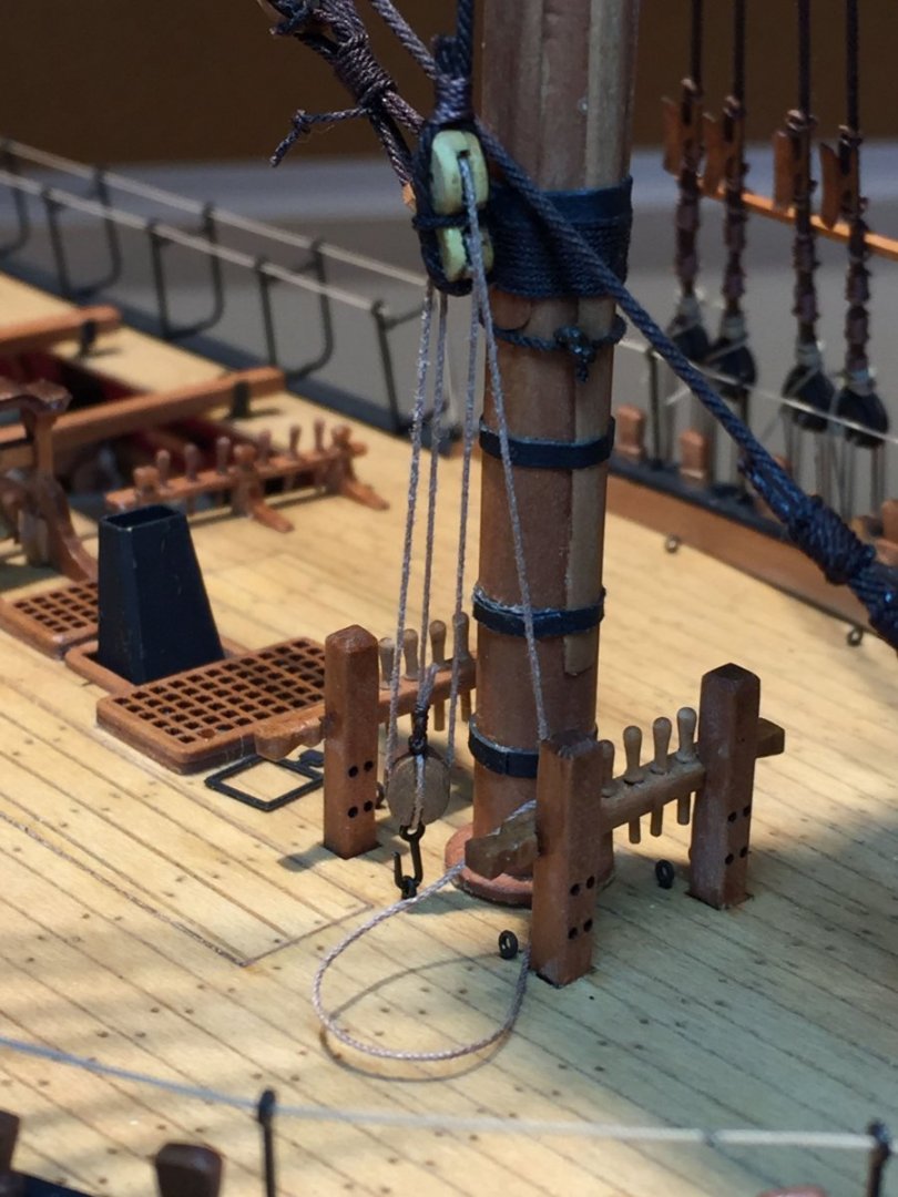
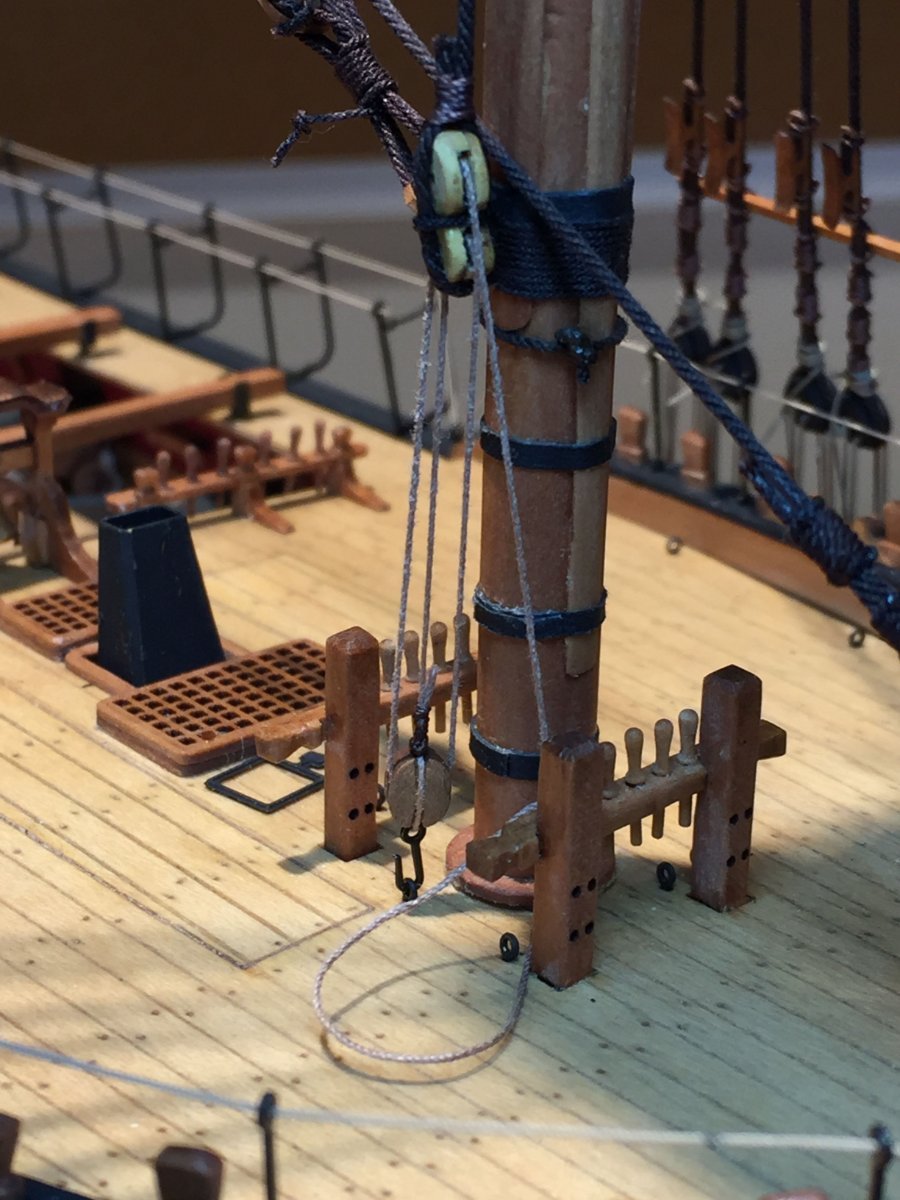
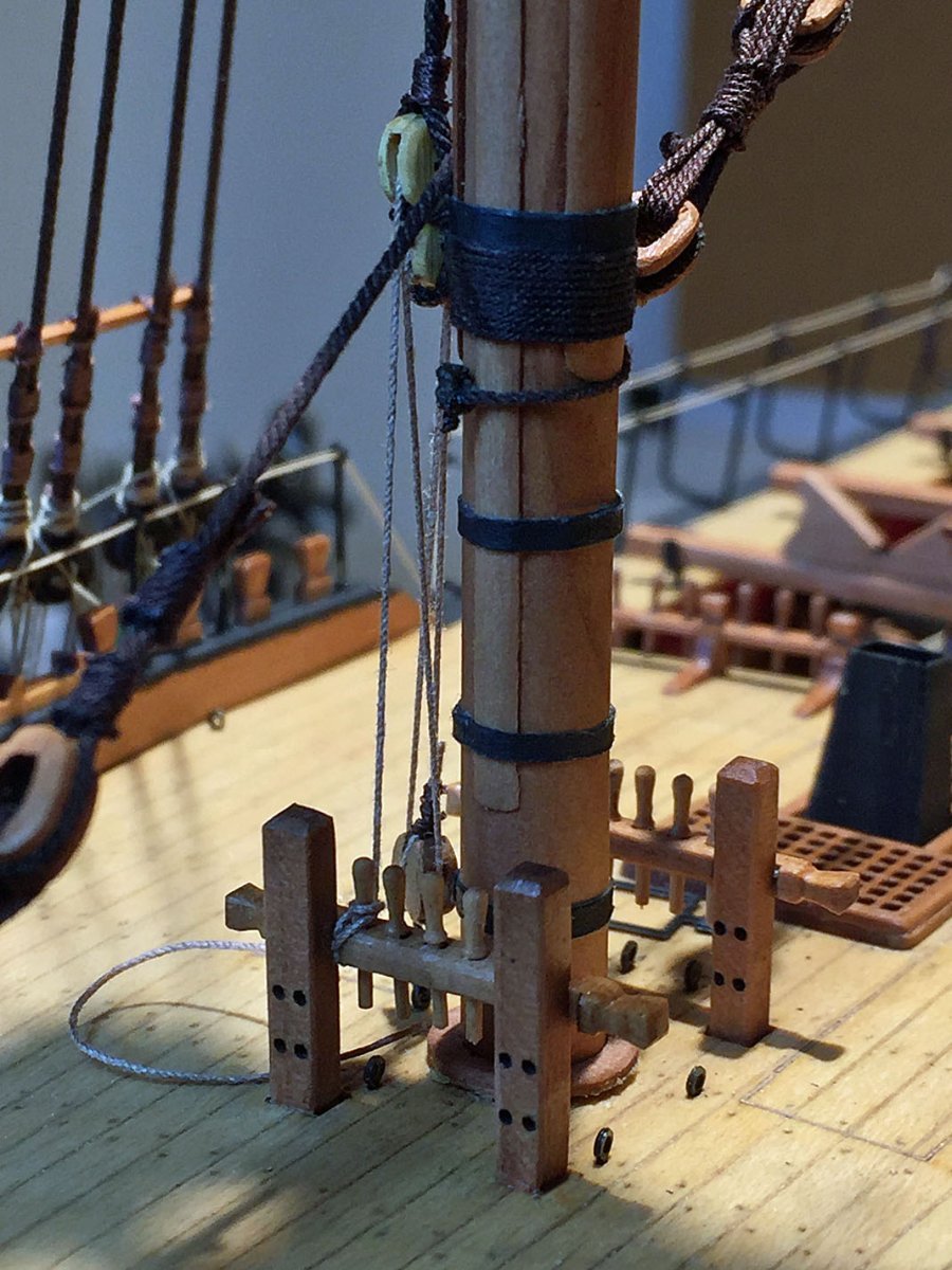
The tackle rigging for the mainmast's topmast stay. The topmast Preventer stay will be rigged to the opposite side of the foremast in a similar arrangement. When my alcohol-based W & N promarker color pens arrive (soon, I hope) I'll carefully attempt to color these boxwood blocks. Better to do this BEFORE rigging I realize, however...there are plenty more that await coloring. I'll see how this coloring of boxwood works out (burnt sienna); my experience is that the density of boxwood requires more than one application.

Another view of the tackle rigging fall line dressed to a belaying pin at the base of the starboard foremast. Once all the rigging is dressed to their proper locations (chocks, blocks, bitts, belaying pins, etc.), I'll add various sizes of coiled rope hanks that will be prepped off the model.
In this close-up I noticed the mast coat has popped-up from the deck. This likely happened due to movement by the mast during its rigging. I'll squeeze a tiny drop of glue under the edge, push it down.
Had I not taken these specific close-up photos I may not have noticed this! For reference, most of my rigging closeups are approximately 600 to 800% enlargements of the actual model size.
- mtaylor, Paul Le Wol, BobG and 8 others
-
11
-
On 4/23/2022 at 4:34 AM, Nipper said:
Ron
What thickness is the upholstery thread that you are using? I'm using some fly-tying thread for my model but it's too fine and difficult to handle. Presumably you have other colours for e.g. running rigging?
Nipper
The upholstery thread I'm using is .20mm or .008 thick. I previously said it is polyester. This is wrong, it's nylon.
I'm using a "Beige" color rope for my running rigging; I'll use five different thicknesses when I get to this stage. The beige color resembles natural hemp. You can see this rope and its color in my deadeye rigging ropes as well as the ropes for the hammock cranes.
-
On 3/25/2022 at 8:49 PM, lraymo said:
Love the pictures of the officers and the crew! These are great (although there must've been a rule to look "serious" for the camera!) I know you were using these as construction photos, but I think its equally fascinating to see the crew!
Nice looking model, Keith. Congrats.
On the old photos from the 19th-century (and even early 20th): most people look so "stiff" (even joyless,mostly super- serious), is because the photographer would coach his subjects by asking them to take a deep breath and hold it since the exposures on glass plates (tech of the era) were quite long, even in bright sunlight. Also, try to hold your breath and smile at the same time...can be done, but it's not natural.
- Glen McGuire, Dave_E, FriedClams and 5 others
-
7
-
1
-
7 minutes ago, druxey said:
Ow! Like burning down the house to get rid of a spider.... You were lucky not to ignite the whole ship. Glad you were able to repair battle damage. Another great reason to use PVA: it can be easily dissolved in rubbing alcohol. As long as you keep open flame away from it!
Yep, druxey. A bonehead move. I usually have a bottle of alcohol handy too. Will an 18 yo single malt Dalwhinnie work?
- Ryland Craze, druxey and mtaylor
-
3


.JPG.392ecc31083dafe0be50e35c36d871ce.JPG)


.JPG.94e3c59f2199ff35c4f8dd3cb88df4b4.JPG)
Chris Watton and Vanguard Models news and updates
in Traders, Dealers, Buying or Selling anything? - Discuss New Products and Ship Model Goodies here as well!!
Posted
I have a solution! Purchase these for your wife this Holiday Season. Tell her they're trending on Instagram and are VERY fashion-forward. An important step before gifting: carefully adjust the diopter controls so that your model appears to be less than half it's actual size...I think these special glasses are mainly sold as a dieting option, however, they would be worth a try!