


Dr PR
-
Posts
2,472 -
Joined
-
Last visited
Content Type
Profiles
Forums
Gallery
Events
Everything posted by Dr PR
-

Carriage Gun Rigging
Dr PR replied to Dr PR's topic in Discussion for a Ship's Deck Furniture, Guns, boats and other Fittings
Here is a drawing from Ordnance Instructions for the Unites States Navy (1860). It shows the method of pointing a gun at an angle to the centerline of the ship. For the big lumbering square rigged ships of the line what wefalck said is probably true. But there are accounts of smaller, more maneuverable vessels like schooners pulling up off the quarter and out of the firing field of larger ships and blasting away at them. In this case angling the guns toward the target would be useful. Pivot guns apparently were often used this way. In any case the Navy seems to have thought it would be useful to train gun crews to point their guns at different angles.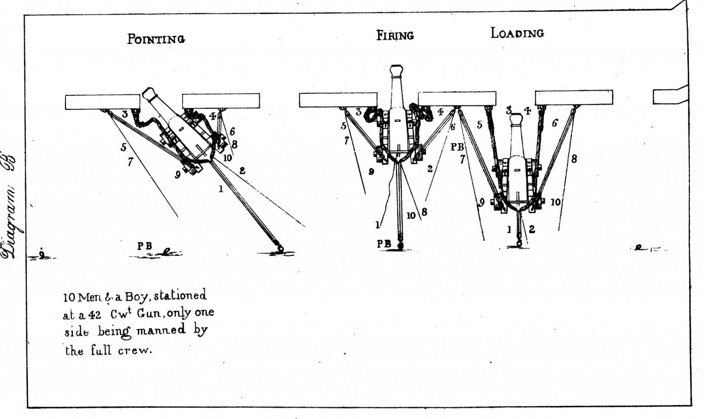
-
Some wooden hull vessels had a thin layer of oak sheathing applied over the normal hull planks. The sheathing consisted of planks attached to the hull to protect the hull in places where it could be damaged by objects being lowered/raised over the side. This sheathing was replaced when it was damaged. In two cases I know of the planks were not tapered. In one case the entire underwater hull was covered with thin sheathing, and the planks were not tapered. Does anyone have any information about how these planks were applied? What pattern? How do you plank a hull without tapering the planks?
-
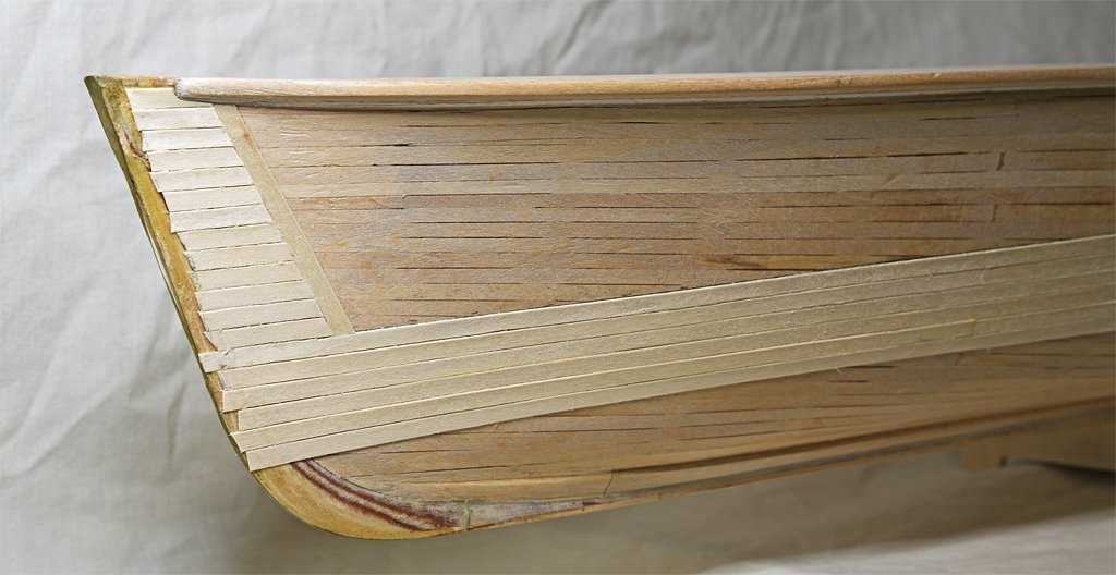
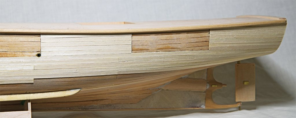
Gary, About the epoxy and the Navy. I don't know how far back that goes. But we did use epoxy paint in the missile house and warhead magazines because we couldn't paint in those spaces while ammunition was loaded. So it was a big project to offload everything at a Weapons Depot and repaint the magazines. However, the grey paint that was used topsides seemed to me to be water soluble and had to be repainted continuously. When I asked our Weapons Officer why epoxy paint wasn't used topsides he replied that there wouldn't anything for the crew to do to keep them busy. "Idle hands are the tools of the devil ..." So they chipped paint. I don't like how this planking is turning out. I have finished the sheathing down to the bilge keel. The planks from the bow are at a sharp angle to the planks from the stern. I have no way to know how they should come together. It looks like a mess to me!
- 492 replies
-
- 3
-

-

-
- minesweeper
- Cape
- (and 1 more)
-
Sheet Metal Shear Recommendations?
Dr PR replied to DerekMc's topic in Modeling tools and Workshop Equipment
Derek, I do not have a shear right now. I used to use the one in our shop at work - but it was a 48 inch wide cutter for large sheet metal work. I like the looks of the 8 inch machine grsjax posted the link to. I think MicroMark used to sell one similar to this. Sorry to say Trump's Hobbies has closed. Jim was at retirement age and Internet competition was really hurting the business. He tried to sell the business but had no serious offers. -
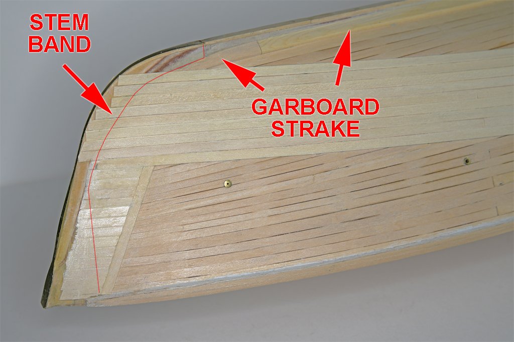
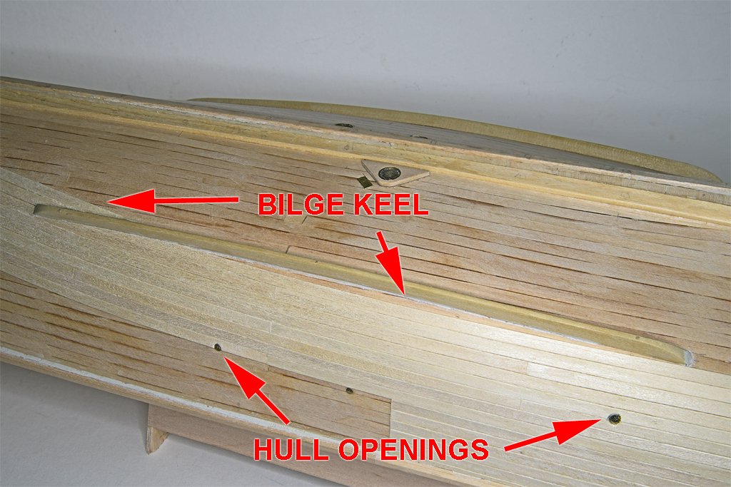
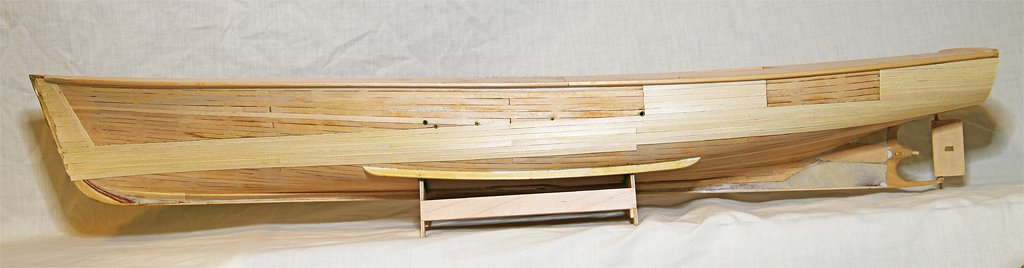
Here are a couple of photos to show the "lay" of the sheathing. On the real ship this sheathing was made of 3/4 inch thick red oak planks. The blueprints say nothing about how to place the planks around the bilge keels - but they do say to cover the bilge keels with the sheathing. Tricky! But you can see how I am trimming the planks to fit up to the bilge keel. The blueprints say to trim the sheathing around hull openings, rudder plates, seachests and the stern frame. I will have to relocate the sacrificial anode adjacent to the starboard sea chest. Here you can see how the sheathing planks meet the garboard strakes at an angle, rather than being spiled to run along beside the garboard. The blueprints say to cover the garboard strake and the keel with sheathing, but to not cover the worm shoe (it is also made of red oak). The thin red line shows where the brass stem band will fit over the sheathing. The sheathing planks will be tapered gradually to zero thickness where they meet the stem so the stem band will fit smoothly over them. It's "deja vu all over again."
- 492 replies
-
- 9
-
-

-
- minesweeper
- Cape
- (and 1 more)
-
Gary, Thank you very much! This is not only interesting information about fishing boats, it does help me understand the origins of this practice. Interestingly, the Cape's planking was 3/4 inch red oak, even though the ship was built in Washington State where Douglas fir was abundant and cheap. You mentioned trim to protect the end grain. A vertical angled strake behind the bow sheathing is shown on the MSI blueprints, and in the photos of the bow of the current Cape. The blueprints don't say anything about how the sheathing was applied between the bow and stern! My photos of the ship in the 1960s don't show this end grain protection for the sheathing farther back along the sides. But the pictures are pretty grainy and hard to interpret. Do you think it should have vertical pieces to protect the end grain? Not tapering or spiling the planks really goes against the grain (pun intended) of everything I have learned about wooden hull construction. I am now carefully cutting the planks to sharp points where they fit around the bilge keels. And soon they will be tapering to fit the garboard strakes. And somehow the planks will have to flow off the after curved hull surfaces onto the flat deadwood and stern frame around the prop and rudder. The blueprints show them running parallel to the bottom of the keel on the deadwood at the stern. I don't know how this will turn out! **** I have been following and admiring your Pelican build. You are doing a beautiful job.
- 492 replies
-
- 4
-
-
- minesweeper
- Cape
- (and 1 more)
-
Sheet Metal Shear Recommendations?
Dr PR replied to DerekMc's topic in Modeling tools and Workshop Equipment
Derek, It looks to me as if the shear you posted the link to is just a crude cutter. A good metal brake (shear and bender) has a "table" on one side that you rest the piece to be cut on, and adjustable stops on the other side to control the width of the piece being cut. You place the work piece on the table with the knife blade up, push the piece through beneath the blade until it contacts the stops, and then cut. This allows you to cut many strips of exactly the same width. A good shear will also have multiple "clamps" that lower with the blade, contacting the work piece and clamping it to the table just before the blade cuts the metal. This prevents the cutting forces from twisting the metal during the cut. The device you posted a link to doesn't have a wide enough table, no stops, and only the one clamp that will not prevent the piece from moving during cutting. It is better than scissors only in that it can cut thicker metal. But it is just for chopping the ends off of longer strips. **** A break will also have bending feature. This is usually a lower fixed "V" groove, with an upper moving "V" shaped piece. It doesn't cut the metal, but just bends it 90 degrees. You can also get tool pieces to bend different angles and different shapes These tools usually have sets of the upper "V" pieces of different widths so you can make bends of varying lengths between other features in the work piece. Like the shear, the bender will have a table to feed the metal into the bender, and will also have adjustable stops so you can feed the piece in the correct distance before bending. This allows you to make repeated bends of pieces with the same dimensions. **** Here is an example of a tool with these features. It also has a sheet metal roller for creating controlled radius curves in sheet metal. https://micromark.com/products/3-in-1-metal-worker?keyword=metal shear If the price is a bit too steep, or it is too large for your work space, you should also look into photo etch bending tools. These are good for thin metals. They are not as sophisticated as a real shear and break and do not have a shear. For brass thinner than 0.015 inch (0.4 mm) you can make cuts with a knife. Just clamp the metal to be cut with a steel ruler placed along the line to be cut. Then draw the knife blade (a dull blade will work) along the ruler edge repeatedly until it cuts through the metal. -
Per, thanks. Shooter, When I was in training for the Talos system everyone was talking about missiles that could be stored like "telephone poles" - just put them in the magazine and forget them until you were ready to fire. They should be more reliable, and there was much less danger from handling them all the time. Talos missiles had to have the NiCad batteries recharged and replaced every month, and the entire electronic and hydraulic system tested every other month. That kept the missile crew busy round the clock babysitting 44 missiles. And that increased the danger of mishandling. We had 13,200 pounds (6.6 tons, 5,987 kg) of class A high explosives and 176,000 pounds (88 tons, 79,833 kg) of class B explosives in the missile house. Plus the capability of carrying nuclear warheads. It just wasn't a good place for handling accidents! I am not familiar with how much servicing the newer Aegis system missiles need, but just storing them in the vertical launchers without having to move them around all the time makes the system much more reliable and safe!
- 54 replies
-
- 2
-
-
- 3d cad
- cleveland class
- (and 1 more)
-
I have been working on the hull sheathing while finishing the topsail schooner build. The rounded edges on the planks created by the draw plate do a good job making the gap between planks. The biggest problem so far has been glue (Sig-Bond Cement) squeezing up between the planks. If it hardens it hides the gaps, so I must wipe off as much as possible immediately after placing the plank. Then I drag a sharpened wooden toothpick point along the groove to gouge out any remaining glue. This also tends to spread the planks a bit, enhancing the gap. The planks are so thin (0.015 inch or 0.4 mm) that they conform to the curves of the hull without any special bending, and are held in place by the wet glue. Nevertheless, I use blue painter's masking tape to hold down the planks until the glue sets. The planks at the stem will be covered by the brass stem band. First I will carve them to zero thickness at the "rabbet" where the hull planks meet the stem so the stem band will conform to the shape of the planking. After the glue sets, if any of the planking gaps are obscured, I pull an old #11 knife blade with a broken tip along the gap, dull side first, to scrape out any dried glue. I can see painting the hull will be interesting because I don't want the paint to obscure the gaps!
- 492 replies
-
- 9
-
-
- minesweeper
- Cape
- (and 1 more)
-
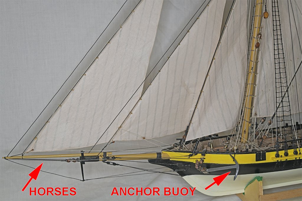
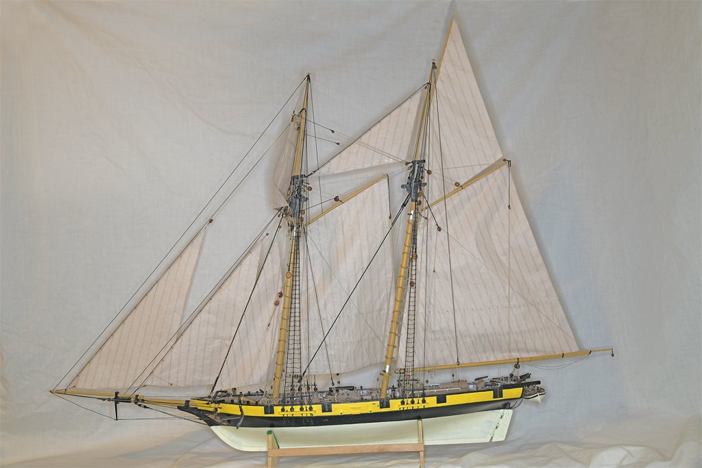
The port ratlines are finished!!!!!!!!! The model is almost finished! There are only three things left to do (that I can remember now). First I need to figure out how the port anchor buoy should be handled while the anchor is being fished. Was it pulled out of the water first before the anchor was fished, or left in the water while the anchor was fished? While the crew is fishing the anchor, if the buoy is brought aboard, what did they do with it while handling the anchor? Second, I need to add horses (foot ropes or man ropes) under the jib boom. Third, there is the chafing mats or serving on the main boom topping lift. I need to check my to-do list to see if there is anything else I have forgotten.
- 421 replies
-
- 11
-
-
-
Carriage Gun Rigging
Dr PR replied to Dr PR's topic in Discussion for a Ship's Deck Furniture, Guns, boats and other Fittings
Thukydides, Good point about the thimble(s) being strapped to the neck of the pommelion or cascabel. Why two thimbles? The thimbles or iron breeching ring would solve a problem the cut splice created - the breeching rope would be free to pass through the thimble/ring as the gun is aimed at an angle. This would allow the gun to recoil more in a straight line until the breeching rope pulled tight to stop it. The recoil force would be born equally by both ring bolts in the ship's side. When a gun was fired at an angle with the cut splice the breeching rope would be pulled tighter on the side to which the gun was aimed. Therefore, in the recoil that side would pull tight first and jerk the gun around until the other side pulled tight. Most of the recoil force would fall upon one of the ring bolts. I'm sure gun crews understood that they shouldn't be standing behind one of these things when it fired. But having the gun flailing around a bit more would be "inconvenient." I like your idea that the thimble(s) spliced to the neck of the cascabel would be an evolutionary step toward casting the breeching ring in the cannon itself. -
I Have an Itch to Scratch
Dr PR replied to SaltyScot's topic in Modeling tools and Workshop Equipment
For cutting bulkheads, frames and other curved pieces as scroll saw is very handy. You can do this with a coping saw or jeweler's saw, but the scroll saw is much faster. You can use it for cutting small pieces of any shape from larger sheets. A disk/belt sander is very useful for finishing edges, bevels and such. You can use it for the final trim of parts that were cut out with the scroll saw. The one tool I miss the most is a milling machine. This will allow drilling a sequence of evenly spaced holes in a straight line, like the holes in a pin rail. You can also mill precisely dimensioned shapes with holes and cutouts, like parts for cannon carriages or "mag" wheels for cars. A drill press with an X/Y table is a poor substitute but better than nothing. A drill press is designed for up/down drilling only. A milling machine has bearings designed to take lateral forces, so you can use end mills to rout out grooves and finish surfaces with high precision. I want a small mill that has little runout or wobble (very good bearings). For large drill bits it doesn't matter much, but with small bits it is very important. If the drill bit wobbles the hole will not be round, and small bits will snap off. A ventilated paint booth would be good if you do much spray (airbrush) painting. Or you can do what I do, and wait until it warms up outside and do the painting in the back yard. I find my quilting/wood bending/sail making iron very useful. You need some sort of vise to hold things while you work on them. If you do much work with brass or other metals an sheet metal shear (brake) would be useful for cutting custom dimension strips. A sheet metal bender is useful. If you work with small pieces of thin metal a photo etch bender will do. A soldering iron is useful for working with brass and other solderable metals. -
It's good that you have that problem solved. When we moved my Mother into assisted living (at age 101) she didn't want to leave her home. But she really was lonely there, even though neighbors visited occasionally and she was across the street from my brother. But she really blossomed in the retirement community, making a lot of new friends and becoming the matriarch of the place. Lets hope your mom is as happy with her new home. And you have the plus that when you visit you can also inspect the ship model(s). Did you notice any other models in the place?
-
Mark, The white glue soaks into the threads of cotton and silk lines (I prefer silk) and binds the knots. But it doesn't bind to polyester ropes. So the knot really is free to slide up and down on the polyester shrouds if you tug on it hard enough. But for ratlines that isn't a problem. If you did somehow manage to move the knot you just have to slide it back in place and apply a drop of water to loosen the glue. When the water evaporates the glue will set again. I really like silk thread for seizing and such. When it gets wet it goes totally limp, making tight knots and seizing. Cotton is almost as good when it is wet.
-
Carriage Gun Rigging
Dr PR replied to Dr PR's topic in Discussion for a Ship's Deck Furniture, Guns, boats and other Fittings
Here is a wild guess - just that, a guess. 1. Suppose you cut the breeching rope in the middle (at the cascabel). 2. Then splice a thimble in each end (double thimbles). 3. Run the other end (without the thimble) of one rope through the thimble on the other rope. 4. Repeat with the other rope (the loose end through the thimble of the opposite rope). 5. Now you have an "eye" between the two thimbles that can be slipped over the cascabel. Top: two ropes with thimbles in one end. Bottom: each rope passes through the thimble on the other. This might be easier to rig than a cut splice, and it would be easier to attach and remove from the cannon. REPEAT: wild guess!
-
Best White Wood Glue For Ship Building
Dr PR replied to OldeManToad's topic in Modeling tools and Workshop Equipment
Gregg, Shellac is an alcohol solution. You can keep it in any container that you can use for alcohol. I'm sure the plastic needle-tip applicators will work. Remember that it is an alcohol solution, and the alcohol will dissolve other alcohol-based dyes or alcohol soluble compounds. I used to use shellac to stiffen ropes to get the proper catenary or droop. But I made the mistake of using an alcohol based dye on the blocks in my current build. When I wet the ropes with shellac the alcohol dissolved the dark brown dye and it wicked down the ropes, leaving an ugly brown stain in the ropes near the blocks. Now I have to use diluted white glue to stiffen the ropes! Shellac is available in 12 ounce (340 grams) spray cans (Zinsser Bulls Eye Shellac). This would be handy for covering large areas, as in furniture finishing. But you can spray a small amount into a jar or cup and apply it with a brush or just get a small drop on a needle. I am told it will "go bad" after a while, but I haven't seen this in a can several years old. I also have the shellac flakes that can be dissolved in denatured ethanol to get a desired concentration (cut). Discussions of the "right" way to mix, store and use shellac can develop into almost fanatical arguments. There is a lot posted about it on the Forum. -
Best White Wood Glue For Ship Building
Dr PR replied to OldeManToad's topic in Modeling tools and Workshop Equipment
vaddoc, When the acetone in Duco Cement evaporates it leaves a plastic-like solid. I think it is just dry nitrocellulose, with no chemical curing like other glues. It will fill narrow gaps to a degree, but the volume reduces significantly as the acetone evaporates. In narrow cracks it usually leaves a "U" shaped surface across the crack. So it doesn't really fill the crack completely. However, I have mixed it with wood powder/dust from sanding to make a good crack filler. One other interesting thing - nitrocellulose is gun cotton, an explosive. It is very flammable. But so is wood, plastics, cotton thread and many other things we use in modelling, so that really isn't a problem. I have yet to have one of my models explode! -
Tom, Not all gaffs had jaws and parrals. On many ships the gaffs (and booms) were attached with goosenecks that pivoted in sockets fixed to the masts. The sails were furled by hauling on brails attached to the sail trailing (leech) edge and drawn up to the gaff and mast. In fact, I think this was more common on larger square rigged vessels with "spankers" or "drivers" on the mizzen masts. The gaff with jaws and parrals seems to have been more common on smaller vessels, especially fore-and-aft rigged ships.
- 206 replies
-
- 1
-
-
- Endurance
- Shackleton
- (and 2 more)
-
Andoni, Glad you enjoyed this log. Since the Albatros is your first wooden ship you should worry less about historical accuracy and getting it "perfect," and use it to learn different methods for building things. There are a lot of folks on the Forum who are happy to answer questions.
-
Progress, slowly but surely! The starboard side rat lines are finished. Half way there! The forward ratlines were tied with 0.012 inch (0.3 mm) brown polyester rope. The polyester is springy and the knots were untying themselves as fast as I could pull them tight. The clove hitches on the center shroud weren't much of a problem, but the lark's head (cow hitch) knots on the outer shrouds were horrible. I had to put a tiny drop of Duco Cement in the loose knot and then pull it tight and hold until the glue set (20-30 seconds). CA gel would probably work but you would have to be fast - one slip and it could set before the knot is tight or in the right position. I looked through my modeling materials and found a small spool of what appears to be cotton rope of about the same dimension. It was left over from a previous kit - or perhaps this one! I used this for the after ratlines, and used simple overhand knots. After I pulled the knots tight I put a small drop of diluted white glue (1:1 with water) on them. The white glue soaked in and fixed the knot after it set for half an hour or so. This allowed plenty of time to reposition the knot and pull it very tight. It was MUCH easier than trying to use the polyester! **** Falconer's Universal Dictionary of the Marine (1769) has this to say about "RATTLINGS, enflechures, certain small lines which traverse the shrouds of a ship horizontally, at regular distances from the deck upwards, and forming a variety of ladders, where by to climb to any of the mastheads, or descend from them. Hence the term is apparently derived from rath, an obsolete word, signifying an hill." Webster's Third New International Dictionary says "rat-line also rat-lin or rat-tling [origin unknown] 1. or ratline stuff : small, usu. 3-stranded, tarred rope used for cross ropes on ship's shrouds. Webster thinks rath is an Irish earthwork fortification, perhaps on a hill? "Fairy denizens of rath and hill." And now we know.
-
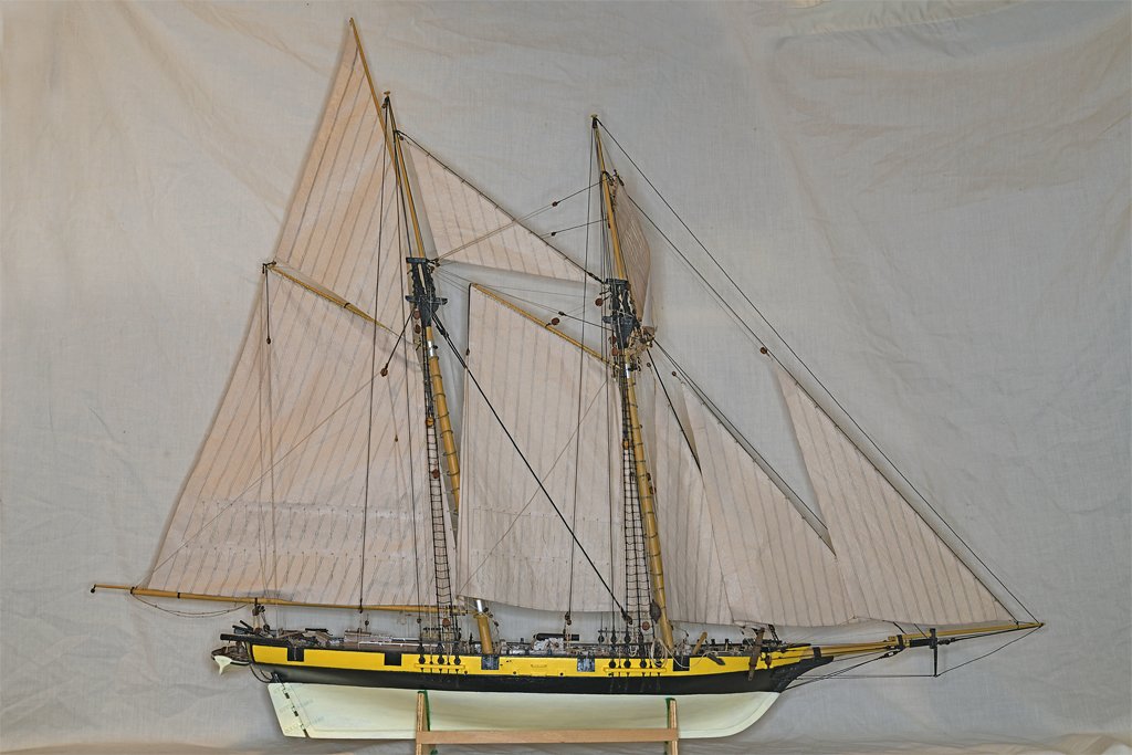
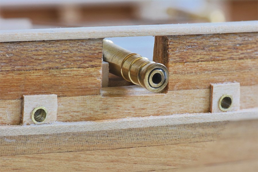
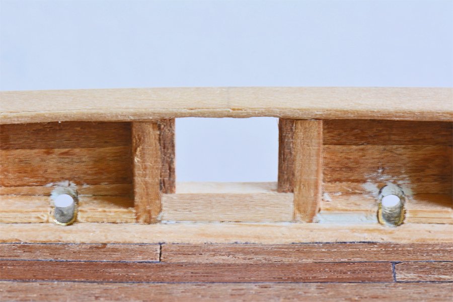
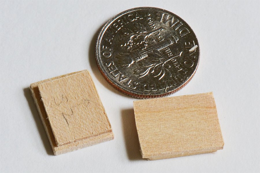
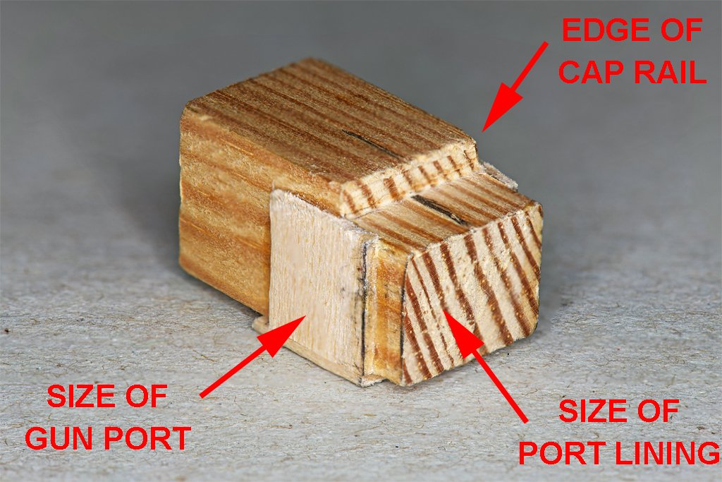
Mark, I was worried about getting all of the gun ports exactly the same size. I made a gun port tool from some scrap wood to ensure that all of the ports came out the same. Can't say this was my invention - I saw it in a book about building the hull of ship models. On the Albatros build the gun ports were cut immediately under the cap rail. The tool fit under the cap rail to the point marked "edge of cap rail," The surface with the black centering mark slid under the cap rail. The gun port opening was cut just large enough for the part marked "size of gun port" to slip fit through. I used files to open the original small drill hole to the right size and shape for the tool to be inserted until the edge marked "edge of cap rail" fit against the cap rail. Then I built up the port lining inside the bulwark so the part marked "size of port lining" slip fit into the lining. The gun port lids fit into the opening and rest against the port lining. The trick is to remove material from the planking slowly until the tool fits tightly into the opening. Here are a couple of pictures showing the results. On the left you can see the port linings inside the port opening. On the right is the view of the inside of the bulwarks showing the lower cill (lighter color wood) and the vertical linings (darker wood) inside the bulwark framing around the gun port. The gun port lids had a thin inner layer just large enough to fit into the lining/cill opening, while the outer layer fit tightly into the port opening and rested against the lining/cill. Hope this helps.
-
I agree with Bill. Don't worry about it. After all, we have examined Chapelle's drawings of the Lynx and Musquidobit and he has drawn the rake angle of the main mast a bit greater than that of the fore mast. So maybe he changed his mind? We will never know what the actual rake angles were. Who knows, maybe what you have decided on is what the vessel really had?! I posted that Chapelle quote with chagrin because I have been reading over everything I could find about this vessel and had missed this bit at least several times!
-
Mark, I just came across something about the Musquidobit in Chapelle's "The Baltimore Clipper" (page 82): "Her spars rake very sharply aft and both masts rake the same."
-
Carriage Gun Rigging
Dr PR replied to Dr PR's topic in Discussion for a Ship's Deck Furniture, Guns, boats and other Fittings
Mondfeld's Historic Ship Models (page 167) says the breeching ring was found on English cannons from the late 18th century and early 19th century. But where did the guns on the Lynx come from? There probably is no record of that, other than they were put on a vessel built in America. Then did the British change out the guns on the Lynx/Musquidobit after it was captured? I looked for the history of the vessel after it was captured and didn't find anything, How long was it in British service? -
Best White Wood Glue For Ship Building
Dr PR replied to OldeManToad's topic in Modeling tools and Workshop Equipment
vaddoc, Duco isn't what I think of as a contact cement. The contact cements I have used are rubbery and sticky when set. You apply it to both surfaces, let it dry until it is tacky, and then press the pieces together. They bond on contact, hence the name. Duco is a solution of nitrocellulose in acetone. The liquid flows into pores and cracks. When the acetone evaporates the nitrocellulose hardens to hold the parts together. In this respect it is just another glue for porous materials. Acetone is very volatile and evaporates quickly, letting the glue set up quickly. However, because it leaves a film on smooth surfaces it can be used to glue wood to metal and metal to metal. However, this is not a really strong bond. The hardened nitrocellulose can be knocked loose from the smooth surface with a blow.


