Dr PR
-
Posts
2,306 -
Joined
-
Last visited
Content Type
Profiles
Forums
Gallery
Events
Everything posted by Dr PR
-
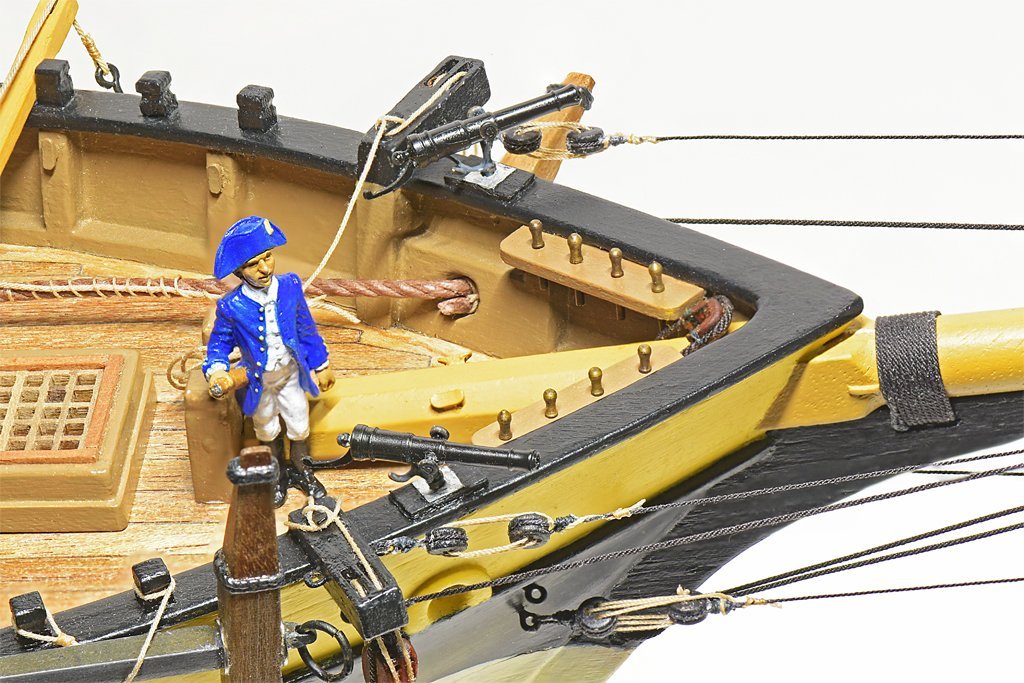
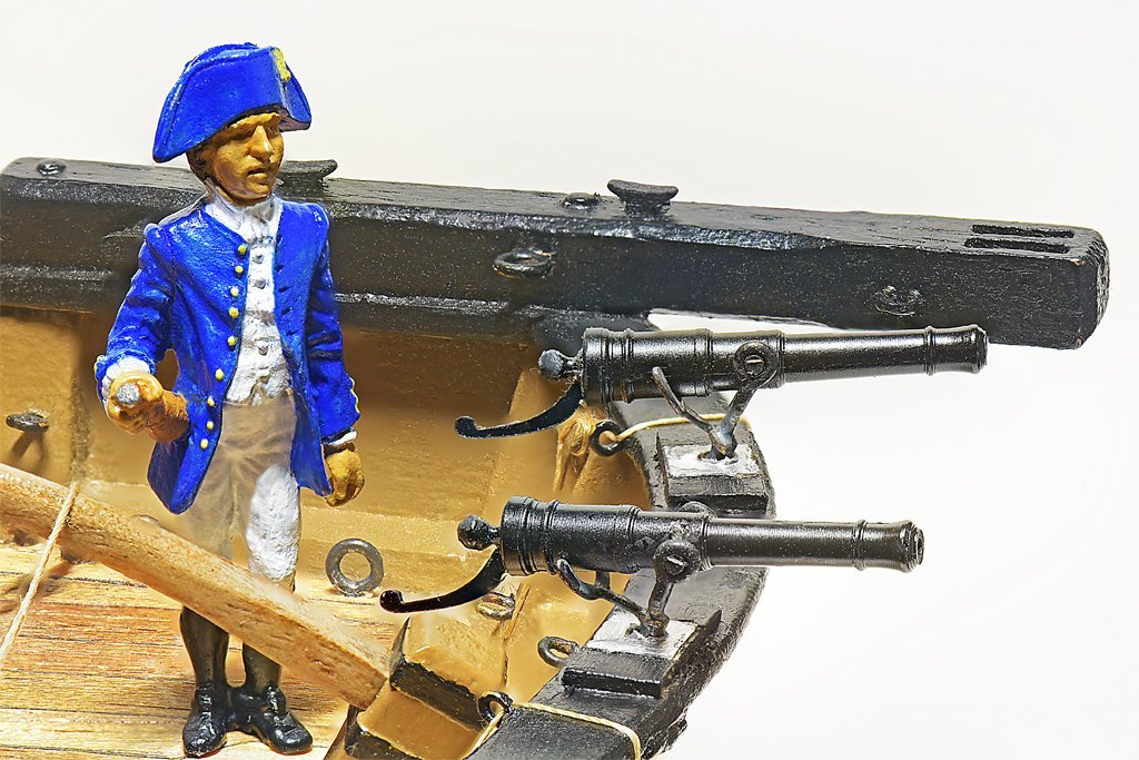
 I am glad you are finishing Chaconia. I love all the piping and cables on that model. You mention the "pose" of the fellow in the photos. It is mostly accidental. More "whatever happens" than "pose." That thing has two small feet, but it will stand up on its own if the surface is horizontal (perpendicular to the Earth's gravitational attraction). However, the vessel's deck has camber, so the figure only wants to stand up on the centerline. To resolve this I cheat - I tilt the model slightly until the figure stands where I want it, and tilt the camera (picture) to compensate. PITA! I have resorted to a small patch of double sided tape that is hidden by the bulwarks.
 -
Focus Stacking
Dr PR replied to Dennis P Finegan's topic in Photographing your work. How to do this.
The phone won't work unless you can adjust the focus manually to set the depth of the focal points. I don't know if any cell phone camera has this capability. However, if it does it might have the automatic focus stacking feature. The macro lens on my cell phone has an EXTREMELY shallow depth of field (less than 1/8 inch (3 mm). It is essentially useless for anything but flat objects. I would have to take dozens (hundreds?) of images at different focus depths to get a set of photos of my ship model for photo stacking. I can get an 11" (280 mm) depth of field with the real macro lens on my DSLR. You can probably get better photos for focus stacking with the ordinary camera in your cell phone. -
Stepping the mast with a plum bob...two questions.
Dr PR replied to HardeeHarHar's topic in Masting, rigging and sails
DO NOT GLUE THE MASTS IN PLACE! After the shrouds and stays are added the masts cannot go anywhere. Careful about using the "waterline level" idea. This assumes the waterline is actually in the correct position. If for some reason it is a bit lower on one side than the other,and you "level" the waterline, then your mast will not be perpendicular to the deck (from side to side) and this will be VERY obvious when you look at the model. You want to get the deck level - as John Ruy shows in his photos. If the model has bulwarks, and IF your bulwark cap rails are the same height above the deck on either side of the mast, you can use the tops of the rails as a reference and level them. I place something across the bulwarks and behind the mast as my horizontal reference. Then I use an ordinary right angle drafting square placed on the horizontal piece to align the mast. This method does not require the hull to be "level" in any orientation. The mast is positioned relative to the hull, and not relative to the Earth. The plum bob will work IFF your deck is horizontal relative to the Earth - hence the spirit level in John's photo. **** It is a bit late to be thinking about stepping the masts when you get to the point you want to start rigging. That should have been done while the hull and deck were being constructed. I show a technique in this post for setting the fore-aft rake and positioning the mast vertical port-starboard. https://modelshipworld.com/topic/19611-albatros-by-dr-pr-mantua-scale-148-revenue-cutter-kitbash-about-1815/?do=findComment&comment=599087 I am just getting to the point I want to step the masts and start rigging. When I temporarily install the masts they are still perfectly vertical and have the desired rake. However, experience tells me that I can bend the masts from side to side while installing the shrouds and stays. So I will have to be careful and used the actual procedure for installing them, starting on the starboard side for one line/set, then on the port side for the next, back to starboard for the third, etc. The first few stays and shrouds are important. After you get them rigged without bending the mast they will stiffen the structure and resist further bending. BUT IF YOU SET THE SHROUDS/STAYS TO BEND THE MAST YOU WILL HAVE TO REMOVE THEM ALL AND START OVER. -
Javelin, That curse of details is so true! I was designing a 3D CAD model of a winch, and put in all the bolts and such. But close up photos clearly showed the manufacturer's name cast into the gear case. Should I model that also? The letters were cast with compound curve surfaces, and those are tricky to model. I could do it - I have modeled worse - but would take longer to do that the rest of the winch. Well, the letters were about 0.25 inch (6 mm) high and 0.25 inch wide. If printed at 1:100 scale they would be 0.0025" (0.06 mm) high and 0.0025" wide. There was no way that was going to come out legible, even with a magnifier! So why bother? You have to set a minimum size that you will try to model and skip the details smaller than that.
-
Ouch! And ouch again!! I definitely would have had a panic moment when the crosstree broke! In previous builds I breathed a sign of relief when all the lower shrouds were in, the masts were vertical, and the upper deadeyes all lined up evenly spaced.
- 282 replies
-
- 2
-

-
- Bluenose
- Model Shipways
- (and 1 more)
-
Now that is one short, stubby vessel! Are you sure you aren't building a model of Bushnell's Turtle? Seriously, you may have passed the doctor's two week "dust free" mark, but don't press your luck. I would still try to avoid as much dust as possible. You really need to take care of your vision!
-
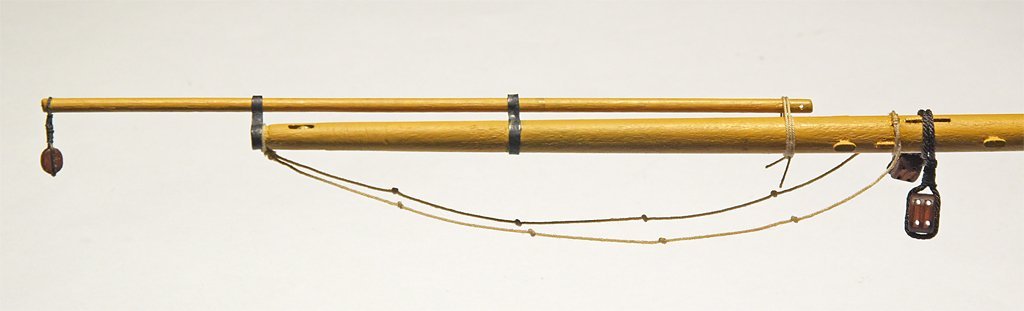
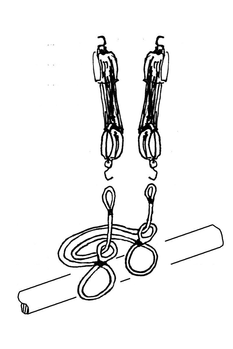
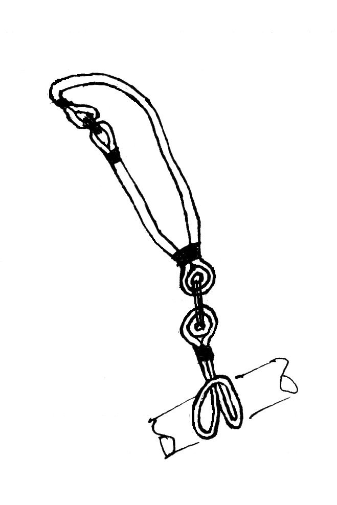
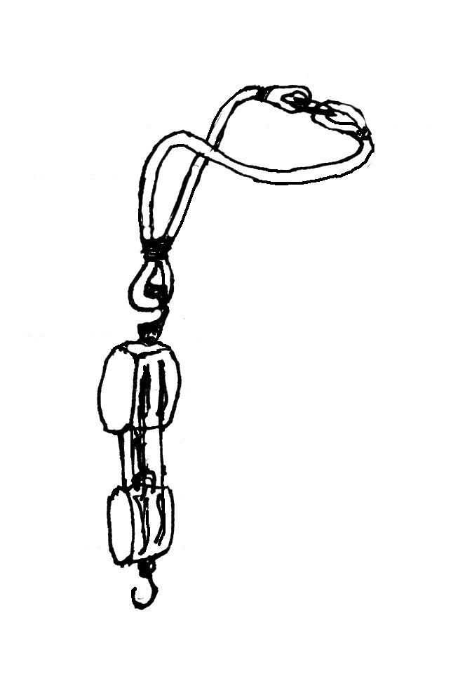
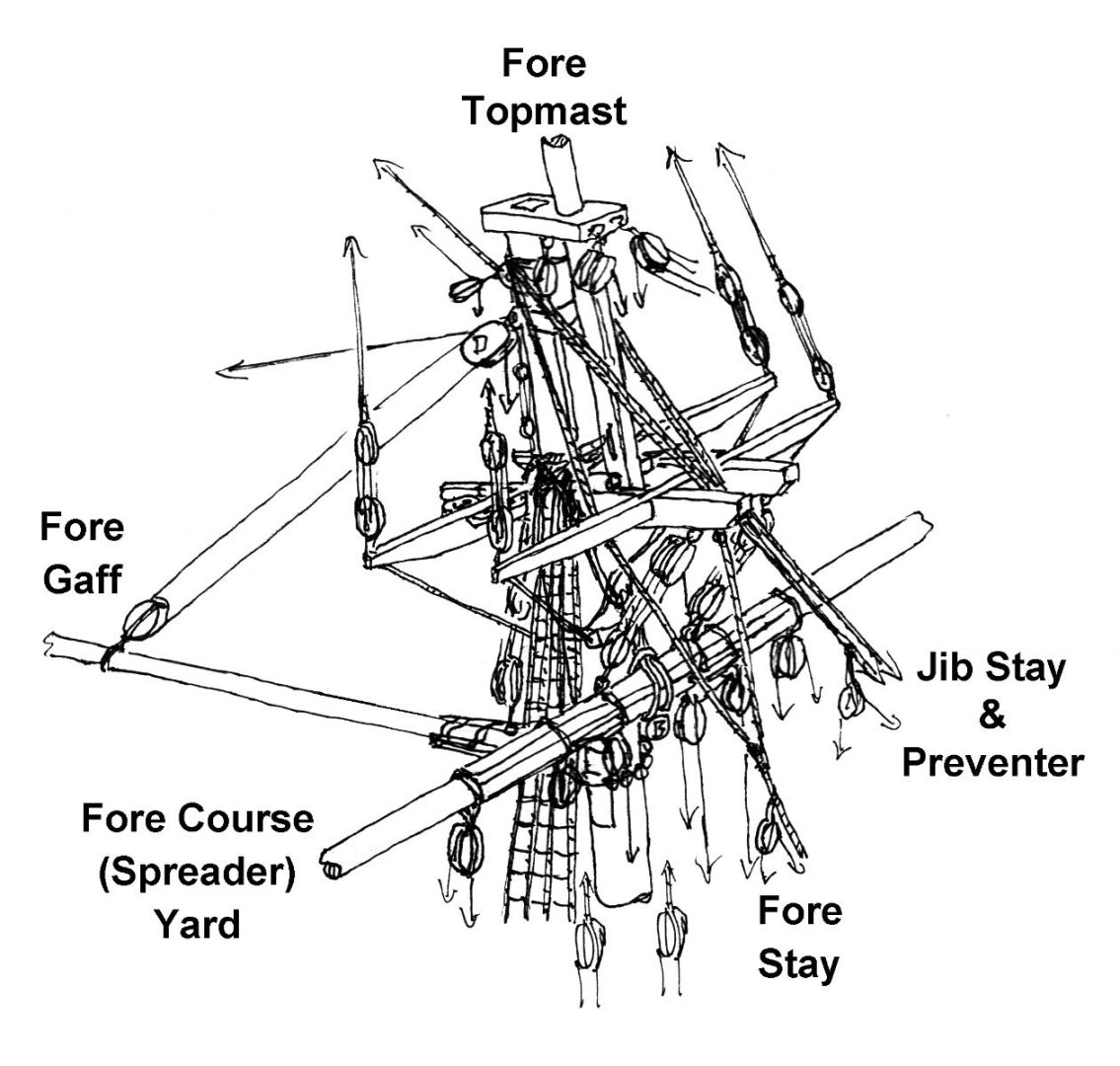
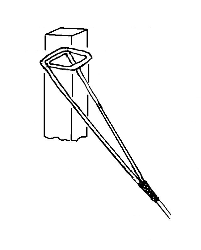
I have been working on the fore course yard (spreader yard) and the fore topsail yard. For this I had to determine the position and types of rigging on each for rigging them to the fore mast before I install them. This lead to some problems trying to determine where all of the rigging should go on the fore mast, especially at the top. This sketch shows how much of this rigging is crowded around the fore top. I count 23 blocks in the drawing on 30 lines, and there are 10 more lines that come down from the topsail and yard above and pass through fairleads on the aft crosstree on the way to the base of the mast! The fore stay, jib stay and preventer created problems. These lines are normally shown looping around the lower mast just above the bolster on the trestletrees, lying over the shrouds. The lines would then lead down over the cheeks and would be seized together (or moused) in front of the mast. But because of the rake of the mast this would cause the forestay to rest on the fore course yard or very close to it. The jib stay and preventer would run in a similar way and could interfere with the truss tackle below the trestletrees. It was all very crowded around the fore course yard. I looked through Chapelle's "The Baltimore Clipper" and Marquardt's "The Global Schooner" to see if there were any examples where these stays were routed another way. I found six examples dating back into the late 1700s where the stays were looped behind the lower mast higher up in the head, and even looped over the top cap. (Millbrook 1797, Flying Fish 1806, Experiment 1812, Hornet 1831, Santiago 1833 and Vigilant 1848) There were cleats attached to the aft side of the mast to support the stays, and in some cases lashings around the masts. I plan to loop the stays around the mast below the mast cap, just above the metal band for the main top stay. This way the fore stay will come down along the sides of the trestle trees behind the fore crosstree and will then be siezed together some distance in front of the fore course yard. The jib stay and preventer will come down between the trestletrees in front of the fore crosstree. The stays will not interfere with the other rigging in this area. There were several other rigging questions that I needed to answer before proceeding. The sling that supports the fore course yard loops around the top of the lower mast and lays on the shrouds. After studying several examples I decided to use the configuration shown. It is made up of two parts. The upper loop has a thimble seized in an eye above the spar. From this the two legs go up on either side of the cheeks. The shorter starboard leg has an eye spliced alongside the mast. The longer port leg wraps around behind the mast and has an eye spliced where it meets the starboard leg. These eyes are lashed together to complete the loop around the mast. The lower part is a loop with a thimble spliced into an eye at the upper part. The lower part is looped around the spar from the front and the bight brought up behind. The eye and thimble are pulled through the bight to close the loop. The loop passes between the sling cleats on the fore side of the yard near the center. The eyes of the two parts are lashed together to support the spar. This configuration can be rigged in two parts, one around the mast at the top and one around the spar. Then when the spar is hoisted up into place the parts can be lashed together. The fore gaff throat halliard has a similar strap to the upper part of the yard sling. It loops around the lower mast and is positioned over the yard sling with the eye and thimble hanging behind the mast and the two eyes lashed together on the port side. The upper double block of the halliard tackle has a hook that passes through the thimble on the strap. The lower block of the tackle has a hook that catches a ring bolt on the upper side of the boom jaws. The fore course yard trusses are somewhat speculative. Their function is to pull the yard back against the mast so it cannot swing while the vessel is rolling and pitching. When the yard is to be repositioned the trusses are loosened. Many smaller vessels do not have trusses so it was a question whether they are necessary. They certainly do add to the clutter in the mast hounds area. But while I was designing the fore course yard I discovered that the topsail schooners had a yard equal to or greater than for the square rigged ships. Both Fincham and Rankine (naval designers of the late 1700s and early 1800s) used formulas that produced extra long and heavy yards. So I decided that the trusses might be necessary - and they will be interesting to rig!. There are two ropes with eyes and thimbles at each end. One eye is laid on top of the yard with the rope looped behind and below the yard and back up and over. The parts are spliced together close to the eye on top of the yard. The other rope is looped around the yard in the same way. The loops are at the center of the yard between the sling cleats, on each side of the yard sling. Now the loose ends of the ropes are passed around behind the mast and then through the eye of the other rope and lead upwards. The second eye in each rope connects to the hook on a single sheave block. This is part of a luff tackle with the upper double block hooked to an eyebolt on the bottom of the trestletree. The fall of the tackle leads down and is belayed at the base of the mast. When the falls are tightened the tackle pulls the slack out of the truss loops to pull the yard against the mast. Prior to about 1810 the ropes led down to the deck after passing through the eyes (which were on the aft side of the yard). The luff tackle was hooked to eye bolts on deck. But after 1810 the truss tackle was rearranged as shown here. There were other truss arrangements, including one that used a single rope. That might be more appropriate on a small vessel.

-
I have the same problem. I started a kit in the mid 1980s. The plans were incomprehensible (for me). What few books I had said a lot about history and nothing about how ships were built. So I constructed the stern the way more modern vessels are built. This has bothered me, but I really don't care enough to try and "fix" it. I have discovered other errors in the build, and fixed a few. But I am kitbashing it into a hypothetical vessel anyway (everything from the deck up is scratch built). For me it is a learning experience, and I am enjoying the research to learn how these ships were built. Maybe my next build will be "perfect" but for now this imperfect one is good enough. So how much do you care if your Bellona model isn't perfect?
-
While "wood" might not change much with time, some plywood will. I have scraps left over from kits in '60s and '70s (50-60 years old) and some of the plywood has become unlaminated, or the glue has deteriorated enough that you can separate the layers with your fingers. This really isn't a problem in the finished kit build because the plywood is glued to lots of other pieces, and is inside the finished model. But for an unfinished kit having the plywood disintegrate while you are trying to build it would be very annoying. I have some unbuilt kits from the '80s and '90s (30-40 years) and the plywood is still good. The fittings are much better than the parts from the older kits. But the blocks still leave a lot to be desired. I can't say anything about the newer kits because I am into scratch building now.
-
Bulkhead sanding advice
Dr PR replied to Jameskilroy's topic in Building, Framing, Planking and plating a ships hull and deck
James, Fairing the edges of the bulkheads is tricky. You can quickly get into a situation where you take too much off of one, and then remove some from the neighboring pieces to smooth the curve of planks. Then you discover you took off too much from one of those later bulkheads so you need to tale some off of another ... Eventually you realize that you have removed too much from them all and the hull is too narrow and the curves all wrong! I try to leave a bit of the original bulkhead edge so I don't remove too much. It paint the edge or mark it with a. soft lead pencil. While fairing the bulkheads remove as much as necessary to shape it but leave a thin bit of the paint/pencil along the high edge. Sometimes the kit bulkheads really aren't sized properly, or they aren't positioned correctly on the keel so one side is "high" and the other low. Just add a strip of wood to the low side and fair it until a plank curves over it correctly (a smooth curve). For the high side sand it down until a plank curves over it without a high spot. One other tip. Some kits do not have enough bulkheads, especially midships. The planking will tend to flatten between widely spaced bulkheads, with an apparent high spot when the planks fit to the bulkhead. You can always create another bulkhead to fit in the gap and fair it to fit the curve along the hull. Some people just fill in all the spaces between bulkheads with scrap wood and fair the whole thing like a solid wood hull. Don't sweat it if you end up with what appears to be a cobbled up set of bulkheads. The planking will cover it. But if the bulkheads aren't faired correctly the planking will have bumps and hollows that are very apparent! -
Allan, I have spent quite a bit of time trying to find reliable period references for the colors on ships - with little luck. There are some general guidelines for British and French vessels, mainly derived from period paintings. But the exact colors probably will never be known. Artists mixed their own paints and they were, therefore, their renditions of the colors, not what was actually on the vessel. And colors change with time (fading, oxidizing, etc.). In many cases the actual colors would have been up to the Captain's whim and what paints/pigments could be had on a particular day. In other words, the colors could have been anything. And the anti-fouling mixtures probably varied with each vessel. It would depend upon the type and age of the tallow, what solvents were used and how it was all mixed and applied. Again, just about anything. In my opinion, you could use any off-white, slightly yellowish mixture and be just as accurate as anyone else could come up with. So don't sweat the small stuff. Make it appear pleasing to your own eye, and let the beholders form their own opinions. Opinions are like noses - everyone has one. And none will be better than yours (except mine, of course).
-
Craft stores carry stainless steel multi-strand beading and jewelry wire. I have some 3 strand and 7 strand 0.012 inch (0.30 mm) and 7 strand 0.015 inch (0.38 mm) and 0.018 inch (0.45 mm) wire. At 1:87 scale these would be: 1:87 diameter 1:1 diameter 0.012 "/0.30 mm 1.0"/26.1 mm 0.015 "/0.38 mm 1.3"/33.1 mm 0.018 "/0.46 mm 1.6"/40.0 mm Pros: It looks real and is very durable. Cons: It is OK for straight runs, but it is VERY springy and I wouldn't want to try it with blocks or winch drums.
-
There are seven species of hawthorn in the northwest (Oregon): https://oregonflora.org/taxa/search.php?search=hawthorn English hawthorn is the most common - it is a nuisance weed. It has pretty flowers in the spring and lots of red berries in the fall - that the birds spread everywhere. I don't know if the wood is any good for modeling, but there is one in my neighbor's yard that I would happily cut down to see. None of the seven hawthorns is known as "fire thorn," at least today by modern botanists. Common names are not reliable. They are often applied to several different species. Apparently "firethorn" is a totally unrelated species to hawthorns: https://en.wikipedia.org/wiki/Pyracantha We have these here also, and they too are a nuisance weed.
-
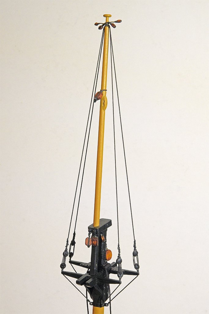
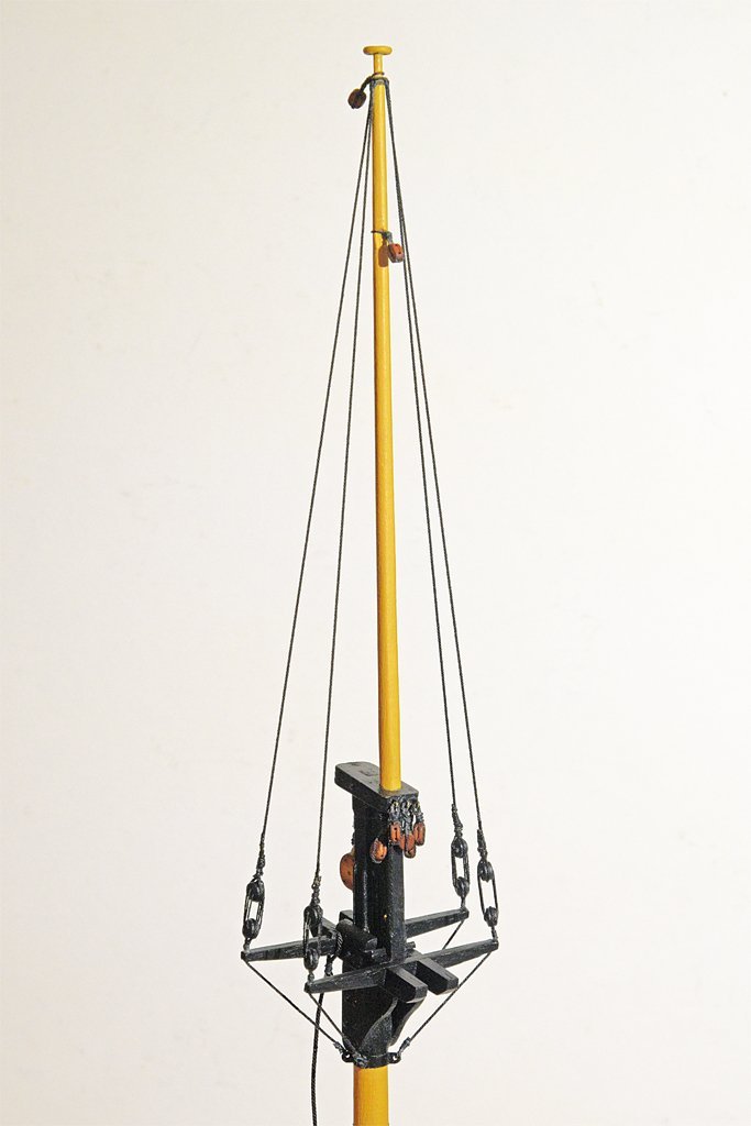
I have only a few small details to report. I am preparing the masts for installation into the hull. For this I want to be sure I get all the necessary rigging points on the masts while they are still free to work with on the table. On the main topmast (left below) I added the topmast shrouds and blocks for the main gaff topsail halliard near the truck and lower down the block for the main topmast staysail halliard. The main topmast stay will attach directly above the strap for the block. On the main top cap are blocks for the fore topsail yard braces, main top staysail sheet and fore course yard braces, and on the aft side of the mast itself is a block for the main gaff peak halliard. The fore topmast (above right) is a bit more complex because of the square topsail rigging. Above the topmast stays near the truck are blocks port and starboard for the topsail yard lifts and the topsail buntlines. Below this is a block for the flying jib halliard. The flying jib stay will attach above the block strap. There is also a sheave for the topsail yard halliard on the port side. On the mast cap are blocks for the fore course yard lift and buntlines (port and starboard). On the aft side of the mast top are attachments for the main topmast stay, main topmast staysail downhaul block, and the peak halliard block. I had a choice for placing the sheave for the topsail yard halliard. One method would be to install the sheave in a pocket cut into the topmast. I have done this is several other places, but these were near the ends of the jib boom and main boom. In these positions the spar will not be stressed significantly. But cutting through the topmast below the attachment points for the shrouds and stays would create a weak point where the mast might be stressed. The option is to attach a sheave to the side of the mast with a cheek block. Here you can see the cheek block on the left side of the mast (the halliard belays on the port side of the fife rail at the base of the mast). Above it are thumb cleats to support the flying jib halliard block and the flying jib stay. It looks to me as if the flying jib halliard block is a bit too close to the mast. I may redo this to give it a long strap (strop). In this instance I have turned an eye into the strap but I think this is unnecessary. Looking at several references I see it was common for the standing part of the tackle to simply loop between the strap and the block. Lever says an eye in the standing part may be attached to the strap on the block with a short piece of rope. It will be simpler and neater to just splice an eye around the strap on the end of the standing part of the halliard.
-
Neptune, I thought this ship looked familiar. Good to see it being finished! The plumbing, cables and walkway railing work is especially nice.
-
If you don't already have it, Harold Underhill's "Masting and Rigging the Clipper Ship and Ocean Carrier" is an indispensable reference for clippers. He describes everything in detail, with hundreds of illustrations and full page plates, and appendices telling how to calculate the sizes of everything. The book has the most inclusive index I have seen, with page numbers for every part of the rigging. It is a joy to read and learn about ships of the late 19th and early 20th centuries. I'll be watching this one to see how it develops!
- 124 replies
-
- 2
-
-
- Red Jacket
- Marine Model Company
- (and 2 more)
-
John, Thanks!
-
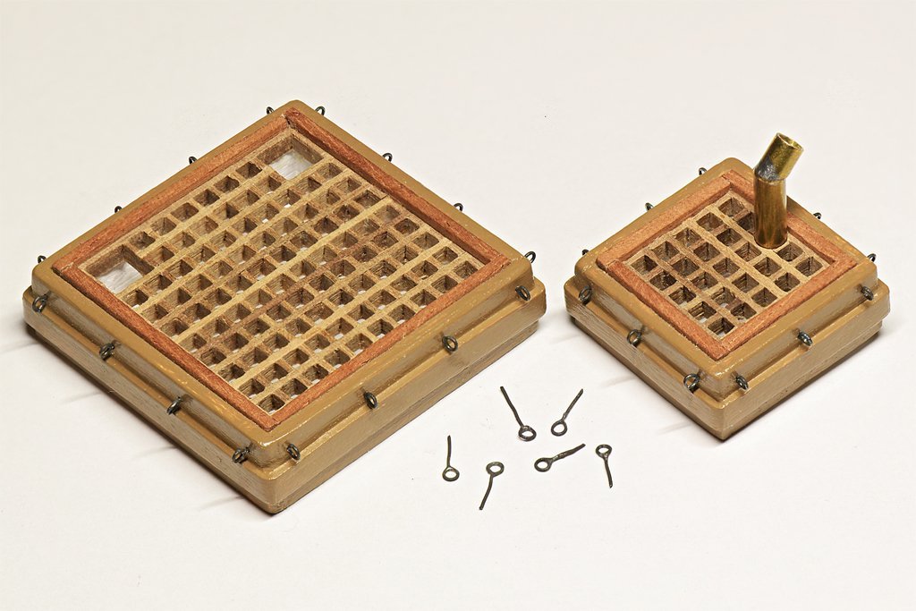
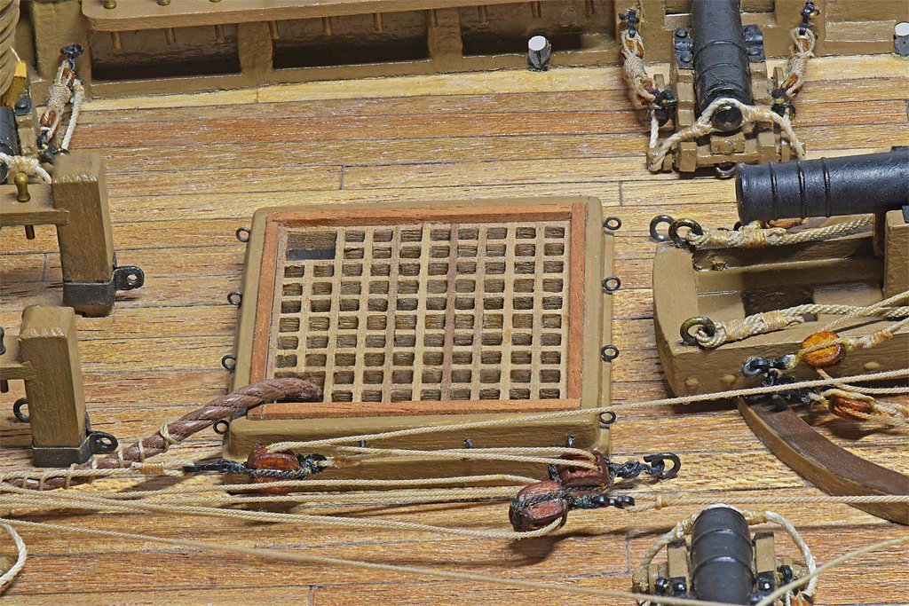
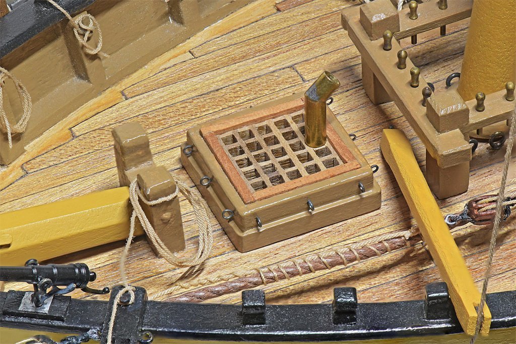
Here is another small detail. Two hatches have gratings, and the books say this was common on warships (merchantmen usually had solid hatch covers). They had to have a way to cover these hatches in heavy seas. On mid-20th century US Navy ships we had small metal hooks called "lady fingers" welded in places where we needed to secure tarps and such. However, I have never seen these mentioned for 19th century ships. I looked at a number of references and a couple suggested there were eye bolts around the hatch above the coaming that canvas tarps could be lashed to. On some vessels metal bars with slots to fit over the rings held the canvas down, and wooden pegs were driven into the rings to force the bars tight against the canvas around the hatch. I spent the day making very small ring bolts. They are made of 0.012 inch (0.3 mm) brass wire with 0.025 inch (0.64 mm) holes in the rings. After the loops were soldered closed they were blackened with Brass Black. I needed 28 of these ring bolts and made 40. While handling them for soldering five disappeared into the void (12.5%). Another broke while I was inserting it into a 0.013 inch (0.33 mm) hole in the hatch. This was a significantly worse attrition rate than any I have had in past production of quantities of small objects, probably because these things were much smaller than other parts on the model. But the real culprit was a pair of tweezers with tips that can suddenly twist to the side, launching parts into orbit. I need new tweezers! Here are photos of the hatches in place on the model. This is the last detail on my list for the deck fittings before I start working on the rigging.
-
Kieth, I'm really glad to hear you are recovering well. My eye doctor says cataract surgery is in my future in about 10 years. Last year I had growths called pterygiums removed from both eyes (too much UV exposure from hiking) - six months apart. They cut out chunks 1/4 inch (5 mm) diameter from the eyes and I never had any discomfort! I took some ibuprophen the evening after the surgeries just in case, but it wasn't needed. Everything mostly healed up in two weeks, and my eyesight was improved greatly. How can they cut on the eye like that without causing discomfort?
-
One user on the Forum cautioned about steel wool. It can leave tiny pieces embedded in wood that will eventually rust. So be sure to clean thoroughly after using it. I love #0000 steel wool for producing a fine satin finish.
-
I grew up in Hot Springs, Arkansas, and a few miles east of there is Bauxite, Arkansas. It is a very geologically interesting region with many different minerals in what was once the roots of an ancient mountain chain that has eroded flat by now. I have been told that for much of the early 1900s this was the only source of bauxite/aluminum in North America. We had three lakes and hydroelectric generating stations around Hot Springs to power the aluminum plants at Bauxite. ALCOA and Reynolds both had aluminum mills there. When in high school I went to one of the plants for a meeting. It was about a mile square and extended many stories high. We drove into this machine for some distance and went to the meeting in a building embedded deep into the plant. It was quite an experience. I think the bauxite has played out now, and only a series of huge craters remain, filled with water, with housing developments around them.
-
Valeriy, I seem to recall that after aluminum was discovered in 1825 the Czar of Russia had a helmet made of aluminum that contained almost all of the purified metal on Earth. Aluminum was valued at many times the cost of gold and the helmet was said to be one of the most valuable things on Earth! At first small specimens cost about US$160 per pound, Then new techniques for separating the metal were discovered. In 1855 Aluminum cost US$90 per pound. Then in the late 1880s mass production of aluminum began and the cost dropped to US$2 per pound. Then the modern electrolytic separation method was developed in 1889 and the cost per pound dropped to US$0.20, and was cheap enough to use in ship building. The value went from the most valuable substance on Earth to a fraction of a dollar in a little over half a century. Now that is deflation!
-
John, Thanks. I could have omitted the swivel guns but I liked the guns on the Lady Washington. When the Syren parts turned out to be the right type and size I couldn't resist.
-
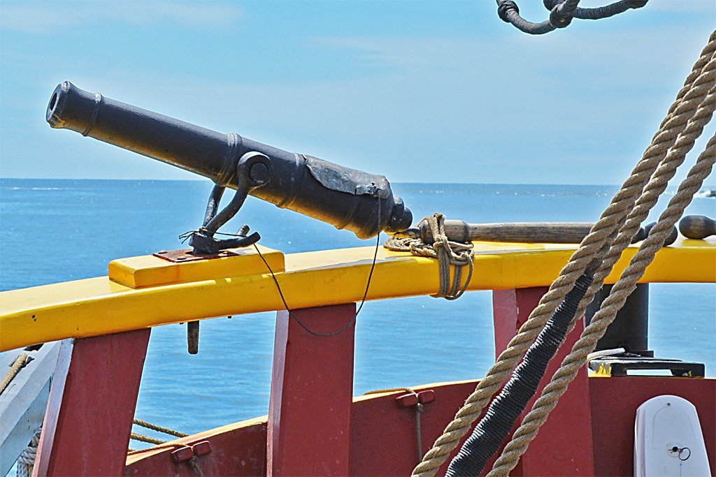
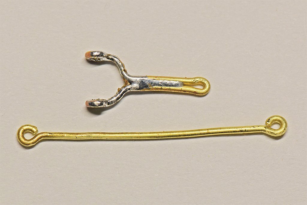
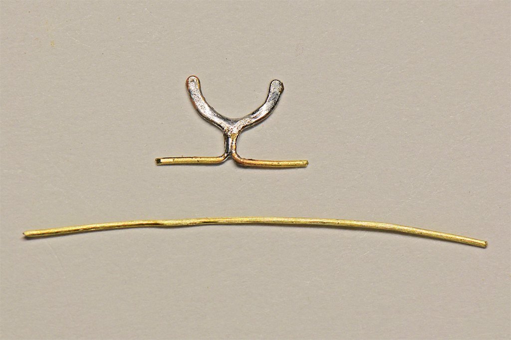
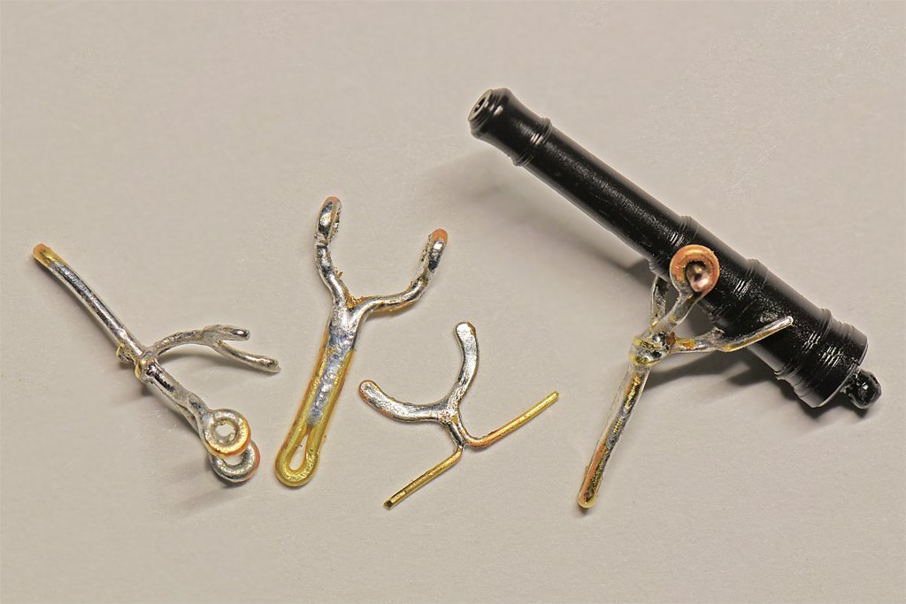
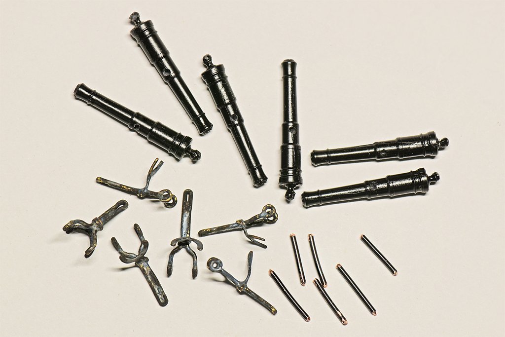
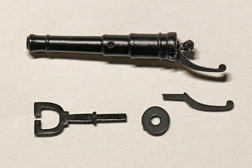
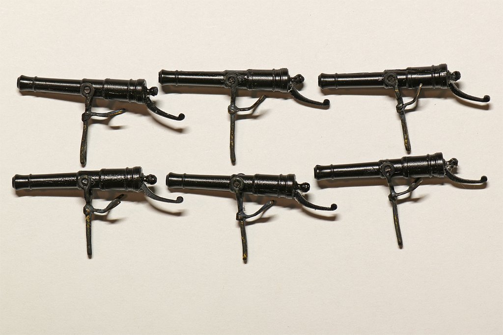
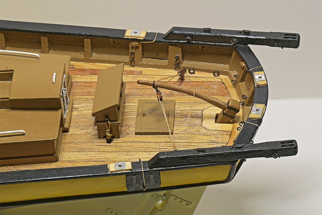
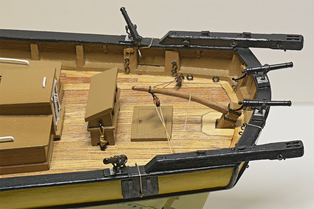
Another detail to be added before starting rigging was swivel guns. Some references say some early 1800s schooners carried them. So I thought I should add a few at the bow and stern. I ordered a package of "Resin Swivel Guns (13/16") w/handle and Yoke" from Syren Ship Model Company. The package included six molded resin guns with yokes and round plates for mounting them. It also included a handle for the back of the guns. However, you have to drill a hole in the rear end of the gun below the cascobel to mount the handle (not a problem). I looked in Chapelle's "The History of the American Sailing Navy" (1949) and on page 89 he has drawings of swivel guns just like the Syren product. Furthermore, the dimensions of the Syren guns are perfect for a 1:48 scale 1 1/2" bore 1/2 pound shot swivel gun like those used in the American Navy! The Syren mounting parts are OK, but I wanted to replicate something like the yoke on the swivel guns on the modern Lady Washington replica. These swivel guns look exactly like Chapelle's drawings and have the "U" shaped rest to hold the gun in position for loading. They also have a wooden handle attached to the rear end, and Chapelle says this was common, along with several other styles of handles. I thought about adding a wooden handle to the Syren parts, but I like the handles supplied with the guns and decided to use them. OK, how was I going to fashion the yoke and the "U" shaped fitting? Since I don't have a machine shop to make these pieces it would have to be pretty simple. I decided to use brass wire. The yoke was made from 0.025 inch (0.64 mm) wire as shown in the picture below left. After making the small loops for the gun's trunnions at each end of the wire I soldered the loops closed. Then the wire was folded double and the upper "U" shape bent to the proper width. Then the doubled part was soldered. These were cleaned up later with a file to remove excess solder. The "U" shaped rest was made from 0.012 inch (0.3 mm) brass wire as shown in the picture above right. The wire was bent around a 0.125 inch (3.2 mm) drill bit (the cannon is 0.115" (2.9 mm) where it fits into the rest). Then it was folded back double to finish the "U" and the support arm was created as shown. The wire ends of the rest piece were then wrapped around the shaft of the yoke and soldered in position. This was the only difficult part of the assembly. The two wire ends of the rest needed to wrap tightly around the shaft of the yoke, and the support arm of the rest should be aligned with the shaft of the yoke so the "U" was positioned correctly for the gun to fit into. But as I added solder to fasten the rest in place things wanted to move around. Eventually I worked out a way to keep everything in place while I soldered it. You can see how things fit to the gun on the right, but the rest arm should be a bit lower and horizontal, and the "U" bent up a bit to cradle the gun. After a while I had six yoke assemblies, six trunnion pins and the six guns. I drilled holes through the guns for the trunnion pins. The brass parts were blackened with Birchwood Casey Brass Black. After the guns were assembled I clipped off the excess length of the trunnion pins and touched up with a bit of flat black enamel. I decided to duplicate the arrangement on the Lady Washington and add thin wooden blocks to the rails where the guns would be mounted, and a thin metal plate for support. After these were glued in place and painted the swivel guns were installed.
- 421 replies
-
- 11
-
-

-
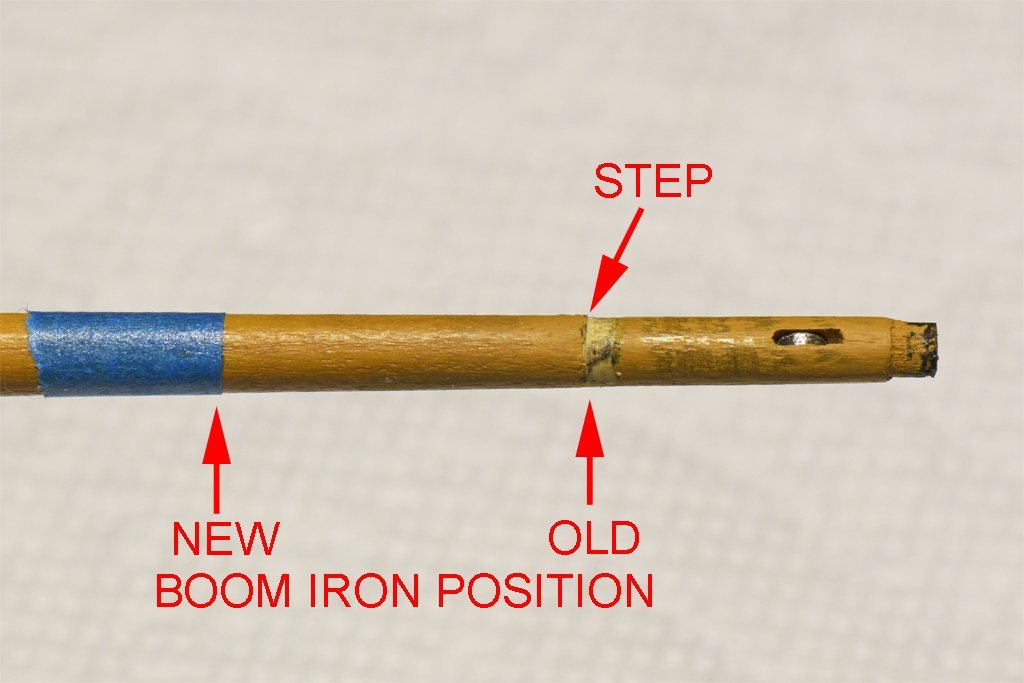
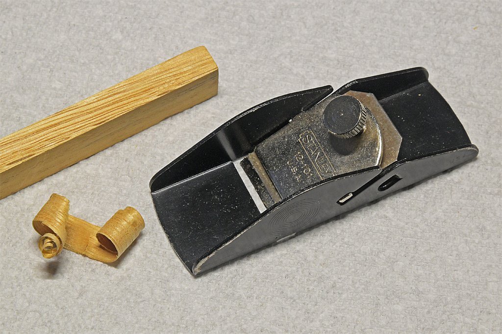
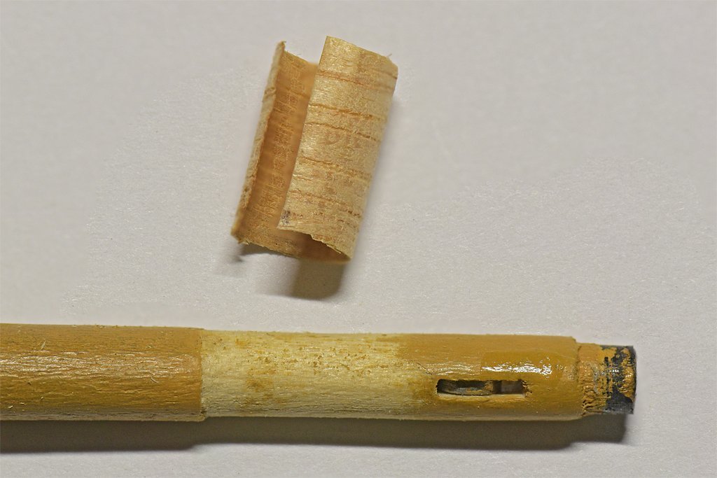
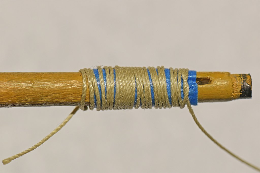
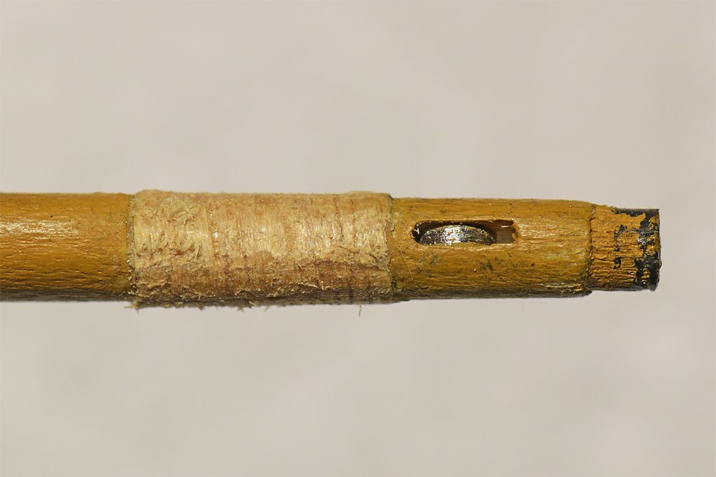
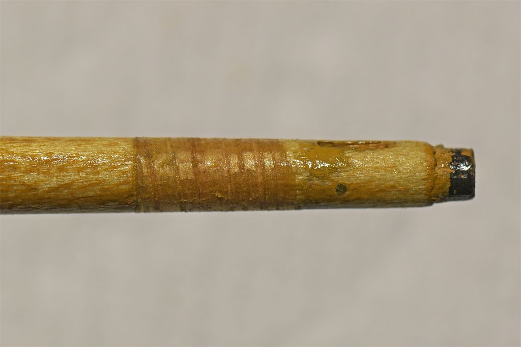
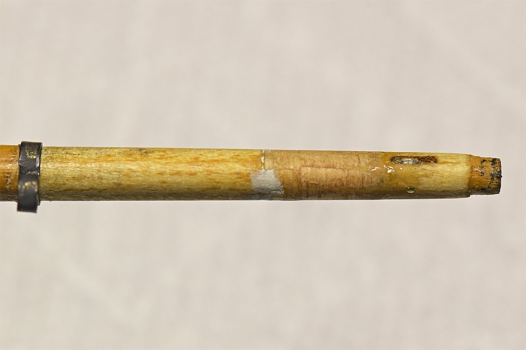
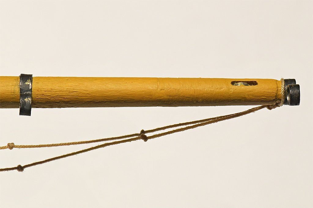
I had to fix the error in the ringtail boom iron position! I put the second boom iron about 1/5 of the boom length from the boom iron on the end of the boom, and the separation should be about 1/3 the boom length. I have several hours work in the existing boom, so I wanted to repair it if I could and reposition the forward boom iron. This photo shows where the original boom iron was positioned (old), and where it should have been placed (new). The original boom iron was a bit undersized so I filed a reduced diameter area where it was located. Some wood was also removed closer to the end of the boom so the iron would slip into position. Now I needed to build up the area (step) where the wood was removed. The solution (I hoped) would be to use my old Stanley miniature plane to shave a thin strip off a square dowel and use this as filler to be glued around the boom in the repair area. I had no idea if this would work but it seemed a better option that starting over on a new boom. The wood shaving was 0.009 inch (0.22 mm) thick. I wrapped it around the boom one turn, trimming the ends to overlap slightly. I used a liberal amount of Sig-Bond aliphatic resin to glue the shaving in place. I wrapped the shaving around the boom as tightly as possible - but of course the shaving wanted to spring back out. I wrapped some blue painter's masking tape around the shaving to hold the shaving tight around the boom. Then just to be sure I wrapped some carpet/button thread tightly around the tape to be sure the whole thing was compressed. After about eight hours I removed the tape and thread and started filing and sanding the wood shaving into shape. I forgot to take a photo before starting, so the picture on the right above is after a bit of reworking to shape the shaving. After sanding the shaving to shape it was coated with shellac (left). When that dried I used some Squadron White Putty to fill in some low spots (right) I also shaped the boom so the new boom iron could be added at the correct position. I should have used a more homogeneous wood for the shaving. The dowel I used had pronounced grain, and the softer light colored growth ring material sanded away faster than the darker growth rings. I sanded it carefully and with the shellac managed to get a fairly smooth surface. But this was another "learning experience." After two coats of paint, with sanding between the coats, the result looks pretty good. But just don't look too closely! There are some very slight "ripples" where the harder growth ring wood stands slightly proud. But all in all, I'll keep it. It is a lot better than starting over with a new boom! Two steps forward, one step back!