


Ab Hoving
-
Posts
544 -
Joined
-
Last visited
Content Type
Profiles
Forums
Gallery
Events
Posts posted by Ab Hoving
-
-
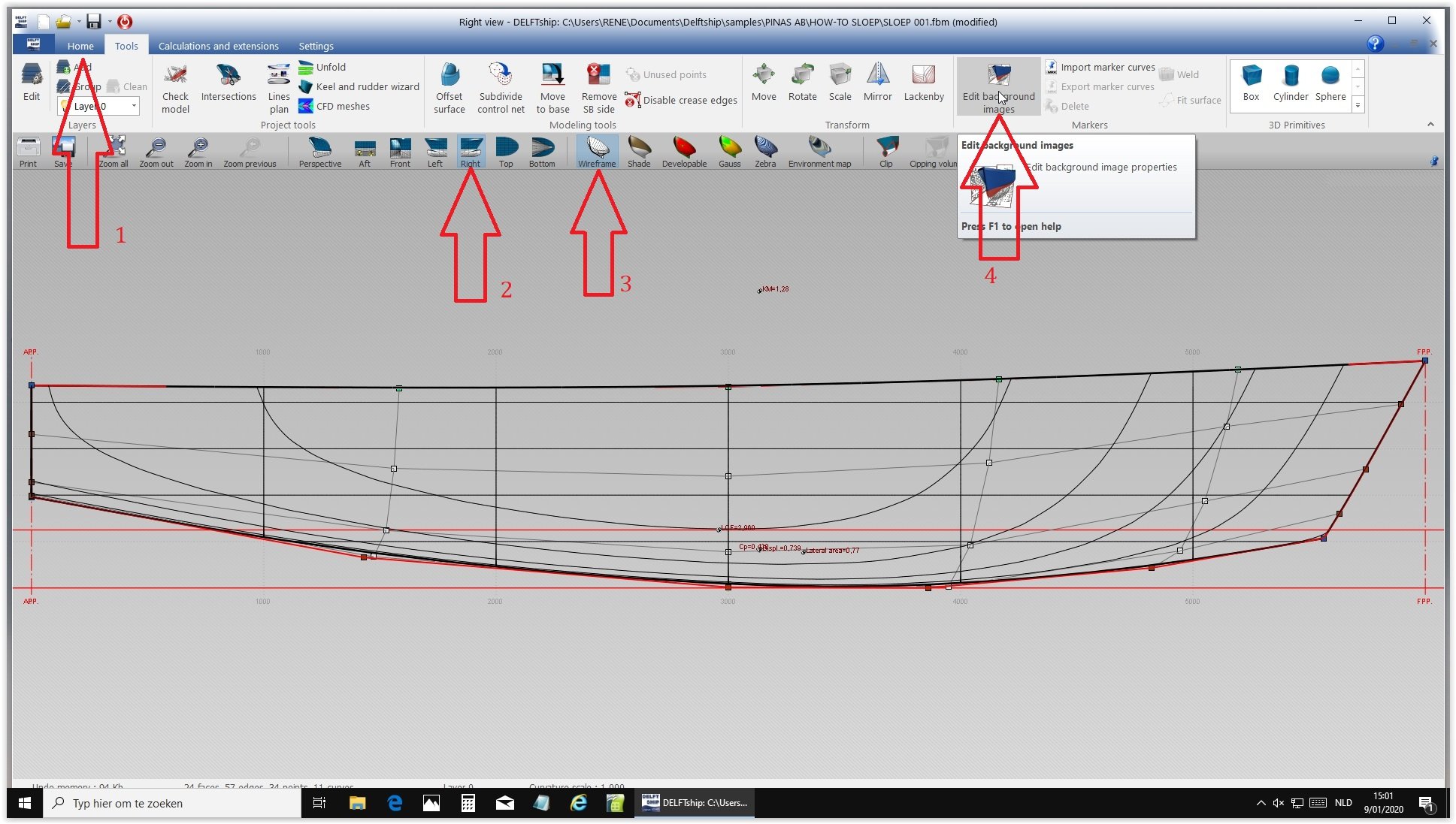
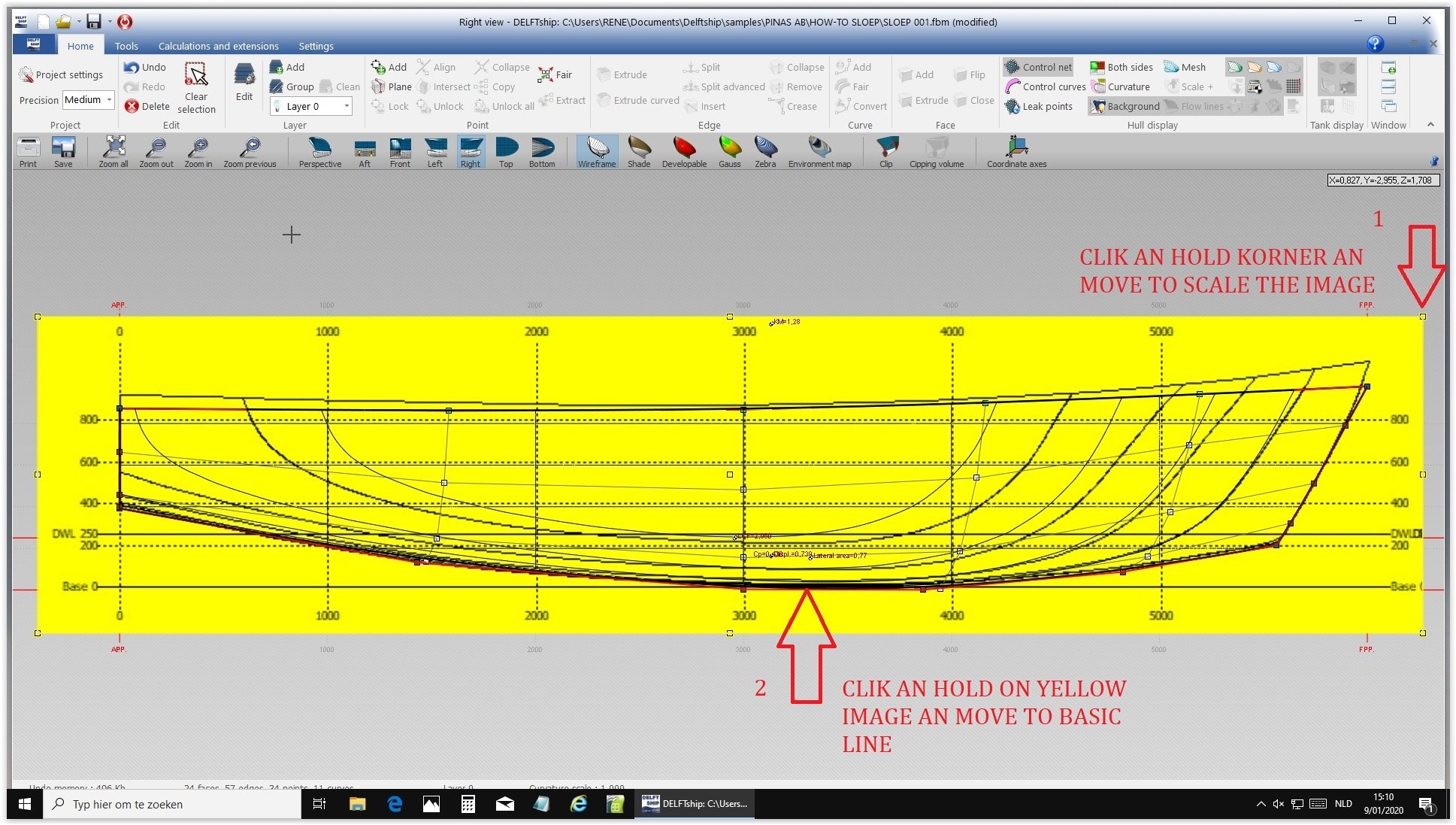
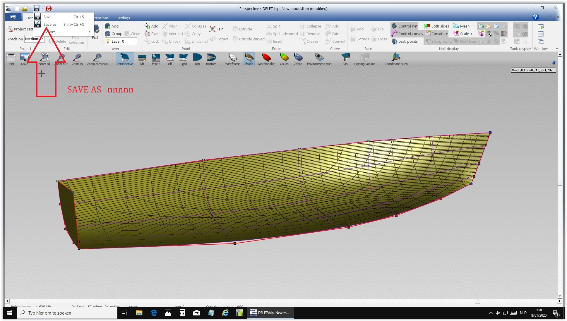
How to import the side view.
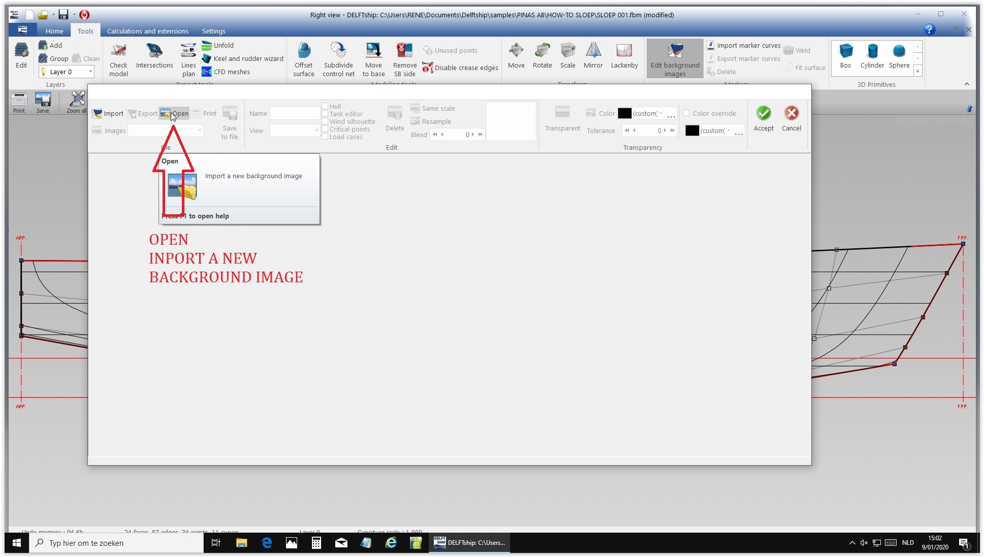
Choose side view and edit background.
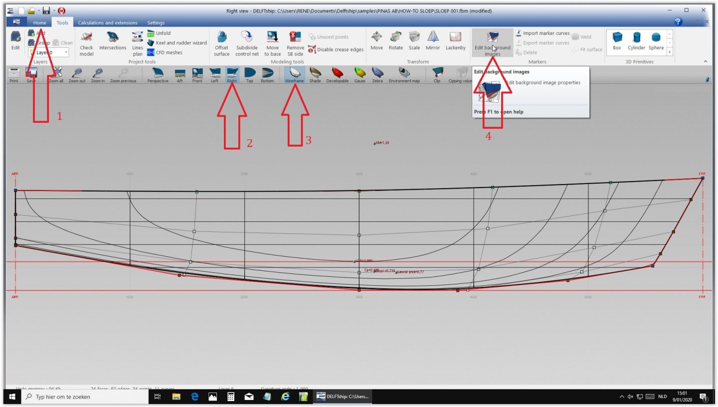
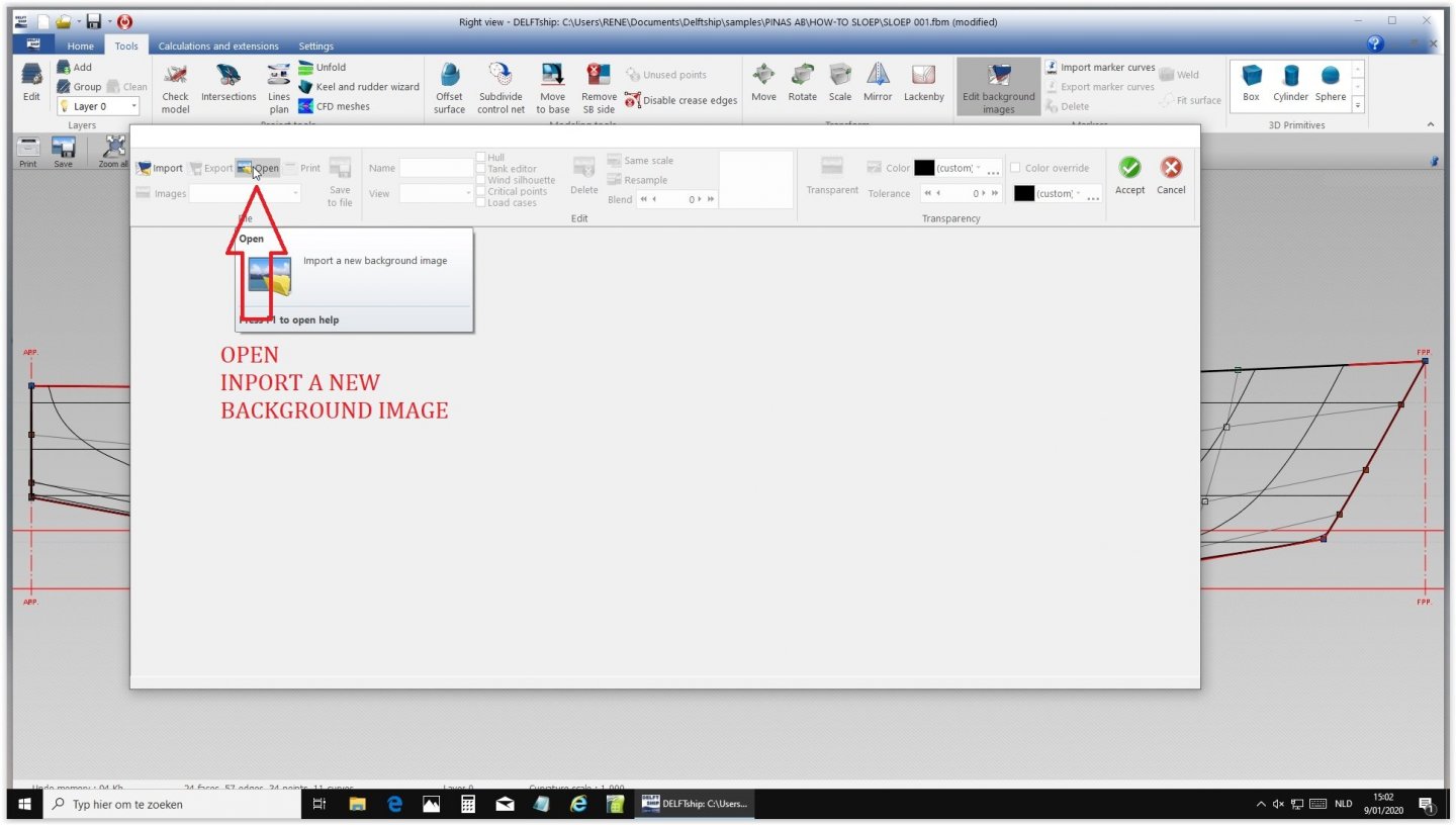
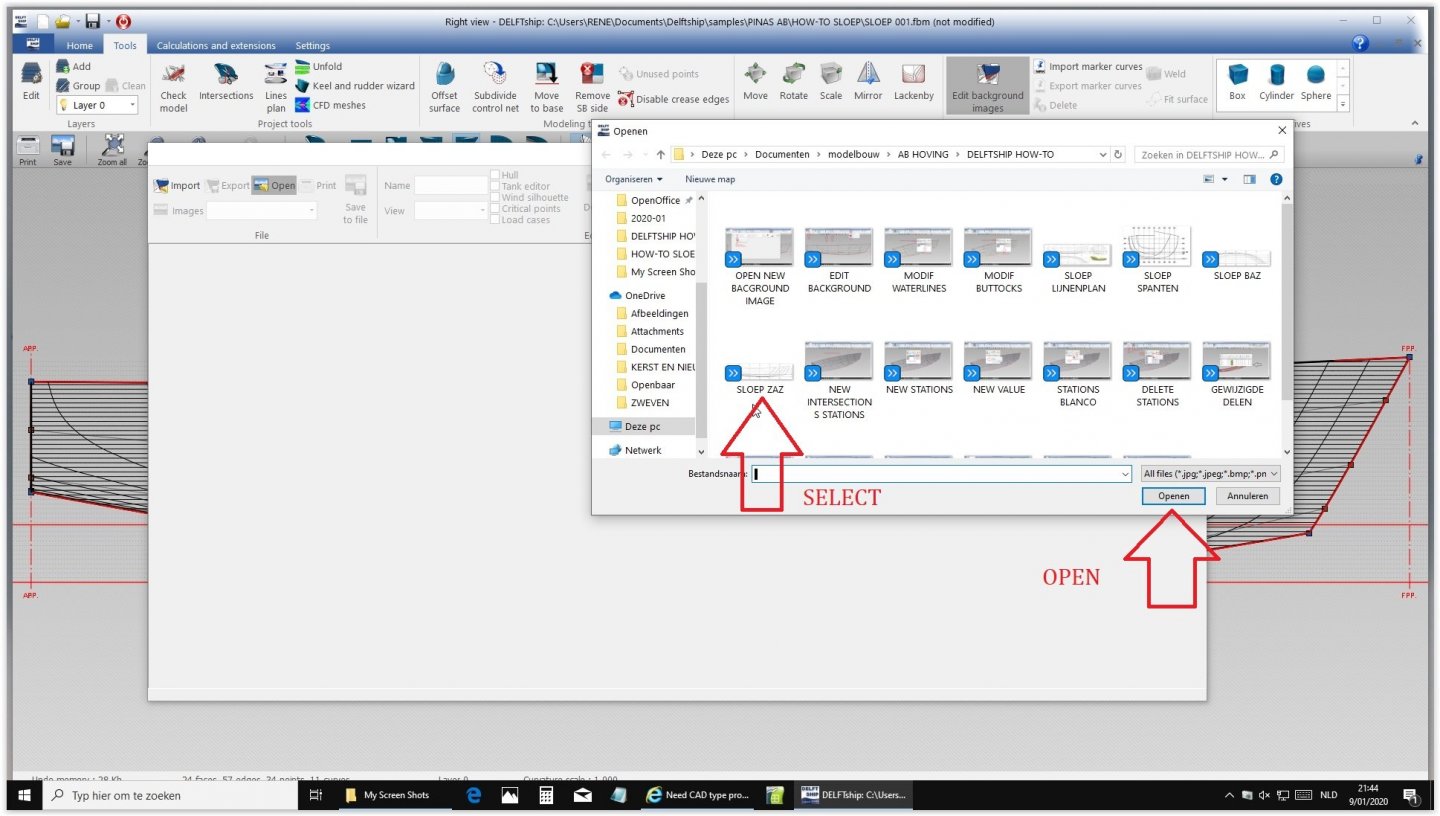
Open import background image and select ZAZ and open.
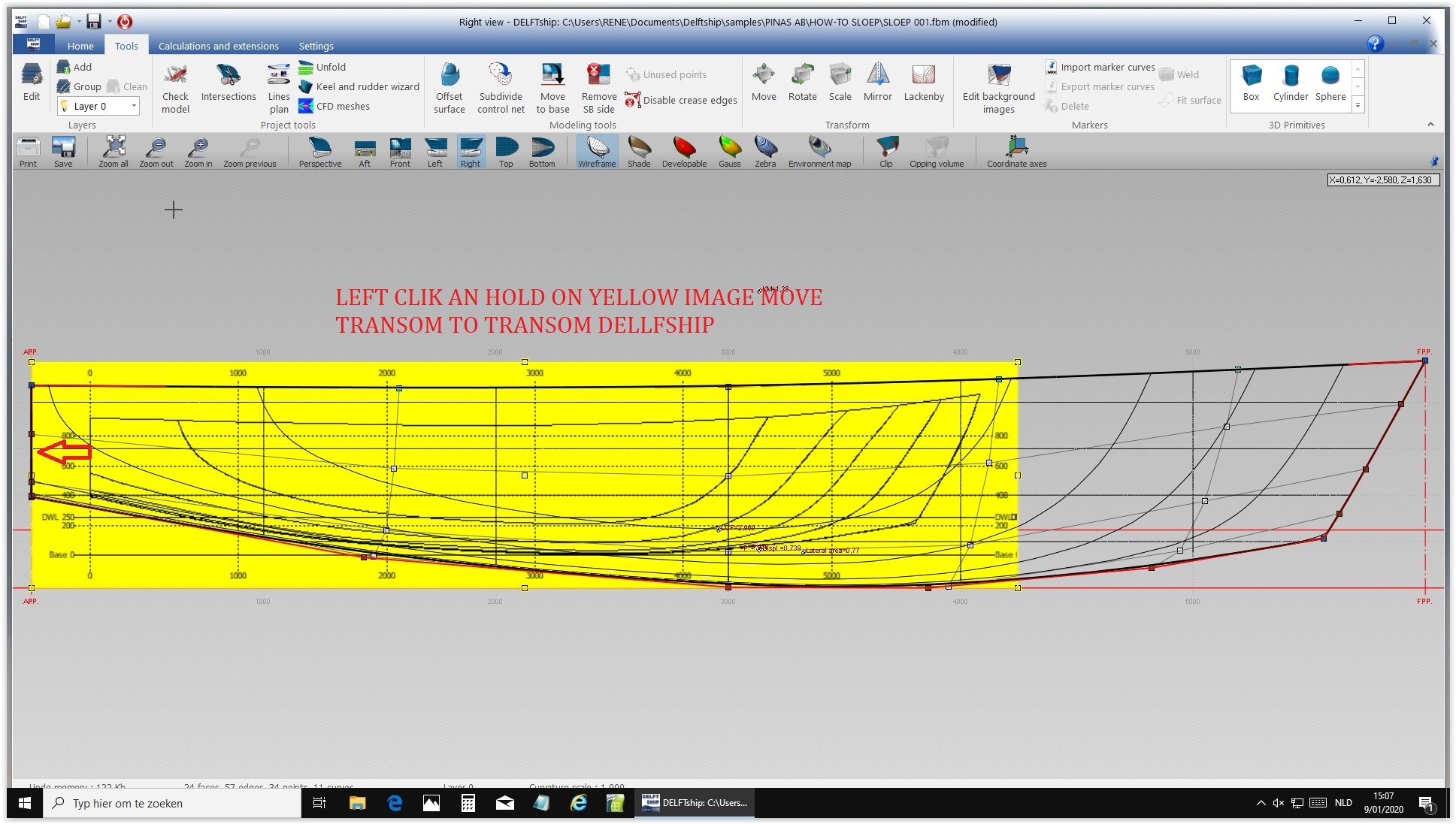
Click and hold to match the sterns

Click and hold the right top of the yellow image and stretch until both hulls match. Check and double check.

Do the same for the bottom until they match ate the bottom line.

Click on the yellow part, which turns to white.
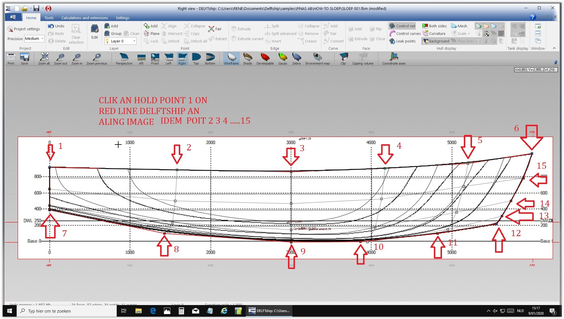
Now click and hold several points on the DELFTship hull and drag them to the new shape until they match. Make sure that in the end the fat black lines match perfectly. This takes some experience.
Now the outlines should be equal.
Next time: same procedure in top view and body plan.
-
Marcus,
Why do your four forward frames curve inwards at the top?
-
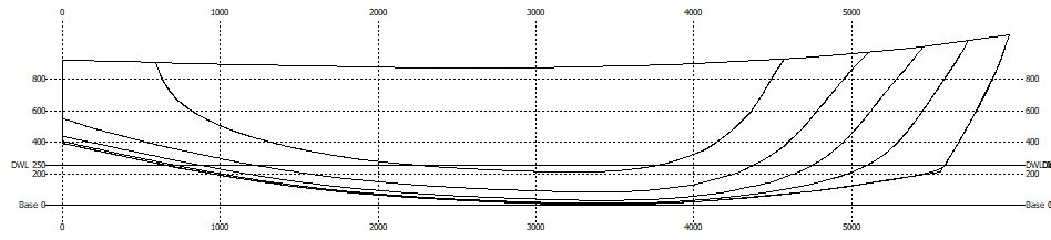
Before a lines plan can be inserted in DELFTship the elevation view, the top view and the body plan have to be separated.
As an example Rene took a lines plan of a sloop he previously made in DELFTship. The shape differs from the default DELFTship hull. Next time he will bring it into the program and show how the shape can be adjusted. Here the newly made lines plan:
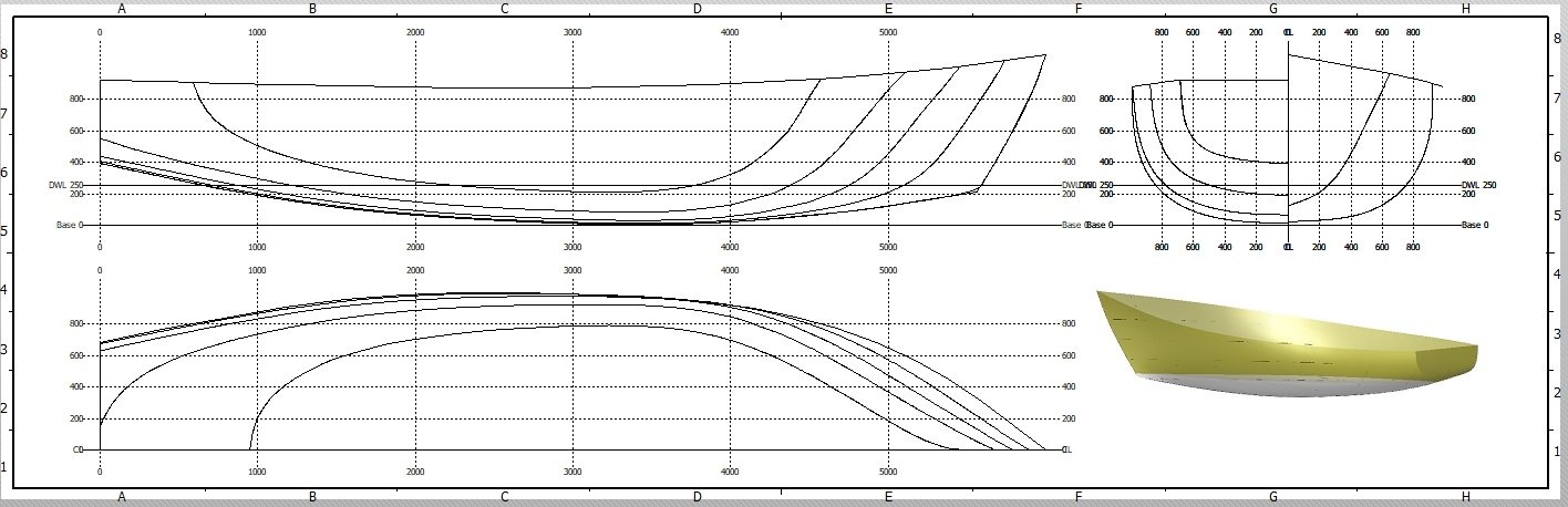
Separated into an elevation view,
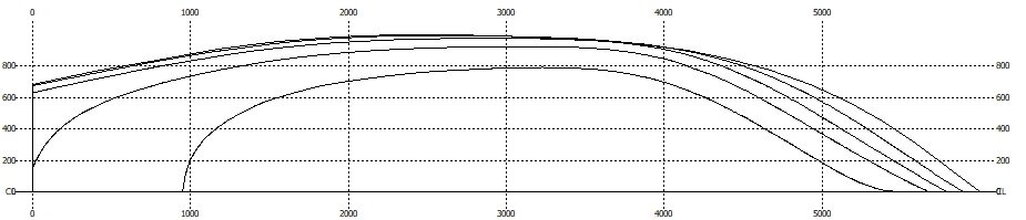
a top view
And a body plan.
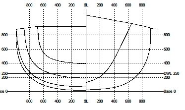
See you next time.
- bruce d and Kris Avonts
-
 2
2
-
What we are doing here is all possible in the free version.
The lines plan will follow soon. This is 'a 12 steps program' :-).
It takes several steps to insert a lines plan, we'll do one after another. If there are any questions on our way there, just scream.
The system differs a bit from other programs, which sometimes causes troubles with experienced users who worked with other systems, so stay close.
- Kris Avonts, bruce d, thibaultron and 1 other
-
4
-
No, they are not from the free version, but as far as I know that makes no difference. I will ask Rene. (We both received a free professional version by the DELFTShip company after they found out what we did with their program)
- bruce d and thibaultron
-
2
-
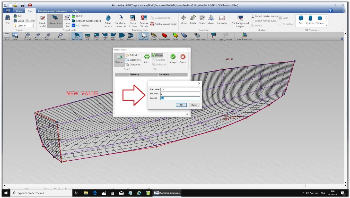
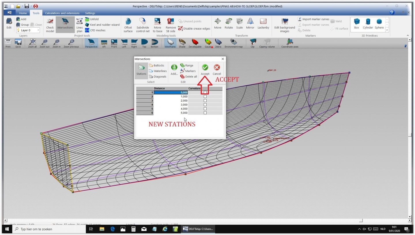
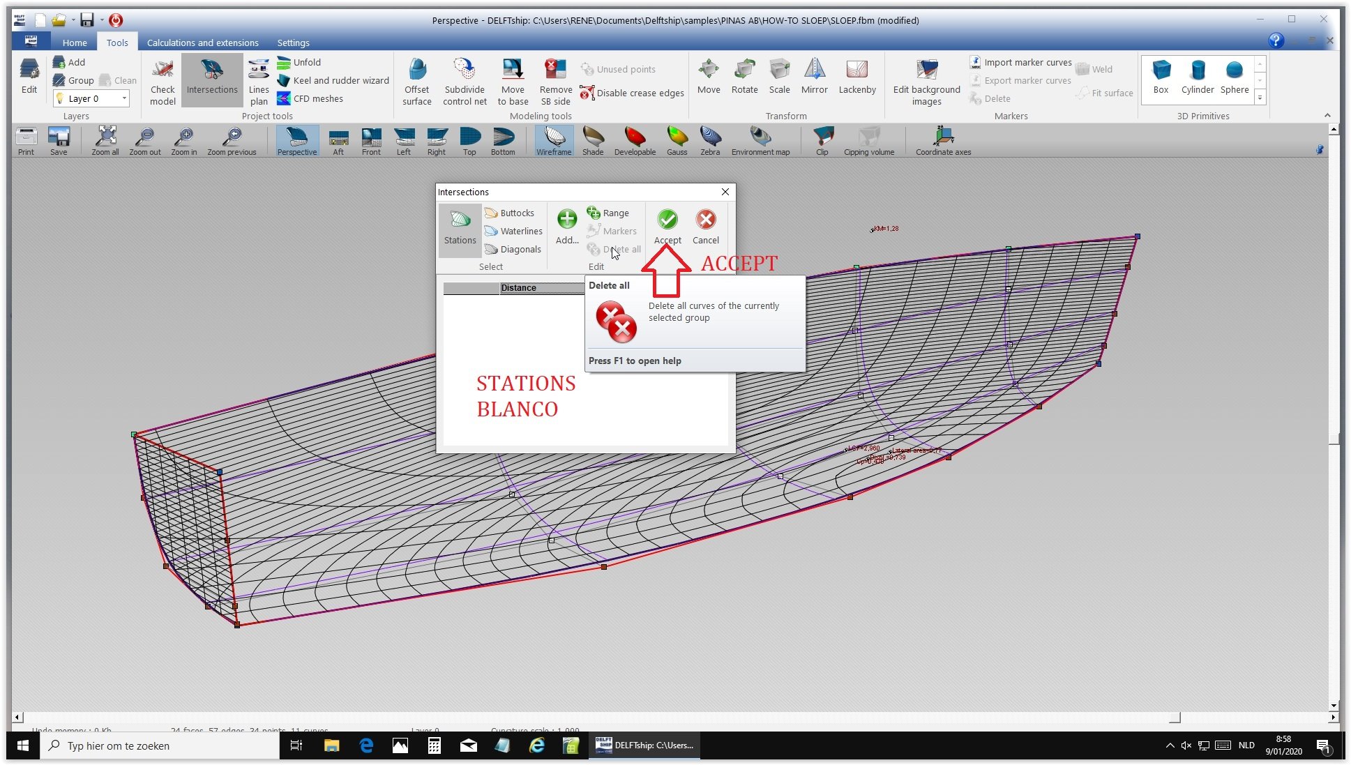
Here is the procedure to insert a lines plan.
We use a stern and 5 station frames. The fewer stations the better the fairing.
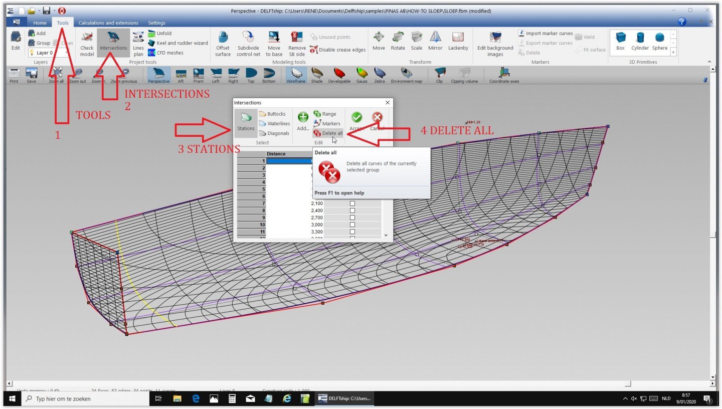
So we will remove 20 frames and insert 5 new ones.
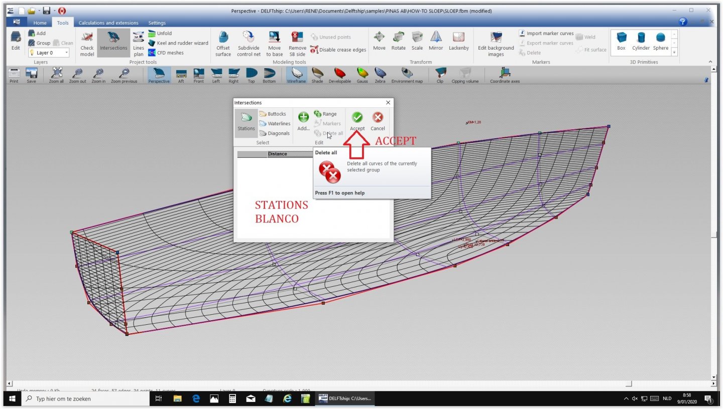
The shell has 5 frames now.
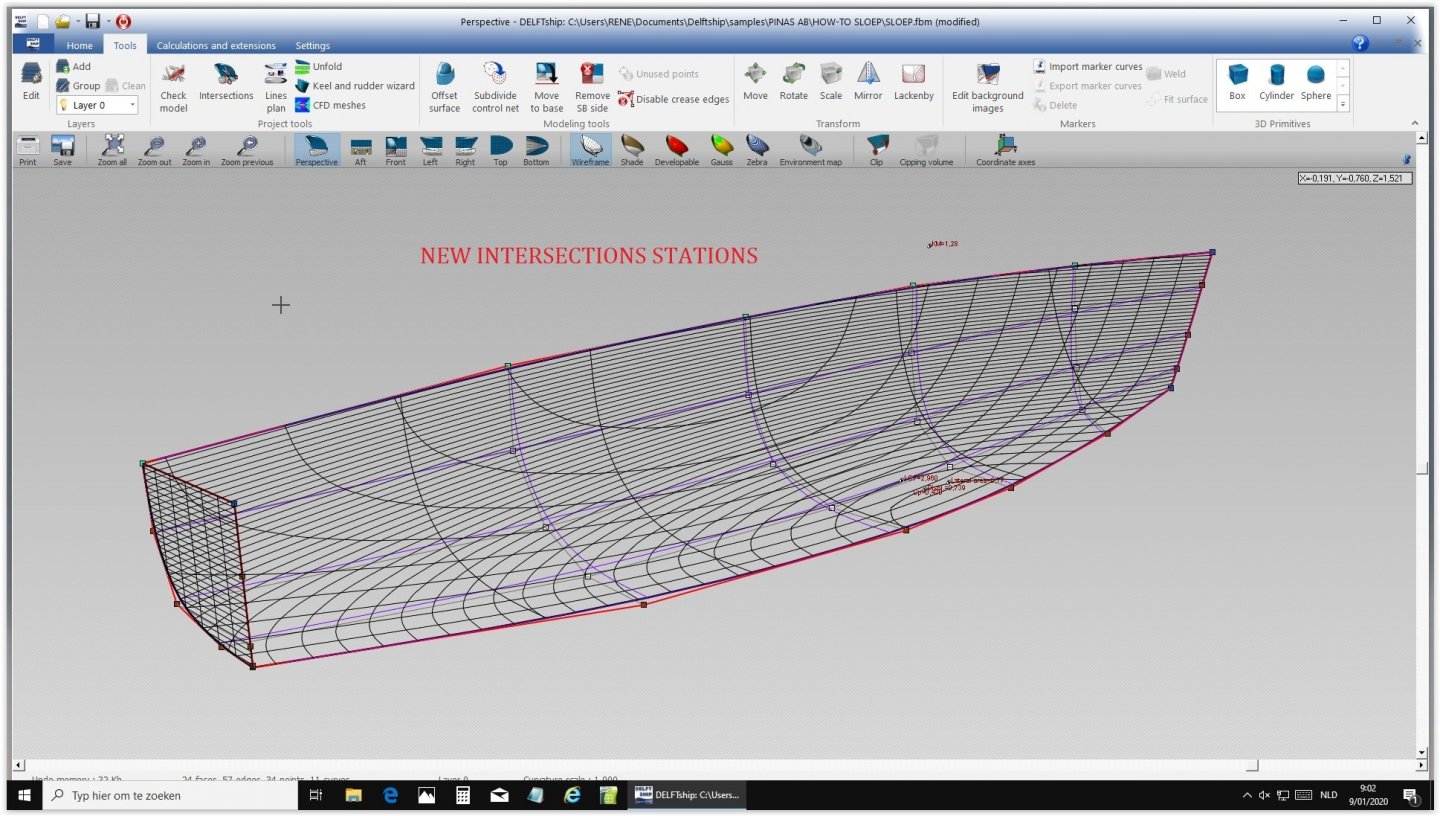
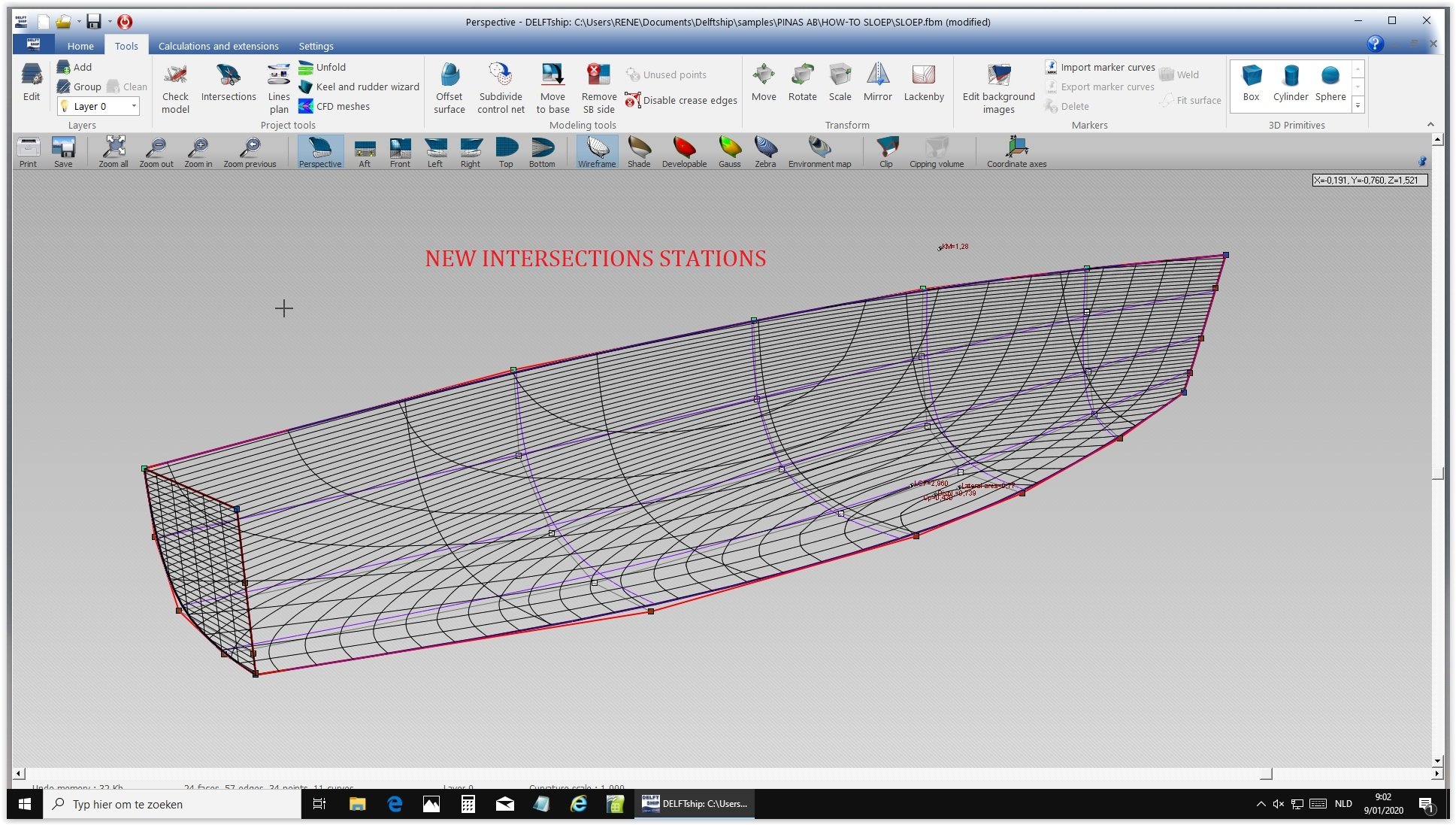
The points of the grid are on the skin only where there is a sharp bend.
- thibaultron, tkay11 and bruce d
-
3
-
Hereby the first suggestions by Rene:
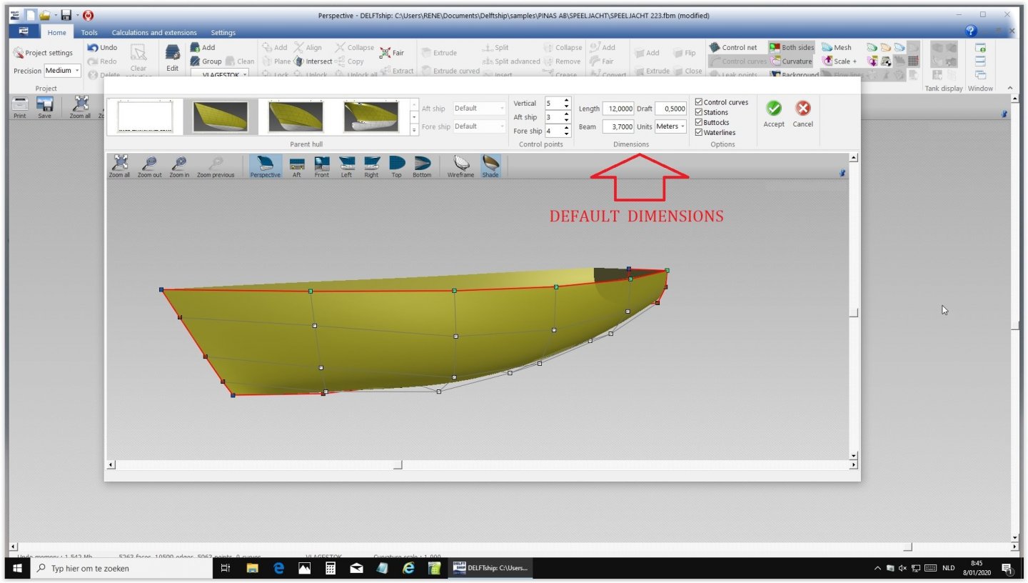
1 By default DELFTShip offers a pattern for a classical type of yacht.
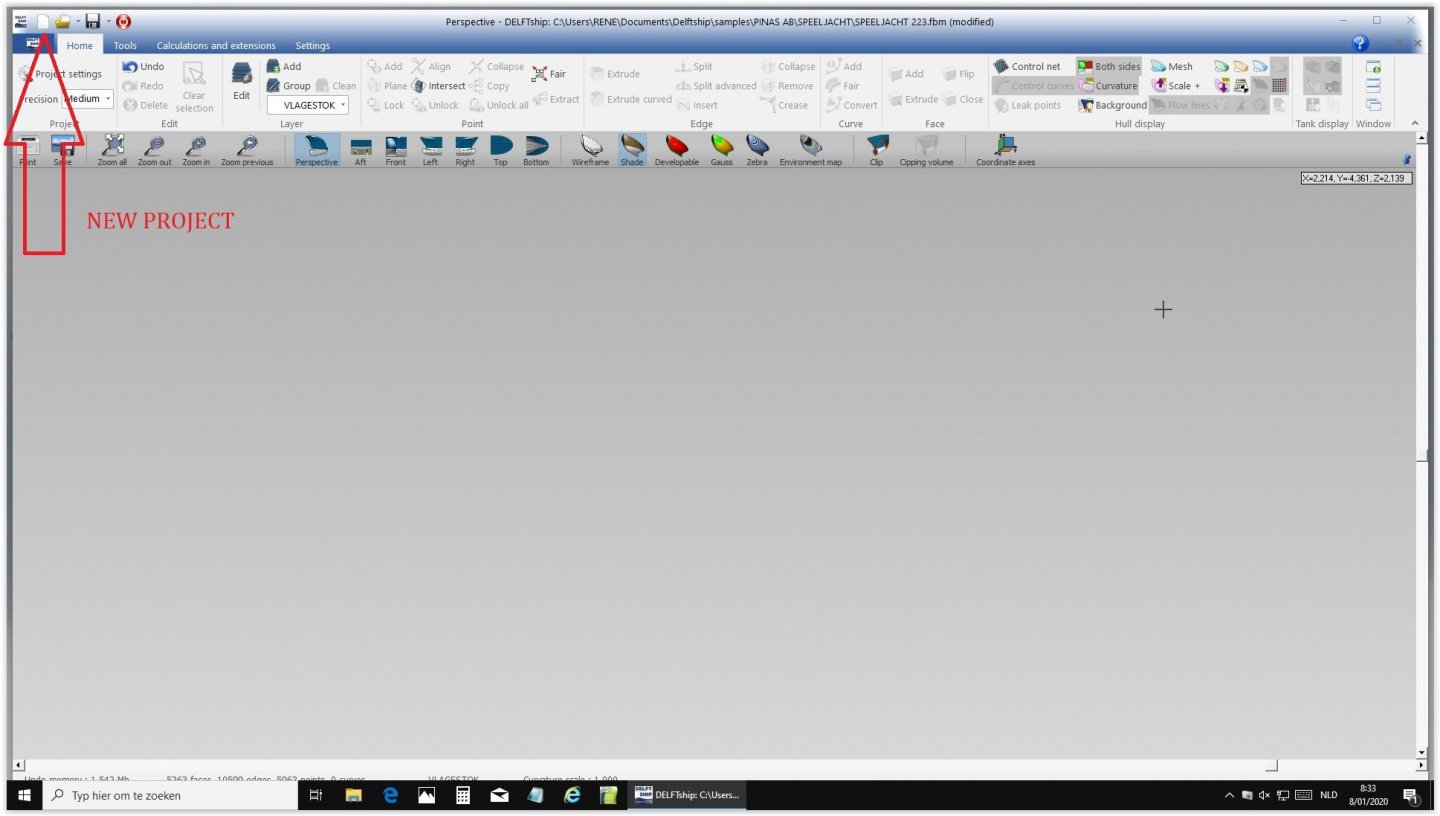
The first challenge is to change that into the shape you want.
Here the modified dimensions:
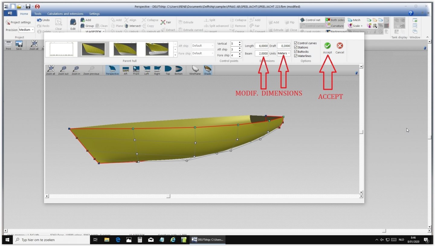
Save as whatever you want.

Here is the file:SLOEP.fbm
Next time more.
- bruce d, Kris Avonts and thibaultron
-
3
-
Excellent Marcus, you are on the right track now!
Next be aware that your real planks should curve upwards to the stern to get the sheer you want.
Always keep an eye on the lines....
- mtaylor, FriedClams and tarbrush
-
3
-
Hi Kris,
Personally I am not a man with enough skills and knowledge to make you any wiser, but I work with my favorite - co-operator Rene Hendrickx. I asked him to make a sort of mini tutorial how to transfer a 2D lines plan into a 3D image with the help of DELFTship. I will post his contribution here as soon a possible. Hope it will bring you some new insights.
Ab
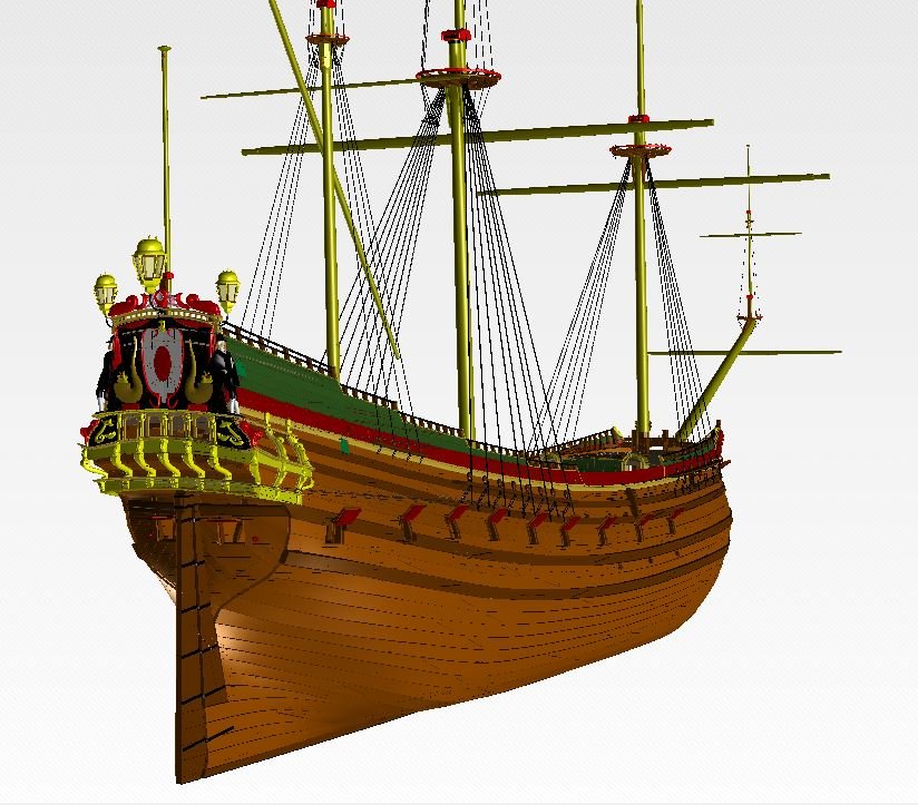
Oh, and eh... the ship I showed is a masterpiece indeed. We worked almost three years on it and it is now in the process of being worked around in a virtual world environment on an internet site, allowing you to walk around in the ship and extracting information from every constructional part of the vessel.
'Soon to be seen in this theatre...':-)
- Kris Avonts, thibaultron, bruce d and 1 other
-
4
-
Ever heard of DELFTSHIP? Free downloadable ship design program. Only a few points at the surface of a hull are enough to get a perfectly designed hull.
-
Call them what you want. You want to complete the missing parts of the top timbers and find their shapes. You can do that by making molds, for instance from card that you fit and adjust to the inside of the flexible battens until you have found the right shape of every missing part.
-
-
Helo Marcus,
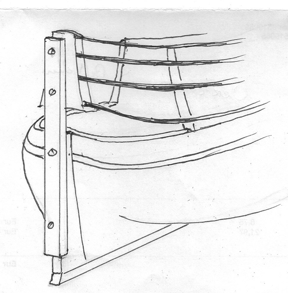
I don't think this method will lead you to the desired result. The lines don't end in a sharp angle.
May I suggest a different approach?
Screw a firm batten to the back of the sternpost and attach a taffrail-shaped temporary mould to its front side. You can pick the shape from the draught. Then work with flexible battens of 4 x 4 mm following the sheer of the hull. Start them at least from the midship area and attach them to the taffrail mould. Make sure they follow a natural curve. If necessary help them a bit by shaping the battens. If all is set in a satisfactory way take the shape of your top timbers from the inside of the battens.
Maybe this clumbsy sketch makes things a bit clearer.
- GrandpaPhil, mtaylor, Baker and 1 other
-
4
-
And a happy new year to you.
Excellent question. How stupid if me.
Website Seahorse: https://seahorse.pl/en/
Good luck
-
I like kits, but I am basically a scratch builder and I especially distrust kits of Dutch old ships. This is caused by the fact that the Dutch never made as much good material available to model builders, like for instance the English did, mostly because the Dutch never made plans of their vessels. This results in kitmakers producing fundamentally wrong models.
Making a card kit of a replica of an old Dutch ship is a smart solution. The research for the Duyfken was mostly done in the end of the 90s by Nick Birmingham in Fremantle, Western Australia, where the replica was built. I had the honor to be invited to visit the project as an advisor. I spent a wonderful week there.
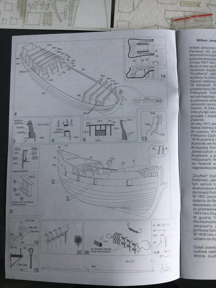
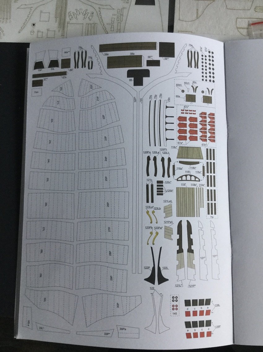
Eight days after my order the package with the kit was delivered from Poland, which is remarkably shorter than some years ago :-). It consisted of a 14 page booklet with 8 pages of parts and 6 of explanations, both in text (Polish and English) and very clear diagrams.
Apart from the basic kit you can also order blocks, gun barrels and lasercut sheets (3).
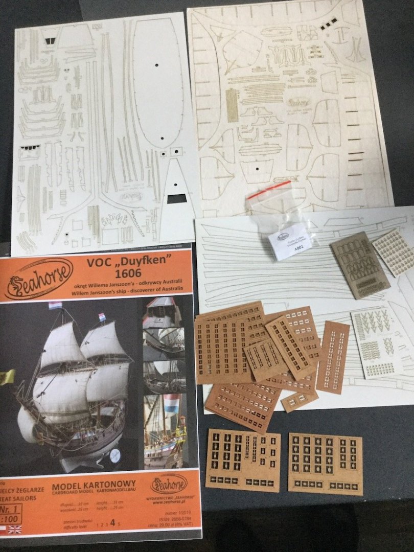
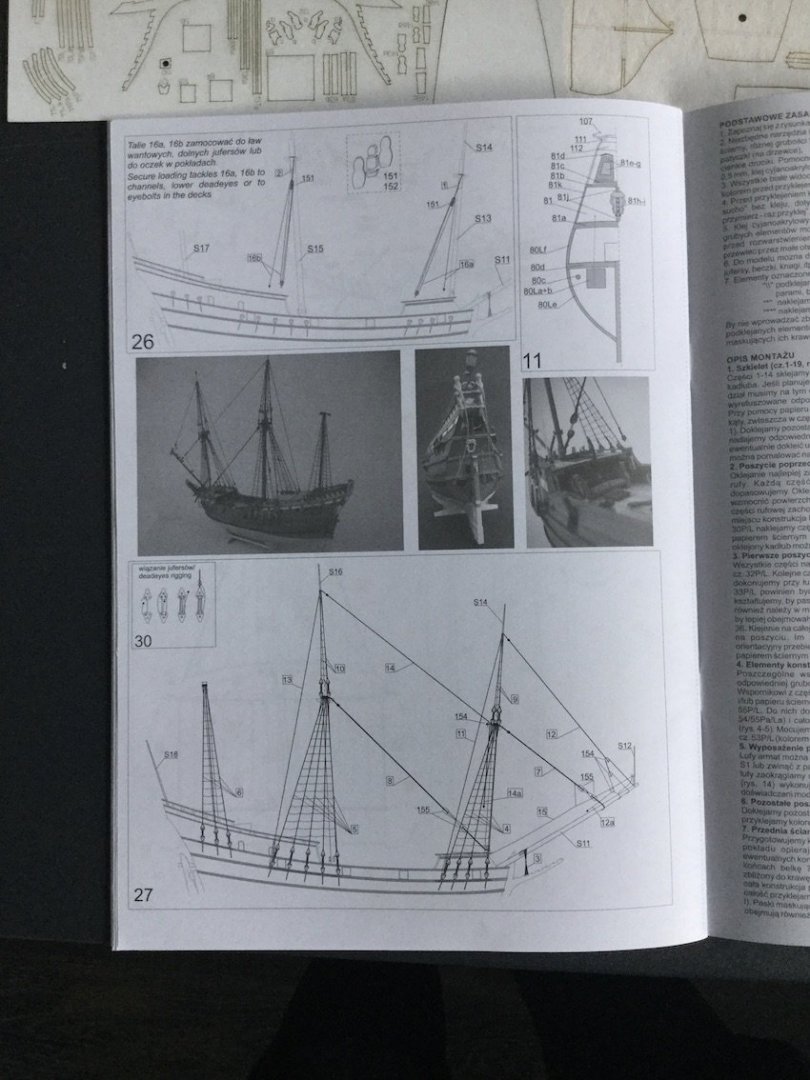
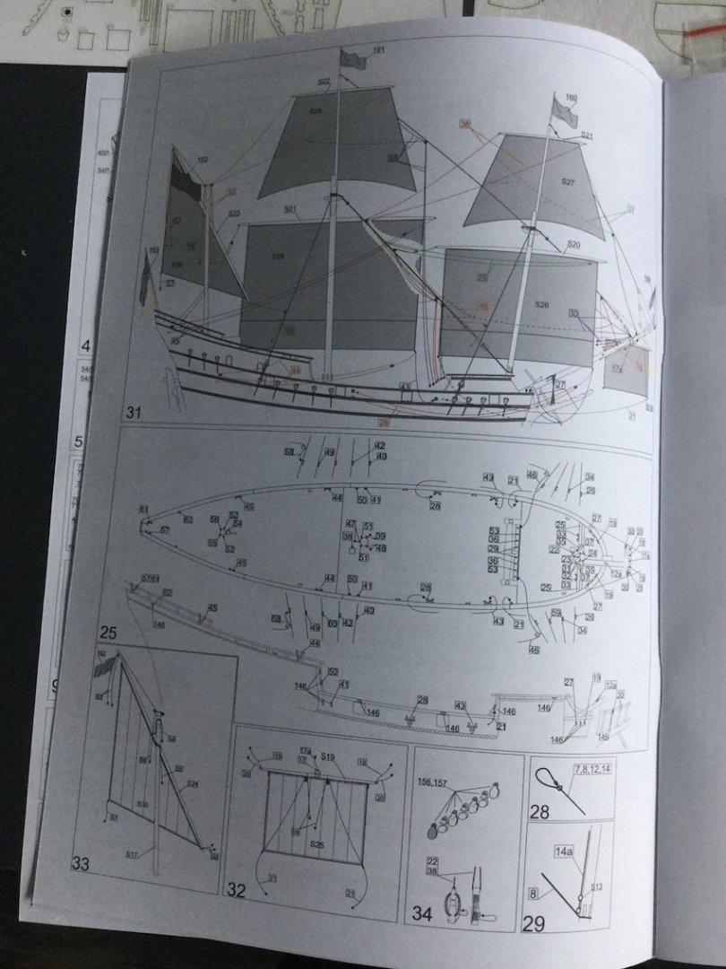
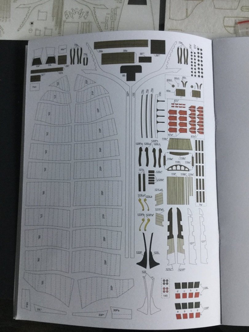
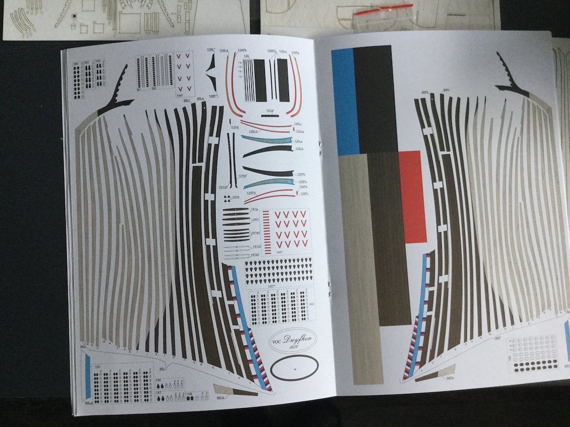
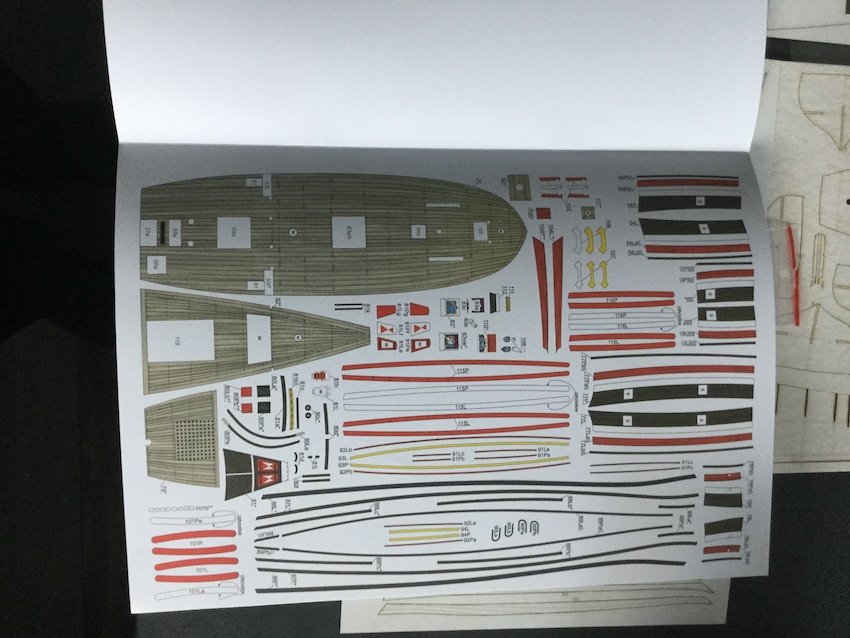 The whole package is very well produced with good printing and fine colors. I was especially interested in the inventive way Tomek Weremko, the driving force behind his new kit company Seahorse, does his planking. (see his threads her under 0Seahorse, like this one amongst others:)
Paper kits usually have problems with producing fair lines, often caused by the ribs showing through the planking. We know from his postings, also at Papermodels.com that Tomek has a method of making beautifully fair hulls without any use of filler. He is demonstrating this technique in this kit, which will be an eye-opener for many of us.
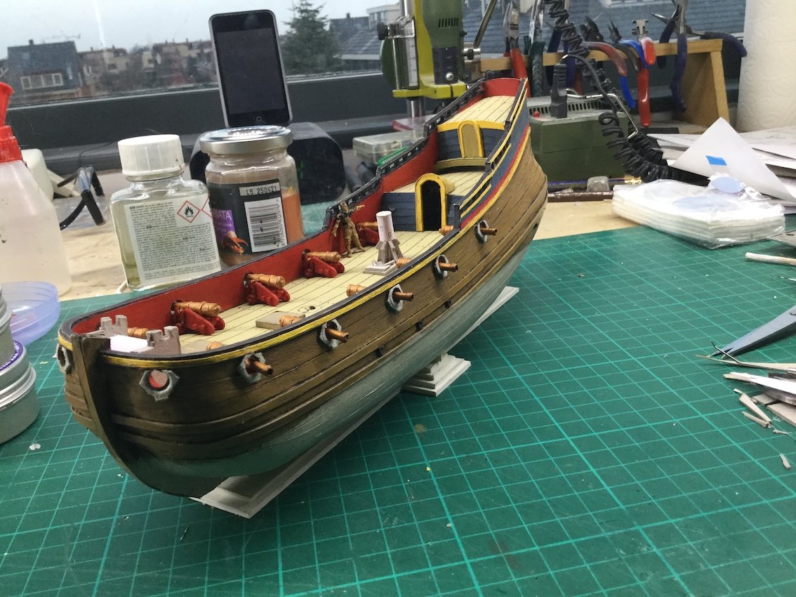
The scale is 1/100, which is very small and the builder ends up with a 31 centimeters long model, although the hull is only 25 centimeter. A real challenge for the miniature lovers to build this humble ship, which was the first vessel ever to map parts of North Western Australia early in the 17th century.I can strongly recommend it!
Ab
-
I glue my glass containers with white spirit for cleaning my brushes to square pieces of old cutting mats. Safe and cheap...
- Captain Slog, Bob Cleek, Canute and 2 others
-
5
-
Not very much.
Of course there are vertical timbers connecting the planks and other timbers to which the planking of the taffrail is nailed. There must also have been small knees to connect side and stern and there were a few decks with their clamps and beams. All together they kept each other in place.
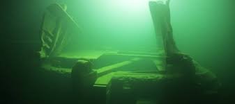
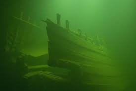
I don't know if you have seen the pictures of the 'Ghost ship' in the Baltics. The one with the upwards staring knight heads. When the ship hit the seabed at 120 meters the mizzen mast fell backwards, destroying the whole after structure....except the sides. They still stand straight.
- GrandpaPhil, mtaylor, Roger Pellett and 2 others
-
5
-
Patrick, do yourself a favor and throw that book into the dustbin. There is nothing in it that has any relationship with real Dutch ships. It was published way back in 1969 by a group of German people who had not the faintest idea what Dutch shipbuilding was all about. In those days it might have been worthwhile, but nowadays the best thing I can say about it is that it is hopelessly obsolete. And I am withholding myself. 🙂
- Baker, Ondras71, FriedClams and 2 others
-
5
-
Try a plane by Halinski, for instance the Hurricane. Good chance that you get hooked.
- mtaylor, Canute and popeye the sailor
-
3
-
Seems to me that you are a real convert when it comes to paper modeling.:-)
- popeye the sailor, mtaylor and Canute
-
3
-
8 hours ago, Roger Pellett said:
Am I correct that the oval piece surrounding the rudder port, yellow in the 3D rendering is actually a structural member tying the upper and lower hull sections together?
Roger
No, I would not call it a structural member in a way that it supports or connects other parts, but it sure has more functions than a decorative one only. It covers the cross-cut ends of the planking, and it adds to a more structural look of the situation there.
We see that in other places too, for instance in the elaborate stern and quarter gallery decoration of the big ships of the era. Here the large horizontal deviders are being supported by many carved figurines, giving much strength to the whole structure.
But without all these decorations the ships are absolutely capable of doing what they were built for.
Does that answer your question?
- FriedClams and mtaylor
-
2
-
That's the spirit Marcus, when the going gets tough, the tough get going.
- FriedClams, Baker and Blue Pilot
-
3
-
Ron, as to your remark about the chainwales of the model at different heights, I think I know what the reason for that is. I was Park Canada's guest in the nineties in Ottawa, when this project was in its early stages. Robert Grenier and Brad Loewen studied this Basque whaling ship, which was found in Red Bay in a very inventive way: all the parts that were found at the seabed were meticulously measured and executed in wood at a 1/10 scale, inclusive all holes for trunnels and nails. The original wood was put back into the water for better preservation. In the lab all the separate parts were put together again, thus trying to unveil the method of building. I am sure that the chainwales that were found, only fitted where they were placed on the model. I agree it is unusual, but I know these researchers did a thorough job.
That still does not explain the nasty rail on top in the back of the ship...
-
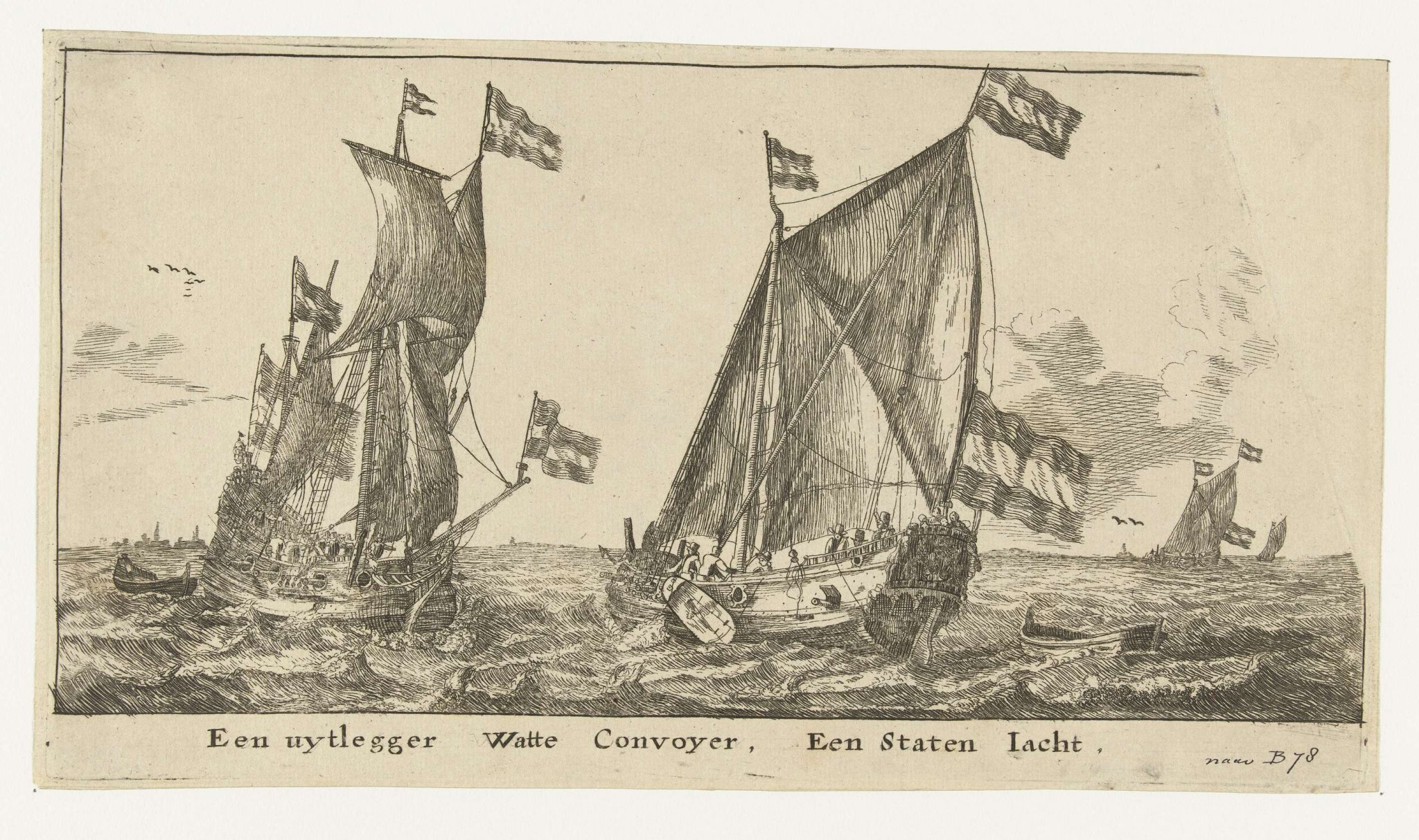
Remember Marcus: many people ran into the same problems with - as you do here. It is a very tricky shape to make. Many gave up. To tell you the truth, I discarded a small fluit-like model myself a month ago. (Edit: I just discovered that I told this story earlier. Sorry for that. It's the age, you know 🙂 ) I was trying my hand at a rather unknown type of ship, a 'wadconvooier', a small armed vessel to convoy merchants on the Zuiderzee between Amsterdam and the inlets between the islands up north the country. All I have as a source are some contemporary pictures, showing different vessels with the same function. On some pictures the type looks like a Statenjacht with an additional mizzen mast, on others it resounds the shape of a fluit. Nevertheless I (also) tried my hand at the fluit-like type and tried to get the widest point of the hull at the hight of the upper wale. I seriously failed because I used a design for another fluit, which was incorrect in this context. The model disappeared into the dustbin and I started anew.
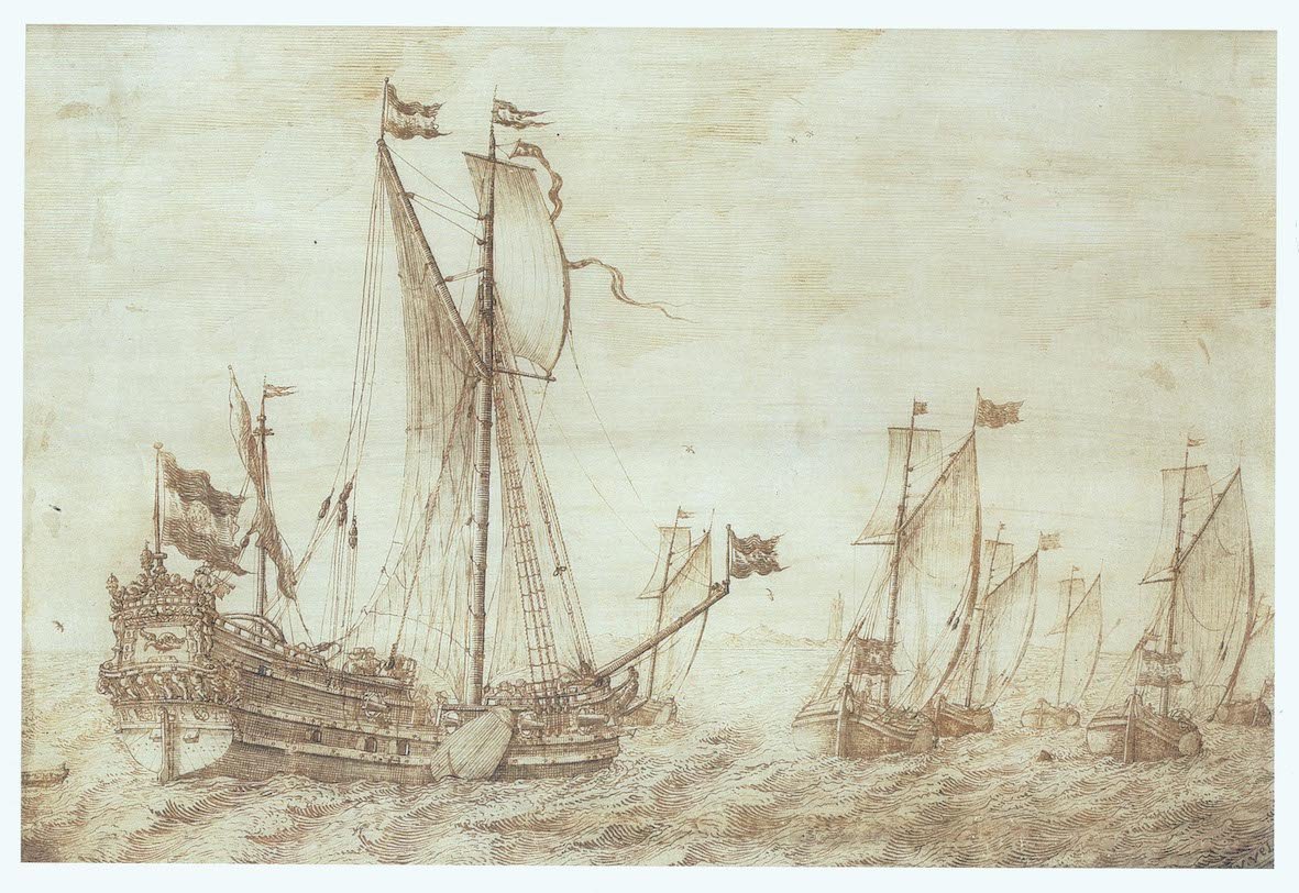
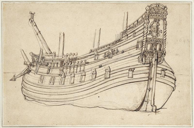
This is the Statenjacht-like type of the wadconvooier.
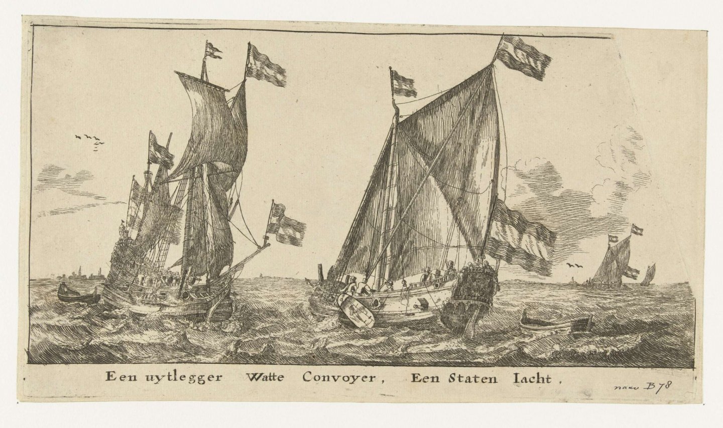
To the left another 'watte convoyer' of unsure type. Probably fluit-like.
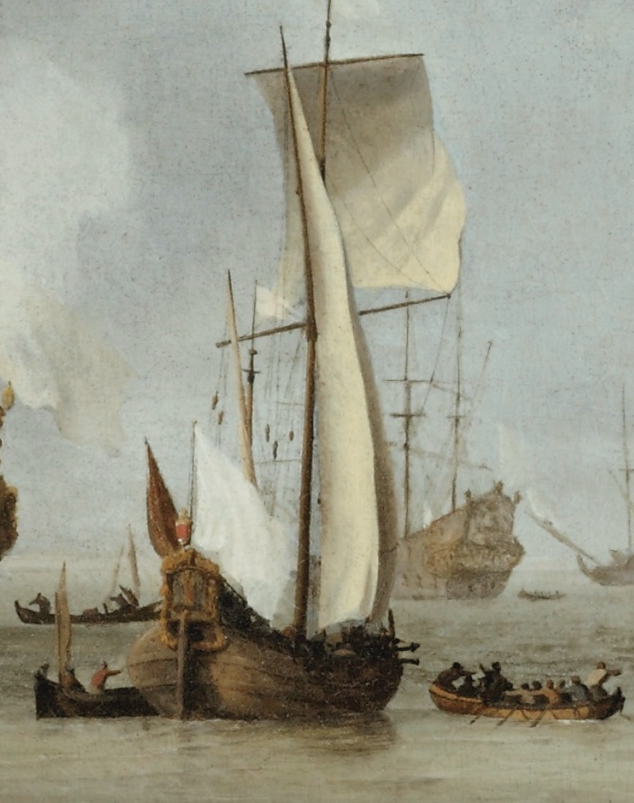
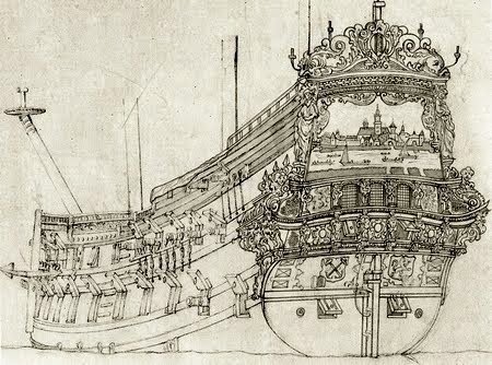
Here an obvious fluit-like type. Mind the widest point at the second wale, where the man in the boat points at, as if he wants to warn me....
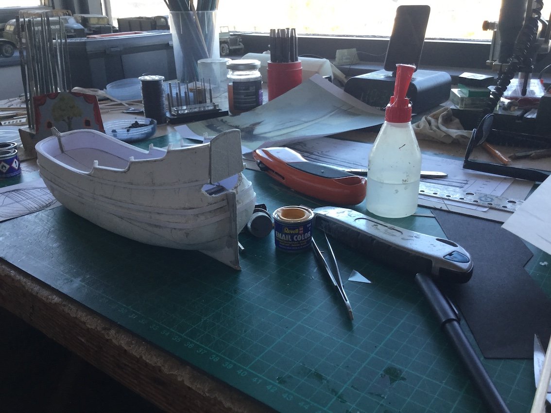
And here my first try, with a shape I did not like. As you can see the widest point is way too low. So it ended in the dustbin.
And here the second try. The shape of the 'hips' comes closer to the one on the painting, but I'm still not completely convinced. This one might end up in the dustbin too...
All I want to say Marcus, is that there is nothing to be ashamed of if you remove parts of your model, or even if you start all over again. Because remember, a mistake made in the beginning of the building process is like a pregnancy: it will only get more and more visible. 🙂
Now you still have the chance to improve your build. Take it.
Ab


Need CAD type program
in CAD and 3D Modelling/Drafting Plans with Software
Posted · Edited by Ab Hoving
Here is how to insert the top view:
Select 'top' in DELFTship.
Then: 'edit background images'.
Choose your top view and import it into DELFTship
Click and hold top view and drag it until stern and centerline are equal to the DELFTship stern and centerline.
Stretch it till they fit.
Click and drag the DELFTship lines until they match with the new design, just like you did in the side view.
Next time the body plan, but I think the system becomes clear now...