


Kevin-the-lubber
-
Posts
1,215 -
Joined
-
Last visited
Content Type
Profiles
Forums
Gallery
Events
Everything posted by Kevin-the-lubber
-
 To be honest I'm not sure I can, which makes my day. You've made a very good job of the painting, that's for sure. If I had to guess I'd say the two pairs in the middle are mine? Have you tried the blocks yet? In both instances, please critique freely, it'll only lead to improvement.
 -
While messing around a couple of weeks ago aimed at making whisker booms from copper wire, I just used my plumbing blowtorch and plumbers lead-free solder, as I always have some of that in the toolkit. I prefer using a flame rather than soldering iron, just because it's quicker and you can draw the solder to where you want it a little more easily. As and when I see myself doing this for real on models, I'll look for a true mini-torch, for ease. There's are loads of 'mini's' on amazon but they mostly look like standard size. I wouldn't spend too much either. A torch is a torch.
-
Soldering is great for stuff like this, it’s bombproof. It can take a little practice to get it to flow only where you want though.
-
3d printing process
Kevin-the-lubber replied to henrythestaffy's topic in 3D-Printing and Laser-Cutting.
Dr PR, thanks, that's given me some ideas. I hadn't even thought about the squeezing aspect. But most of all you're confirming that there's nothing wrong with the machine, this is user error, which is good, because I can fix me but not the machine 🙂. I think my problems fall into the category of '99% of the time you'll get exactly what you sent to the printer. 1% of the time you're going to have to work at it'. I read an article a while back about ideal angles and I don't think it was 45 degrees. It was all about the arrangement of the pixels. Generally, I just try to reduce the amount of surface tension, balanced against the wasted cost of supports. -
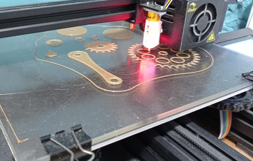
That looks more like it. The resolution capability of these printers is, as you say, outstanding. I haven't tried the phrozen resin. I find elegoo abs very good, but unrestrained objects can warp a little over a few days post-curing; and I've been using syratech fast for when I want more strength or rigidity, but at a slight loss of detail. I'm going to splash out on one bottle of syratech blue shortly, just to see whether it really is the bees knees, as I have some very, very small load bearing things that I'd hate to have to replace if they break along the way. I'd reiterate that it's worth paying close attention to the detailed settings, usually available on the manufacturers website, and not just altering the exposure time. Slowing down the lift speed has been a game changer for me on a few objects. On a completely different topic, Richard, I'm going to try my first hull shortly - only a tiddler, a simple little jolly boat, but I'll be going back through your video for all the tips and tricks.
- 454 replies
-
- 2
-

-
- Union Steamship Company
- Stepcraft 840
- (and 3 more)
-
It seems unlikely there'd be two GF Campbell's, both writing about clippers, but who knows! I picked up somewhere in my recent reading that he was a naval architect.
- 481 replies
-
- 1
-
-
- Cutty Sark
- Revell
- (and 2 more)
-
Ps. I’ve also found that adding some meat to frames where that is hidden can make a lot of difference i.e. do a flange around the back and recess it into the bulwark if necessary.
- 454 replies
-
- 2
-
-
- Union Steamship Company
- Stepcraft 840
- (and 3 more)
-
Richard, I’m guessing that your walls are about 0.3 to 0.5? It looks too like you’re printing straight off the plate. I’ve found with small, delicate pieces like these that it’s best to angle them and use thin supports. However, anything this thin will be inherently fragile unless you’re going to put strength back with the glazing. It’s also worth trying different resins and religiously using their recommended settings as the base, paying attention to things like lift speed. I’ve just started learning that these can make the difference between ‘perfect’ and ‘fail’.
- 454 replies
-
- 2
-
-
- Union Steamship Company
- Stepcraft 840
- (and 3 more)
-
Bill, did you solder them? I know this sounds mad but years ago, when I still smoked (silly man) I was given a lighter than is like a mini-blowtorch, which is just right for this kind of thing!
-
3d printing process
Kevin-the-lubber replied to henrythestaffy's topic in 3D-Printing and Laser-Cutting.
Thanks Ron, Paul. I should have found some other examples but this was all I had to hand; this outcome happens to some degree or other on all kinds of larger pieces regardless whether it’s tilted and even with a dense array of heavy supports. A little while ago I was printing what in effect is a simple box with no lid or bottom, about 8cm x 5cm, with a 2mm wall thickness. Whether angled or flat, it would warp during the print. Yet I can load up the plate with loads of individual smaller objects and have no problems. Equally, I’ve printed some large-ish delicate things using only thin supports and been fine. It’s perplexing. For the object in the photo I did indeed print it edge on in the end, this is fine when that’s an option but sometimes the orientation options are limited. -
3d printing process
Kevin-the-lubber replied to henrythestaffy's topic in 3D-Printing and Laser-Cutting.
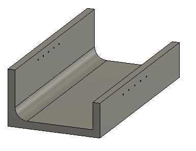
Hi Ron, you mentioned you've found some good forums for resin printing - would you mind sharing the links please. I've found it quite difficult to find anything outside of facebook, which I simply won't use, and have a recurrent problem that I'm struggling to fathom. I doubt it's unique and some of the old hands will most likely point me in the right direction. In case you're interested, it's this; This is supposed to look like this; As you can see, the bottom gets ripped off the (heavy duty) supports and warps into a curve. This is not a particularly large piece and, although in this instance I've printed flat, the same kind of thing happens on anything large where I need a straight edge. It can't be a question of just adding more support, if there was any more it'd be ridiculous. Something similar happens if I print it straight onto the plate, you can see striation where the layers are being pulled apart. I think it may be something like the FEP isn't sufficiently tensioned, or that the settings need adjusting, but I'm always a bit fearful of playing with these too much in case I tear the FEP etc. On the larger printers this gets expensive! nb - I do wish that test was available for elegoo printers, but unfortunately it's not. There are plenty of generic test pieces out there but none that, like this, change the printer settings during the print so you can just do one test.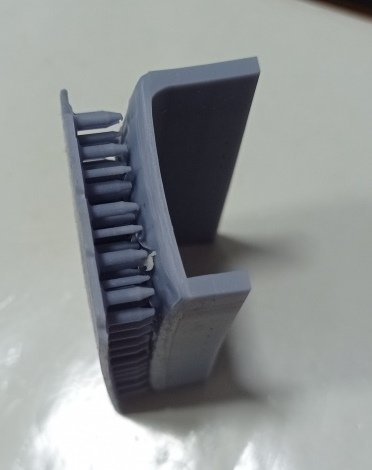
-
Bruma, can I take you way back to post #5, where you drilled the deadeye holes in line with Campbell's plan. Did you look at whether these new positions might cause any fouling, especially those for the mizzen? I'm asking because this evening I'm fine tuning my replacement bulwark rails and there is a significant difference between the spacings and positions of the deadeyes between revell and campbell. I'd much rather use campbell as this gives more space for the belay pins but I'm nervous that by moving the deadeyes aft, the mizzen backstays might foul the quarterdeck pinrails or cabin rail. I imagine this is unlikely but thought it worth asking.
- 399 replies
-
- 2
-
-
- cutty sark
- revell
- (and 2 more)
-
Which book are these in, or site? Although I do find the campbell plans a tad sketchy (literally), in his defence he seems to have published a fair bit on clippers, leastways I have his book 'China Tea Clippers' which goes much wider than the Cutty Sark.
- 481 replies
-
- 1
-
-
- Cutty Sark
- Revell
- (and 2 more)
-
And I'll happily be Mr man-in-the-middle. Clearly the boss (he gets to sit down), and you wouldn't want to meet him in a dark alley :-). Though in reality I'm probably more that chap lurking in the background. It's a fantastic photo though, isnt it.
- 481 replies
-
- 2
-
-
- Cutty Sark
- Revell
- (and 2 more)
-
I read, in either Hackney or Campbell, that there were iron plates on the deck for the chain. Likewise, that the fore hatch was much smaller. I also read that when first built, there was only one deck cabin, the second was added a couple of years later, though Hackney didn’t mention which one.
- 481 replies
-
- 1
-
-
- Cutty Sark
- Revell
- (and 2 more)
-
Shipman - now there’s a thought. But one I’d only turn to as a last resort. As a variant on that theme, it’s quite easy to model and print rope I.e. to remake the revell parts but better, but I know I’ll get far more satisfaction from doing it for real. Rob, wise words. I don’t want to get bogged down and, a bit like bcochran, wil be happy enough if the end result looks reasonably “shippy” and not too much like some plastic moulded toy. bcochran, you and me both. But I have a feeling that between the three of us, including Bruma, we’re going to learn a lot more about rigging by the time we finish. I also really struggle with the very fine detail and small parts. These hands were made for building full size ships, not miniatures. I think the revell blocks have ring bolts don’t they, and I’ll probably do the same, just pretty them up by serving the ropes. Ian, I think that’s the nail being hit on the head. At this point my reference is the kit parts. Once I’ve done the reading on them, I start to see what’s missing and whether I want to remake that part. This has been fairly easy so far as the ‘body’ is relatively simple, but nevertheless I’m figuring out some stuff, like the deck height, too late in the day.
- 444 replies
-
- 2
-
-
- Cutty Sark
- Revell
- (and 2 more)
-
Rob, I meant wool. Not that I’m at all pinning her to any particular era, just wanted something in the hold. At one point I thought of tractors, but when I started googling I got in trouble with my other half. (Sorry, highly contemporary Brit joke). I tried tea chests but unless you scatter them they just look like a square block, whereas the wool bales at least have a bit of shape. Thanks for explaining spreaders, the cross trees etc on this model are still a mystery to me, but I guess it’ll all fall into place once I start looking at it properly. Ditto going out of scale on the deadeyes. 2mm really is a bit too small, I think I’ll bump these up to 3mm and the 3mm to 4mm and see how it looks. I think there’s a link here with the discussion over on your Glory build about perspective distortion, that the viewer has a certain expectation. In my case, when I look at properly scaled deadeyes they simply look too small, they lack the presence of those on the real ship.
- 444 replies
-
- 2
-
-
- Cutty Sark
- Revell
- (and 2 more)
-
Hi Ian. You've given me some homework (which is fine) - spreaders... I think I'll probably need to assemble the masts in order to understand the rigging points, so that I can then understand if and where the kit parts are wrong; and accept that if I make a complete pigs ear of the masts I'll have to remake them (but not printed, that's not good for these).
- 444 replies
-
- 2
-
-
- Cutty Sark
- Revell
- (and 2 more)
-
This is the deck being too high. The hull itself seems fairly true to scale but this one strange decision imparts on many things, from the hencoops to the windlass. If I was starting over (and there are still moments where I eye up the spare kit) I'd almost certainly lower the deck, but I guess one could also reduce the height of the cabins. But I think anything other than lowering the deck and you'd be chasing your tail. Well done getting the pinrails in, and the fore and stern rails. I have quite bad warping on these kit parts which is what tipped the decision to remake them.
- 481 replies
-
- 1
-
-
- Cutty Sark
- Revell
- (and 2 more)
-
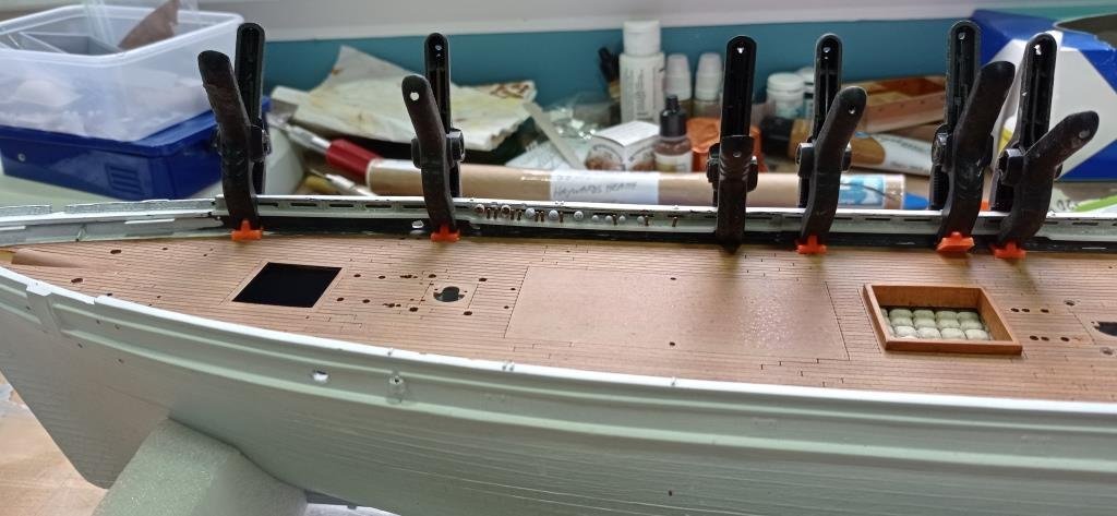
I read, probably in Campbell, that the first deadeye should be dead in line with the relevant mast. Is this critical? Now's the time for me to tweak it. I took the positions off campbells drawings and currently they look just slightly aft of the masts. Logic also tells me that the deadeyes would be equally spaced across their group, is that correct? Just how critical are the positions of the deadeyes in the grand scheme of things. I sense the answer is 'not very, within reason'. I'm at the stage of printing the replacement rails for real, so at this point I'd want to finesse the positions of the deadeyes and belay pins. As you can see, I'm incorporating the 'lozenges' by having very thin sliver of a 'cover' that glues to the inner bulwarks. The ribs in between the lozenges hopefully give a bit of added strength but in any case, having the deadeye stanchions glued down at the waterway should mean there's no real strain on the pinrails. bcochran, we're on the same journey and I'll be watching your log as much as my own. I started reading the Hackney book last night, not a bad place to start because, until the simple terms start to mean something I final the likes of longridge far too heavy going. Rob, these lower deadeyes are going to be very challenging to reeve, especially the little 2mm one's. Probably a little easier if the thread slips easily through the eyes, on my practice piece I needed to use a sewing needle threader, but I don't think that'll be possible with them in situ. (Note the cotton bales in the main hold. I wish I hadn't glued them in now, seemed like a good idea at the time as I felt my lack of progress was all about just glueing some stuff in place, but I subsequently changed my mind about what I wanted it to look like. Too late now, it'd take more than acetone to get them out, so I'll just live with it.
- 444 replies
-
- 4
-
-
- Cutty Sark
- Revell
- (and 2 more)
-
Thanks Rob, that's helpful. It means doing the masts and tops first, as the shrouds determine the heights of the upper deadeyes, but I can see that this is a good method. Scratches head... so where do I go from here... start making a serving machine of course.
- 444 replies
-
- 2
-
-
- Cutty Sark
- Revell
- (and 2 more)
-
That's the thing with such a great forum - it's all in here, you just have to find it. The search function is pretty good though, I've used that to good effect a few times.
- 444 replies
-
- 1
-
-
- Cutty Sark
- Revell
- (and 2 more)
-
That is pure quality. I would think twice about painting these, they are stunning as they stand. And you made all these by hand?
- 399 replies
-
- 2
-
-
- cutty sark
- revell
- (and 2 more)
-
That's a good suggestion, thanks. I'm kind of hoping that someone, after they've stopped rolling around at the floor with laughter, is going to show me a simple way that everyone else uses.
- 444 replies
-
- 1
-
-
- Cutty Sark
- Revell
- (and 2 more)