


Kevin-the-lubber
-
Posts
1,232 -
Joined
-
Last visited
Content Type
Profiles
Forums
Gallery
Events
Everything posted by Kevin-the-lubber
-
 It would, but I’ll most likely print in three parts: the body, and the two wheels + handles. This would be tricky on FDM, I’d probably have to use use brass wire for the crankshaft and conrods but even so, doubt I’d get a quality of finish to make it worthwhile. I might even have to do that for this one as the shaft and rods really ought to be about 0.5mm at most to be in scale, but I’ll see how it looks when printed. I enjoy the painting more than anything, when it goes well. Still struggle to map the colours in my mind with those in the pots, but that will hopefully come with experience.
- 444 replies
-
- 2
-

-
- Cutty Sark
- Revell
- (and 2 more)
-
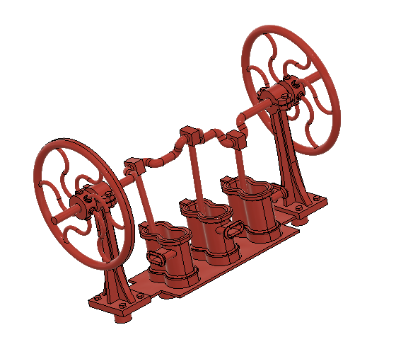
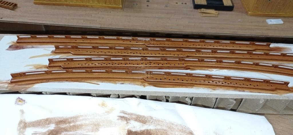
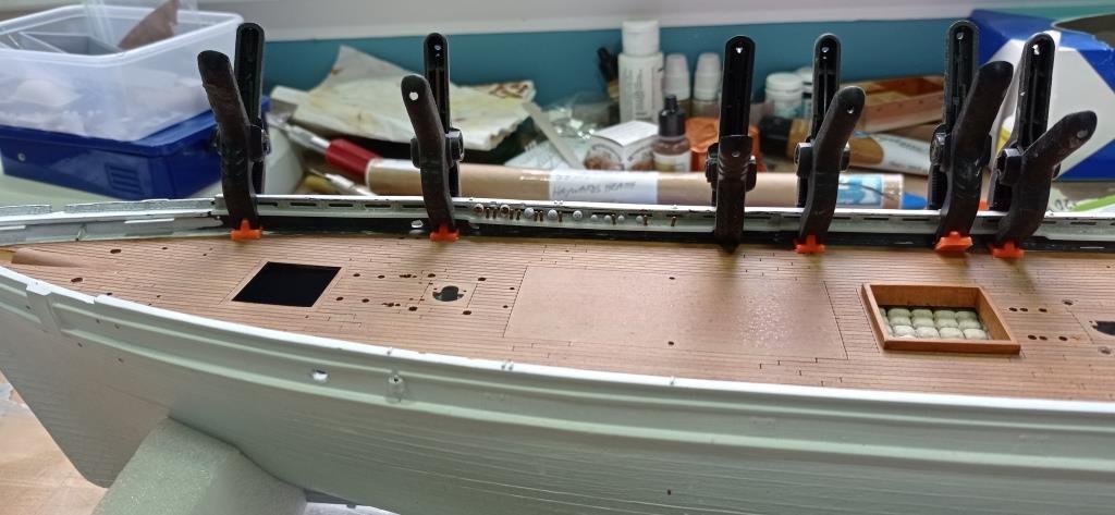
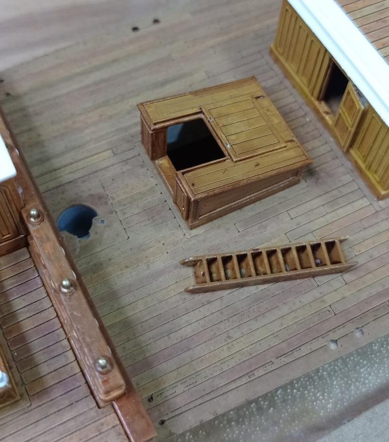
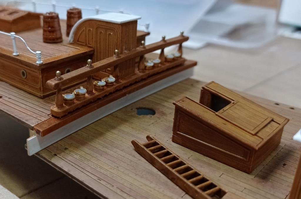
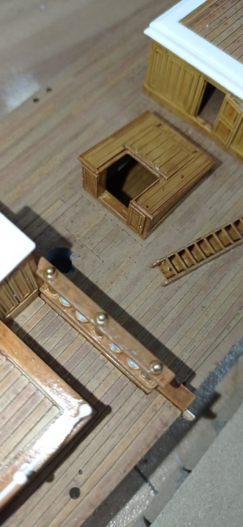
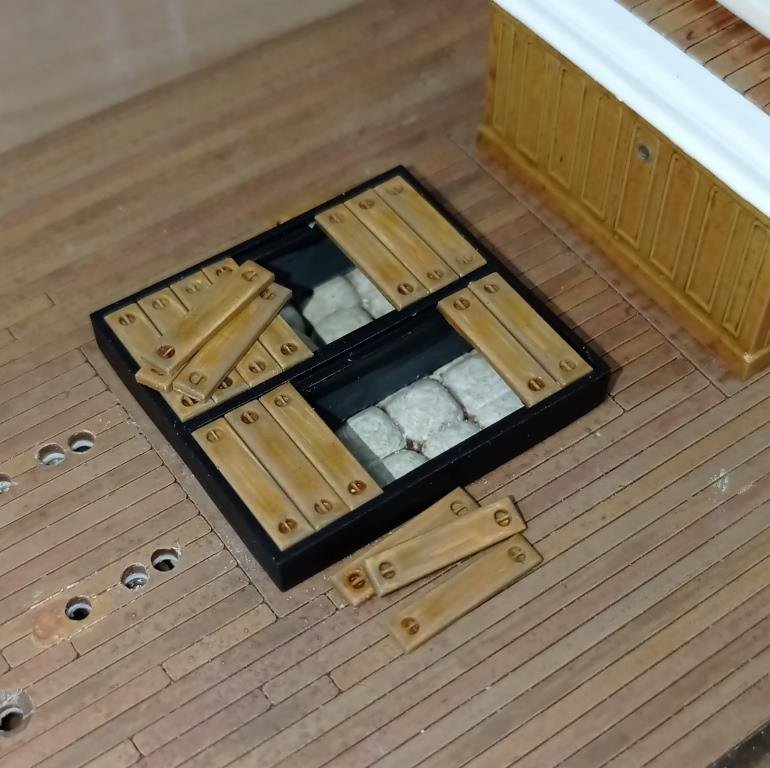
I ran out of paint for the hull at the weekend - I can't think why I thought one small bottle of vallejo metallic would be enough - so while waiting for more to come I've been finishing off a host of bits and bobs. This is the main hatch, borrowing the partially covered idea from Rob's Ferreira. I want a bit more contrast, colour-wise, on the deck but I'm not sure I'll keep the planks this colour, might try something darker. Still need to make the lifting hooks as these would have been pretty heavy. Not entirely decided about the front hatch - planked like this at the moment but I might try making a tarp at some point. Booby hatch, with a ladder once glued in place. I've gone about as far as I'm willing research-wise on the hatch and in the end made some guesses. Buckets. I tried doing real ropes but got fed up after about 30 seconds of trying to tie a knot in the right place on 0.2mm rope. What hope is there for me when it comes to rigging! It doesnt really show up but I tried to replicate the carving on the underside of the lower rail. I painted the tops of the posts using a gold acrylic paint pen - I first crush the tip to get it more 'brushy', then sand it back to a more pointy shape. I love these pens, they deliver just the right amount of paint and the 'goldiness' is really, well, 'goldy'. Trial fit of the new pinrails Pinrails painted and inked, awaiting a painted hull. Must remember to varnish them first. I've had to write myself an assembly sequence/checklist which I'm following religiously, as I realised I have to glue the deck and quarterdeck assembly in before these, else they won't go. This is where I regret a day of frustration a couple of weeks ago that saw me glue one of the cabins in place, just to feel like I was getting somewhere, even though my inner voice was saying "don't". It'll be a pain working around that. I've shifted the holes for the deadeyes & belay pins inwards to try and give myself just a little more room for doing the lanyards. This evenings work. If I coloured it black all you'd see is a blob, so it's racing red for now. I noticed on photo's that the inners of the tubs are painted red, but I expect that's just for show. Just need to make the handles and we'll see how it prints. Unlike the winches, this will be rigid i.e. non-working. It was tempting, but you have to curb the enthusiasm at some point and I'll be happy enough if it prints okay. I made pumps that work like this back in the day, in Kenya. Great fun.
- 444 replies
-
- 5
-
-
- Cutty Sark
- Revell
- (and 2 more)
-
If and when the mood grabs you, I’d really recommend this DIYODE article https://www.google.co.uk/url?sa=t&rct=j&q=&esrc=s&source=web&cd=&ved=2ahUKEwjQuu2YmYf4AhXNYMAKHb6eB_QQFnoECA0QAQ&url=https%3A%2F%2Fdiyodemag.com%2Feducation%2Fexploring_3d_part_1_beginners_guide_to_fusion_360&usg=AOvVaw1q5hCjynXrbTUKYaEWwVl7 Whichever way you go at it (CAD), nothing will be as intuitive as Tinkercad, but this tutorial was pretty quick, easy to understand, and saved me from throwing the mother of all computer generated tantrums.
- 536 replies
-
- 1
-
-
- Quadrireme
- radio
- (and 1 more)
-
Ian, I don’t know how far you’ve gone with F360 but it’s tailor-made for this kind of thing. I animated the moving parts on that little serving machine I made the other week, just to check that I hadn’t made any stupid design errors. But it’s also a lot easier than Tinkercad for creating and editing the parts you have there. I cut my 3D teeth on Tinkercad and still think it’s quite under-rated but, to be honest, can’t see myself ever using it again.
- 536 replies
-
- 2
-
-
- Quadrireme
- radio
- (and 1 more)
-
3d printing process
Kevin-the-lubber replied to henrythestaffy's topic in 3D-Printing and Laser-Cutting.
That's pretty good moulding if that's the kit part! If these ship kits were that decent I probably wouldn't have even got into printing 🤔. I see the difference now, comparing the solidworks snip to the kit part - you're including far more detail. I find that anything extremely small, 1/100 bolt heads for instance, can end up looking like these are 'zits' rather than intentional unless there's a strong pattern, but it's still surprising what you can get away with. I printed the most delicate filigree pieces for the Victory that are only about 0.2mm wide and thick, an absolute nightmare to get off the supports, but I was still impressed that the machine could do this. I guess though that we will always want one more level of detail, it's the nature of the game. -
3d printing process
Kevin-the-lubber replied to henrythestaffy's topic in 3D-Printing and Laser-Cutting.
Phil, the hot water trick was used by Daniel (Dafi) over on his Victory log. I guess if you have a former to shape the object to, it’s probably quite easy to re-shape after softening with a little heat. Whether it’ll hold the shape I don’t know. I agree about cross supports, but I’m sure you have some control options for these in Chitubox? I’d guess that in the paid version you can place them by hand, but I can live without that. Interesting to hear about the customer support, it had never occurred to me to ask them when I have problems like my square edge pet peeve. Egilman, what’s the cream-coloured resin in #259? The result looks better than the grey resin? I use way more supports than you, I’ve just gravitated towards more over less over time, as I was getting frustrated by the fails. To get over my recent hump of fails I had to increase the exposure times quite a lot, the point being that I’m having to use different settings for the same object, printer, resin etc from those which were successful last year. I guess (printing seems to always involve a lot of guesswork!) this is down to temperature, humidity etc. I also built a heated booth for the printers as even in summer the temp in my garage can be quite cool. Basically I just bought a flat pack kitchen cabinet + doors and added a small tubular greenhouse heater. -
3d printing process
Kevin-the-lubber replied to henrythestaffy's topic in 3D-Printing and Laser-Cutting.
Ps. Nothing wrong with free lychee apart from the ads. The only thing I don’t like about it is that you can’t bevel the raft, whereas you can in free chitubox. I only use lychee now when I want to mirror supports functions, which saves a lot of time, otherwise I just find Chitubox easier and much more tolerant on non-manifold objects. -
3d printing process
Kevin-the-lubber replied to henrythestaffy's topic in 3D-Printing and Laser-Cutting.
Manual every time for me. It can be a bit of a drag, doing them by hand, but for our kind of stuff - tends to be small and precise - you’ll more often get the result you want at the first try. One tip: if the item is very delicate, raise it off the bed by 10 or 12 mill rather than the ‘normal’ 5 or 6. Let me go back one step and explain: I remove supports by snipping them off at the raft end first, them gently twist them off the object. The reason for increasing object to bed distance is so that the supports are longer and there is more opportunity for the support to bend when being snipped, as opposed to the object. If they object is super thin and the supports are very short, there is a tendency for the object itself to get broken by the snipping. There are probably other ways of solving that problem, and I’m all ears if so. I hardly ever turn to YouTube as so much of the time the videos are painful to watch, dragging things out forever when 5 seconds would do. -
I’m not sure I ever calculated it out, but for the Victory I could see it was going to cost several hundred pounds in aftermarket stuff and even then I was going to have to scratch build quite a lot, so in theory it made sound financial sense. In reality I have of course thrown around a hundred pounds worth of resin in the bin while learning but, just like FDM, the mistakes and fails are generally less and less frequent.
- 460 replies
-
- 5
-
-
- Finished
- Flower-class
- (and 1 more)
-
It was the cost of buying all the little bits like eyebolts, blocks, stanchions etc that tipped my decision to also buy a resin printer. That and an acceptance that even with a 0.2 nozzle (0.1 was just too painful) and 0.1 layer height, I was never going to get the finish I needed. If you’re at all tempted, bear in mind that there are loads of very good first or second generation resin printers on eBay now, as people upgrade to the newest models.
- 460 replies
-
- 3
-
-
- Finished
- Flower-class
- (and 1 more)
-
While I dare say some may have a view on your choice of colours I don’t think anyone is going to deny that the effect is spectacular, the execution first class and that there’s solid reasoning behind the choices.
- 2,699 replies
-
- 6
-
-

-
- heller
- soleil royal
- (and 9 more)
-
Very tempting, as that too is around the £60 mark. Like you I'm very taken by the raised walkways but also that there's a lot of stuff on the decks. As you know, I do like a bit of detail! It was the raised walkway that caught my eye on Rob's Glory of the Seas. We shall have to see. Not least, how I get on with rigging the Cutty - despite the absence of deadeyes etc you seem to have an awful lot of lines on that ship. I'm reasonably okay with persevering with a difficult problem, less so with endless repetition.
-
Here's the irony - more years ago than I care to remember I worked for a few months in the shipyard in Lubeck, and in Hamburg, though not Blohm & Voss, I'd probably enjoy both experiences even more if I had that time again. But nevertheless, obviously quite different to the Preussen. Seems like plans are not hard to find https://hec.lrfoundation.org.uk/archive-library/ships/preussen-1902
-
9” longer than the Victory is getting large - I guess that’s why they went for 1/150, so it’d still fit in the average house. I read somewhere recently that this was part of the general design brief for these larger models. Its a pricey kit though, about £150 it seems, whereas the Passat is only £65. So many models…. I’d best finish the CS before getting distracted!
-
I don’t know how I’ve missed this log, Ian. I knew you were doing the galley but not this lovely little (not) gem. I must read through the log more slowly presently. This is very much my kind of ship, with all that busy-ness on the decks. Actually, I’ve remembered why it wouldn’t have registered - I don’t think I could handle 1/150. How do you find it compared to the Vic? It looks quite large despite the scale. Either way, it’s looking fabulous. Are there build plans available? Incidentally, if you liked that Eric Newby book (which I haven’t read) can I recommend two others by him - A Short Walk in the Hindu Kush, and Love and War in the Apennines. The former was very popular in the mountaineering community back in the day.
-
I think I've figured out why the deck is too high on revell. The hull bows out / bulwarks lean in, whichever you prefer, in the central section and as revell appear to have preferred a laterally segmented deck, it wouldn't have been possible to fit this if it was 5 mm lower. There wouldn't have been any clearance across the bulwarks. This also explains why the waterways are moulded in when, ideally, the deck would have butted up to the hull. I doubted that this was a simple error, there would have been too many eyes on it for that, and this feels like the sort of sensible compromise you'd make if you were aiming for the kit to be relatively straightforward for your average 13 or 14 year old to build.
- 444 replies
-
- 3
-
-
- Cutty Sark
- Revell
- (and 2 more)
-
3d printing process
Kevin-the-lubber replied to henrythestaffy's topic in 3D-Printing and Laser-Cutting.
I buy in bulk off ebay, 5 UK gallons at a time. Tail-chasing at the moment with both printers and both resins I use (elegoo ABS like & syratech fast). Stuff not sticking to the plate or separating mid-print. Weird, I don't generally change settings and I've done dozens and dozens of good prints with the same. -
Mouse trap? Did someone say mousetrap? Just give me 10 minutes... True though.
-
Another story from my youth. When I was about 16 or 17 years old, we had a job to install some kind of smelting equipment in the Lesney toy plant in Essex. They used to make all the diecast matchbox cars and did a load of injection moulding as well. All of which was amazing to see; the scale of the machines (huge), the speed, the noise, the everything. All of which is just background. For some reason we had to install this thing overnight, when the night shift was on. Like just about every night shift factory I ever worked in - quite a few, as the money was always better - the supervision levels were minimal and the place was half deserted. And that was the problem - half of it was not deserted, and that half was entirely made up of gangs of middle-aged, feral women. Me, I was this baby faced, innocent young boy, and for some reason one pack took it upon themselves to utterly terrorise me. Oh the language, the innuendo, the frankly terrifying descriptions of what they intended! I hid in the toilets, hid behind machinery, hid everywhere I could think of, and in the end I had to volunteer for the worst possible job, being up on the roof installing the extraction cowling. Of course it was lashing with rain and freezing cold, this is 1970's Britain! We did have a little torch though, sure proof that we were coming out of the recession. I'm not sure what was more scary - the fear of falling 60 feet through the ancient asbestos and killing myself, or falling and landing in the middle of the howling pack. I expect they hadn't had so much fun for years and would have probably been more inclined to give me a glass of milk and a jam sandwich, but I refused point blank to go within a mile of that place thereafter.
- 444 replies
-
- 3
-

-
- Cutty Sark
- Revell
- (and 2 more)
-
There you have it. I don't feel nearly as bad now about my verrrrryyyyy slow pace. What you're doing in 3D modelling is essentially the same thing but with far fewer cuts & bruises and of course you can correct your mistakes much more easily.

- 444 replies
-
- 1
-
-
- Cutty Sark
- Revell
- (and 2 more)
-
Someone on here is scratchbuilding the surprise at the moment, based on the book. I’m not sure of the scale. The trouble with 1/48 would be a) having the room for it when done and b) the extra detail required. If I ever 3D develop a model like the CS from the hull upwards, I think I’d aim for about 1/75; big enough to overcome the ‘but it’s so tiny’ issue but just about small enough to display at home.
- 444 replies
-
- 1
-
-
- Cutty Sark
- Revell
- (and 2 more)
-
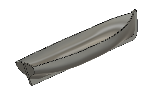
I think this will kind of go full circle. Long before plastic kits even existed, people were making models. Today, we call it scratch building. Plastic kits came along, with a huge range of models which were more than good enough for their time, and everyone was making them. That supply line is kind of drying up and in any case the quality doesn't match today's expectations. Along comes 3D and, in time, individuals and then companies will produce new kits including of ships that were never available in plastic. Just because we can, whereas previously we couldn't. And at whatever scale you desire. You want 1:700 sir, I'll send that to you this afternoon; 1:100, next week. These are very early days for 3D model-making but people are going to become exceptionally good at it and some will probably turn it into a good business. I rather suspect us oldies like the plastic kits because it's what we grew up on, there's a bit of nostalgia in the mix. I wouldn't be at all surprised if, in 50 years time, our equivalents are hunting out and sharing the files for Fred's HMS Lively or Ville de Paris that he produced in 2030. Ian, I don't think the absence of metalwork and woodwork in schools is really related to health & safety but more about what's current. My daughter did 'design & technology', in which they made things using a laser cutter, cast things using resin and all that kind of thing. Back when I was at school in the '70's, we did the trades, I think in part because that's where many of us were destined to end up. I became a sheetmetalworker, others in my year became carpenters, builders, etc. In the early '80's I could quit a job at 9am and be working again the next day, sometimes even the same day. Nowadays there are hardly any factories or SME's doing that kind of thing. It is sad in a way, but in much the same way as the old guys when I was an apprentice lamented the passing of smithing, which even by then had become a niche, arty kind of occupation. It's as you say, the world has moved on. Anyway, enough of that - for light relief, an extremely bad 3D jolly boat (thanks shipman); In my defence I am doing the 3D equivalent of thinking out loud, just playing around a little to understand how to turn sketches into an extremely nice 3D jolly boat, while sorting out the health and safety side of my printing setup.
- 444 replies
-
- 1
-
-
- Cutty Sark
- Revell
- (and 2 more)
-
Resin kits are bound to be expensive, in the short term at least. It takes seconds to injection mould parts for normal plastic kits and I imagine manufacturers could knock out a batch of a ship, say 500, in a day or two. The plastic itself is probably quite cheap as well. Even with industrial printing kit (cost = £10k or £15k upwards) I suspect the same volume could take weeks if not months to produce in resin. Bringing it down to the home printer level, if I set out to model and sell a complete resin cutty sark (and let's assume by then I had complete mastery of the 3D software on both the design and printing side, which I certainly don't at this point), I think it would take maybe 3 - 6 months to design all the parts and then at least a week to print each single kit. The materials wouldn't cost that much, maybe £100, but you'd be hard-pressed to sell these kits at even £300 - £400 and make any profit. I have no idea what the market is like for mainstream plastic kits but suspect it's much smaller than when I was a boy. Back then, happiness was spending all my pocket money on an airfix spitfire or whatever and, if I was lucky, getting the endeavour for Christmas. But these days I expect it's more about the latest phone game etc. My guess is that it's become more niche, more people like us, who spend months and years on each model and spend far more on the extras than on the kits themselves, so I'm not surprised no-one seems keen on investing heavily in new, large age-of-sail kits.
- 444 replies
-
- 2
-
-
- Cutty Sark
- Revell
- (and 2 more)
-
Well done indeed Bill. That's two of the three major milestones completed in a year, which is extraordinary.
-
Well, that's spoilt my day, that was exactly my plan for when I get that far.😝
- 481 replies
-
- 2
-
-
-
- Cutty Sark
- Revell
- (and 2 more)
