


Kevin-the-lubber
-
Posts
1,233 -
Joined
-
Last visited
Content Type
Profiles
Forums
Gallery
Events
Everything posted by Kevin-the-lubber
-
 I think your wife is on the money here, Bill. Even zooming in, this is really hard to spot and even harder for a viewer to realise it's a small mistake rather than a natural artifact.
 -
Good point. It reminds me that I need to shift my FDM printer into the garage alongside the resin printers, as I plan on doing a lot more FDM this year and I doubt the fumes from even PLA or PETG are totally harmless.
-
Is your printer enclosed? If so, it might be worth giving ABS a go, as I believe you can smooth the surface with a bit of acetone. I haven’t tried this myself, keep meaning to make an enclosure and try ABS again, previously I couldn’t get it to stay on the plate.
-
I hadn’t realised Discovery now is so different. I guess that’s the story with most ships though, they are constantly modified. There is a tiered walkway inside the victory scaffolding that allows an up close view of parts of the framing and what they are doing restoration-wise. Also, chances are it will be very quiet at this time of year - but also, pretty cold. Good luck with the interviews. I’m so glad that stuff is now behind me!
-
Perversely, you have both made me feel much better! I caught something a couple of weeks back and can't believe how quickly it burrowed down into the pit of my lungs. I thought it was just me but it sounds like this virus is everywhere, and a nasty, vicious one to boot. I started antibiotics yesterday and am already feeling a whole lot better. I'm looking forward to seeing what you come up with Marc. Even though I haven't really experimented with rope coils other than the odd bit of messing around, I think they are one of the things that can bring the ship alive and make the model convincing, especially if they drape or lie like real rope. Sails are much the same, and every so often I have a brainwave and try another experiment. Sadly none, so far, have proved successful.
- 2,699 replies
-
- 4
-

-

-
- heller
- soleil royal
- (and 9 more)
-
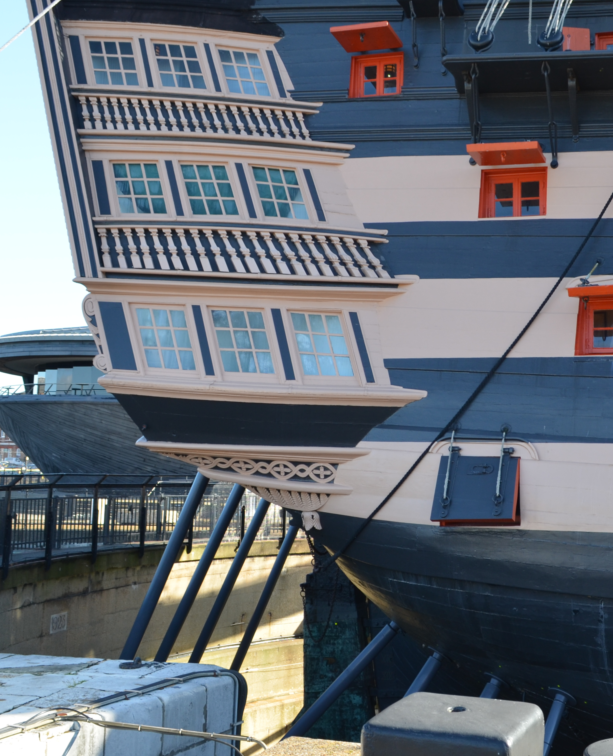
The Victory inside makes for a very interesting visit but be aware the ship is almost entirely enclosed in scaffolding and wrapping right now, with all the outer planking, masts and rigging removed. The stern and quarter galleries are still intact and viewable. I made a mental note that when I next return, to focus more on the Warrior, as I always seem to leave too little time for a really good walkthrough of this ship, which I have vague ideas of modelling one day. You didn’t mention the Cutty Sark in London so I guess you’ve either seen it or aren’t interested. Have you thought of a day trip to Dundee, to see the Discovery in person? It’s very do-able, Stansted (nearish to Cambridge) to Edinburgh return flight, 1 hr drive in a rental. Probably not much different cost-wise to visiting Portsmouth.
-
Most of the stuff I've printed in filament has been for outdoors and unpainted: all of it is still doing fine 4 or 5 years on, having had constant exposure to sun, wind, rain, snow, bird poo, squirrel warfare etc. Originally I used PLA, tried ABS as I wanted the flexibility, but couldn't get it to stick so switched to PETG which is fine for just about everything I make. I am starting to see PLA products being sold in shops now and recently read an article on a factory that runs something like 2000 FDM's churning out kids toys, so personally I don't have any real concerns about the longevity of filament prints. In fact I'd be happy to hear that it does start to crumble after 20 or 30 years as my one reservation about 3D is that I'm adding to the plastics mountain. Not by very much, but it all adds up, doesn't it. Resin is a different kettle of fish. While here again I've got some extremely finely detailed prints that have sat unpainted on my windowsill for 3 or 4 years without any apparent decay, for end product I would always paint them as this acts as a UV barrier (or so I read). That even extends to tiny blocks, where a holy grail seems to be to make them so they look good enough without paint (perfectly do-able, but a different discussion). I'll still paint. I'm not sure anyone knows, or if they do, is willing to say, how long resin objects will remain as good as new. My view is that anything I print in resin is going to end up on a model of some sort, which if it's worth keeping, will probably be kept in a case, out of the sun, and get very, very little post-assembly exposure to UV. While this is not at all scientific, I'd be surprised if it didn't last decades. It would be nice to leave a legacy, but nicer still if that had a relatively short lifespan, for the same reasons as above.
-
I agree, the machines are tools, same as lasers and CNC routers & mills, and so on. But 3D production can easily become the principal method, as is the case with my stuff. I guess it's down to the individual to decide how far they want to go, but my own experience is that it sucks you in. Not that I regret that, I willingly jumped in with both feet and would do the same again. While writing I just wanted to add something - when I first got into 3D I assumed it would be a huge time saver, that I'd be able to knock parts together in a jiffy that would take hours or days by hand. There's a grain of truth in this, you do get far faster as your CAD and printing skills develop, but my experience has been that it often takes considerably longer than making by hand if you're designing the thing from the ground up.
-
I don't think either of you need feel too envious - having seen the work you each do, I'd swap my printers (well, some of them anyway) for your abilities any day. 3D is brilliant, but probably not quite as fulfilling as doing it all by hand.
-
I'd certainly agree with that statement! Gary, you're quite right that it's a rare opportunity to see the framework of a ship like this, which is probably invaluable for people like yourself and Dan. Me, I'm a bit shallow, I like shiny, pretty things and would rather have all the nice bits back where they belong 🙂. It grieves me that I probably won't ever see the ship with the rigging back in place, but I do enjoy wandering around the inside on a quiet day, so will probably go back down later this month while all the kids are back at school.
-
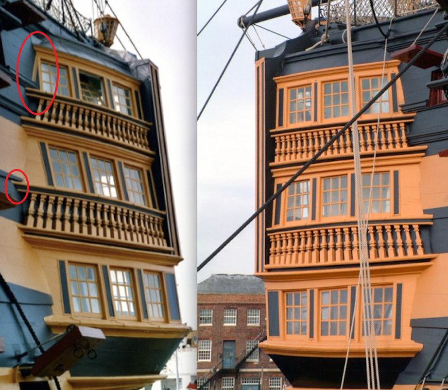
The differences tend to be fairly small but there are quite a few of them. I'm only noticing it as I'm reworking this area at the moment and was having moments where I thought I was going mad, through seeing things on some photos that are different to what I thought I saw earlier (because they are on different sides)! But as you say, all those refits/repairs would explain it. Poor old lady - she's once more looking a bit like that McGowan photo. I still have a 'free' visit to take, as tickets are good for repeat visits within a year, but there's hardly anything left of the exterior right now. All in a good cause though.
-
Dan, I'm sure you'll know the answer to this: was the port side quarter gallery rebuilt during that renovation? It is slightly different to the starboard side. I love what you're doing here, the ship does look a little sad and mistreated.
-
If anyone asks, just say, in a tone that brooks no argument, that sailors were extremely small back then and didn't need large windows. And then send the ship shooting across the lake 🙂
-
How interesting! The same 'problem' is present on the Victory, but not the solution, and you're right, it's absence does detract a little from an otherwise very elegant bit of architecture.
-
It's worth giving the 0.4 a whirl as well, as you're unlikely to be wanting narrower line widths and you can set the layer height to superfine. The smaller the nozzle, the more likelihood of blockages and first layer adhesion problems. The 0.4 seems to be the sweet spot, which I guess is why every printer under the sun comes with that as standard.
-
Oh yes, of course you did. You should be able to print some pretty small, finely detailed items even with the 0.4mm standard nozzle and finer still with a 0.2mm. I printed my original Victory side entrance steps on my filament machine.
-
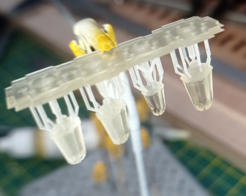
How about filling them near enough with a clear epoxy glue, or anything else that sets more or less clear, leaving a very slight recess. Then put a little dob of clear enamel in the recess. This photo shows, on the left, objects printed with transparent resin (the layer lines cause opacity) and on the right, the same but after I brushed on a little clear enamel. As I needed the enamel to be watery thin, I just sprayed some from a rattle can into a little receptacle. How are you getting on with the Mingda?
-
Ian, in case it’s of any use, for the veneer deck on the Cutty sark I split this into 5 sections by zig-zagging the cut to follow the plank lines. The joints are virtually invisible. The key was to set the kerf offsets right for each orientation of line. This method is a little tricky with very thin veneer as it needs sheets to be near enough dead flat, but should be fairly reliable for 1/16”. (Which has got me thinking….). I subsequently found (via YouTube) the method of lasering pieces (using Lightburn) that are too long for the bed, using lasered datums. It’s fiddly and I haven’t used it for decks, with their ultra fine tolerances, but it worked a treat for some big, crafting stuff I was doing. But if you are using a library laser maybe there are limits to how much you can control the cutting? Are you printing the portholes?
-
Cruise ships seem to currently be havens for nasties like norovirus, probably (I guess) because they have such a huge number of people in a relatively small space and an awful lot of sites such as stair bannisters that lend themselves. Anyway, aside from the norovirus, what was the QM2. Asking for a friend, who likes cruises… The model is looking great, I’m enjoying watching you bring this together. Happy Christmas, hope 2025 is a great year for you.
-
Italy - me too, twice this year, though not as far south as you went. Turin first, in the spring to visit a friend, then an interrail redux from Milan to Rome over a two week period, via Cinque Terre, Lucca, Florence, Perugia and Spoleto. I don't think I'll ever tire of Italy, though I'd take Turin or Perugia over Rome every time. I'll also do the train thing again, found it much less stressy than driving and ridiculously cheap. Nice work on this old boat. It looks like you did a pretty decent job first time round, and I love the note. It's a bit like finding old newspapers when you lift floorboards, or messages on walls when you strip very old wallpaper. I'm back to finishing off the stern on the Victory that I parked 3 years ago. As I'm sure you're finding with this project, everything's a little easier with a bit of added experience and I think I might make headway now. Happy Christmas to you too, I hope 2025 turns out well.
-
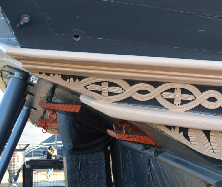
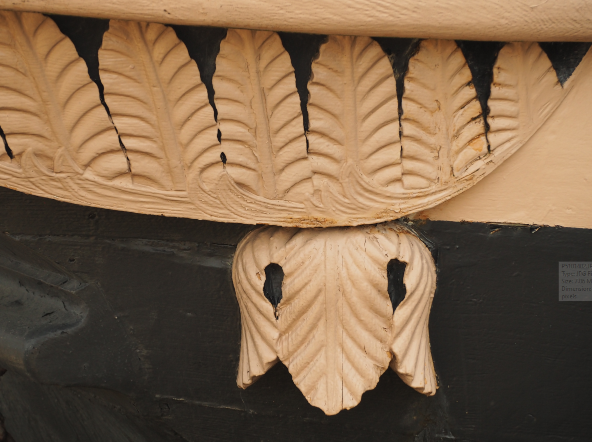
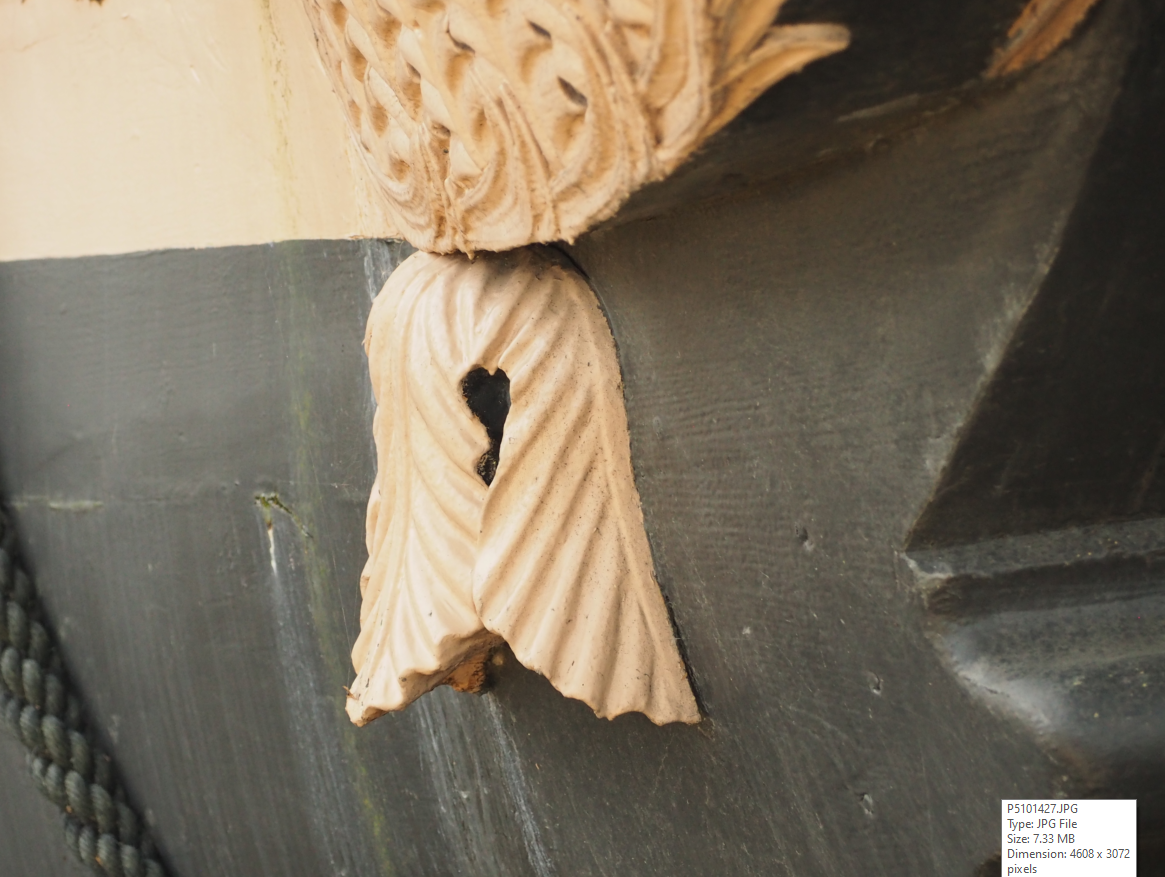
You may be on to something there, see below. There are also numerous plugged circular holes at each end of the counter as well as a few below it. Though none, including the one in this photo, that look big enough for the purpose. Mark, I accidentally deleted the important bit in my earlier post: what you're doing in wood and by hand is extraordinary and extraordinarily beautiful. While it's erroneous to think that CAD makes everything simple (I have spent many hundreds of hours on the Vic stern), it does reduce the task to solving a set of geometrical problems and then making the software do one's bidding; but while we converge in the design phase, when you have to turn the designs into shapes by hand, I do more or less get a free pass and only need to hit 'print'. Even though I can see the shapes in my mind and even on the screen, I'm not at all sure I could make these by hand. And also, it's really encouraging to see that you've been working on this for years and years! I mean that in a nice way of course, that it gives me a bit of belief that I will get there eventually.
-
There is a lovely bit of scrollwork at the base of the Victory's quarter galleries, as per the photos below, terminating in an inverted, 3-leaf, semi-circular 'thing' which doesn't seem to have any particular emblematic significance. I'm wondering now whether the 'thing' is actually an ornate pipe cover. Though the photos don't show this, I'm 80% sure it's hollowed, as this is how I subsequently replicated it, based on my first photo-visit, and I must have had a reason for that. I'm also fairly sure it's big enough to conceal a large diameter waste pipe (maybe 3" - 4") and is placed at the lowest point of the QG, so well situated to get a natural rinse from the sea from time to time 🙂. I'd have thought chamber pots would have been a risky business as the steward would have had to traipse through the day cabin (mind the rug please) within one of the 'rockiest' parts of the ship, all the way up to the heads, another bouncy bit of maritime real estate. Fine on a nice calm, sunny day off Malta but I wouldn't fancy my chances in the Bay of Biscay with a lively swell. By coincidence I'm (re)working my HMS Victory QG's, picking up where I left off two or three years back. Briefly, I'm using 3D modelling to make a better stern for the Heller 1:100 kit and the development process is very similar to yours, Mark, minus your meticulous research and model-making skills.
-
Beautifully done, John, and I hope you'll keep notifications switched on for when some of us want to ask questions.
- 106 replies
-
- 1
-
-
- Soleil Royal
- Ship-of-the-line
- (and 2 more)
-
Sorry but I have no idea how you’d do that.* If I wasn’t told otherwise, I’d assume the draughtsman for that picture had both the photo and a lines plan or similar, worked up the latter in CAD and married the two together for the picture. * long shot: if the Penguin was 3D scanned, the scan may have included skin photos and it is relatively straightforward to slice the scan output to get those station lines. But that doesn’t help you with your problem.
