Rik Thistle
-
Posts
804 -
Joined
-
Last visited
Content Type
Profiles
Forums
Gallery
Events
Everything posted by Rik Thistle
-

Drafting
Rik Thistle replied to mangulator63's topic in CAD and 3D Modelling/Drafting Plans with Software
Before CAD, the foolproof way to visualize a project in 3-D was to construct a physical model (aka Space Model). I worked in avionics design. Once we had hardened down on the sizes of the LRU boxes, mounting racks, cable harnesses, cooling ducting etc (LRU = Line Replaceable Unit) we would hand the draught layout drawings to the model making shop. They would make wooden versions with real connectors, and then we would fit the wooden models + harnesses, cooling etc into the actual aircraft. This never failed to reveal certain issues and conflicts with existing structure, access etc. Model shops were a crucial part of the design process. And the people who worked in them were top notch. Richard -
Drafting
Rik Thistle replied to mangulator63's topic in CAD and 3D Modelling/Drafting Plans with Software
The MGB drawing is ink on mylar from 1980. The above is fit for framing and mounting on a wall. A very nice drawing and interesting subject matter. It would work well from A4 to A0 sizes. Richard -
Drafting
Rik Thistle replied to mangulator63's topic in CAD and 3D Modelling/Drafting Plans with Software
Tim, Firstly, yes, thank you for starting the thread...it's brought out a lot of useful knowledge and (somewhat similar) views on drafting/draughting from both sides of the pond and around the world. Secondly, 'Home Economics Class was mandatory for both boys and girls' - in my secondary school it was optional IIRC, and not many lads took it. It probably would have been of great benefit if it had been mandatory for girls AND boys 😉 Richard -
Drafting
Rik Thistle replied to mangulator63's topic in CAD and 3D Modelling/Drafting Plans with Software
Dr PR, Today DesignCAD is considered to be a "hobby" program, and it lacks some of the bells and whistles of more expensive programs. But it is still a very capable 2D and 3D drawing program. Considering it costs about $100 with free bug fixes and technical support, and it has a great free user Forum where you can ask experienced users how to do things and solve problems, it is a tremendous bargain. Thanks. I'll read up on DesignCAD...$100 is well within my 'budget' range 🙂 Richard Later: I see DesignCAD is sold by TurboCAD, who I recognise. Seems it is now $60 ... DesignCAD 2D 2020 https://www.turbocad.com/designcad/designcad-2d.html ...and it's not subscription! I'll watch some YT videos on it. They also have a 3D package DesignCAD 3D Max 2020 and TurboPDF v4 Bundle https://www.turbocad.com/designcad/designcad-3d-max-2020-and-turbopdf-v4-bundle.html at $200 which is kinda within the realms of 'well maybe, one day' budgeting. I'm assuming the two packages would use the same interface design....that is as important as anything. -
Drafting
Rik Thistle replied to mangulator63's topic in CAD and 3D Modelling/Drafting Plans with Software
Hank, Hope this has provided sufficient inspiration and so forth, Yes, and then some 😉 'Maker Clubs' was what I was thinking of when I said 'club'. Yougsters exploring new ideas and gadgets...and good for them. I imagine they will use CAD even if only for 3D printing. But with current movement restrictions I suspect it will be at least summer time before I dare enter a room full of strangers. In amongst the discussions in this thread I was actually looking at Spark. More investigation required. 2D and 3D programs...yes, it might be that getting a freeware version of each it the way forward from a cost perspective but no doubt they will be made by different manufaturers so double the learning curve. I've got all the board drafting tools necessary and was trained to BS308. I still find it very easy to use them to do accurate scale drawings. Unfortunately my drawing board is A2 sized and I am well over 6'...so no sleep overs on there 😉 Good chats on here, as usual...and maybe enhanced even further by the time of year. All the best, Richard -
Roger, “She has been out of the water for several years and is completely dried out.” Yes, I remember them saving the Mary Rose (?) timbers but keeping them constantly sprayed with water, not to save any seals I imagine, but to stop shrinkage nonetheless. I assist with maintenance work on my friend's near 60 yr old wooden framed aircraft and I never fail to be impressed by what an amazing engineering material wood is...as long as it is looked after carefully. Richard
-
Gunther, Basically there is a flexible 'gasket' between each plank to stop water ingress so some swelling or shrinkage shouldn't be a problem because they handle it in the design/construction. Ah, OK, that makes sense. Thanks. Richard
-
Drafting
Rik Thistle replied to mangulator63's topic in CAD and 3D Modelling/Drafting Plans with Software
Terry, Currently using Coreldraw X7 for drafting ship plans. If I ever get in to scratch builds (and I would like to, eventually) then maybe...but at the moment £700 = two good ship kits ... however one day I'll maybe have to bite the CAD bullet. There were also some comments earlier on about investing in CAD training...so perhaps I should consider joining a CAD club or do night school to get a feel for CAD first. Anyway, thank you for the comments. Richard -
Drafting
Rik Thistle replied to mangulator63's topic in CAD and 3D Modelling/Drafting Plans with Software
I miss seeing the draughtman's dance: doing a few lines, standing back to review the work, stepping forward to fix or add to it. 😉 I did that dance for a few years. Then we moved to a more compact room and were supplied with draughtsman's chairs...but you can't work an A0 sized drawing from a seating position so we always ended up standing at the drawing board and then turning round and sitting at the design desk. And of course, I was younger then and standing for hours was not a chore. 3 or 4 companies and a number of job changes later, I retired early, and just at the time they were clearing out the 'old' drawing office...so a number of draughtsman's chairs were up for grabs...and I got one. It's been in my shed for years and I wouldn't swap it for any other chair...it's a masterpiece of functional design...robust, comfortable, stable, height adjustable, a ring to put the feet on etc...wonderful. Richard -
Drafting
Rik Thistle replied to mangulator63's topic in CAD and 3D Modelling/Drafting Plans with Software
Rick, Thanks for the feedback. The closest thing I can think of to a "one size fits all" package would be Solidworks. I have tried many of the "usual suspects"; Delftship, Autocad, Revit, Solid Edge (for more than a year), Rhino, and Catia. On cost/benefit basis, I have found Solidworks beats them all, hands down. Being retired, I can't justify the cost of Solidworks (£7k-£10k ?) but it does look very competent. And, as you mentioned, it takes a fair commitment in 'time' to get up to speed on such software. I'll maybe have to lower my sights and just keep my eyes open. I have tried SketchUp and FreeCAD but none seemed to match my main need for 2D draughting. 3D is a 'nice to have' but not essential at this time. Richard -
Seasons greetings. Health. Wealth. Happiness And to you and your's all also. Although I was aware of the Arctic Convoys I never really knew about them. So I have just spent a bit of time on Wikipedia reading up on them.... strategically very important events and very brave people involved. I found out there were a number of books written and a film made. I will try to find out where this film is available.... https://www.prlib.ru/en/news/684563 Richard Edit: I found this film ... https://www.amazon.co.uk/PQ-17-Arctic-Convoy-Disaster/dp/B00JAI29AM ...it's Clarkson commentating but I think he knows when to be serious.
-
Bob, That's six inches of grain to shrink tangentially and even at a rate of movement of one percent, you are getting close to a sixteenth of an inch, which would be a quite noticeable crack in a model's topsides. Yes, that does make me stop and think. Useful info, thanks. As a non-sailor but ex-engineer how do full sized wooden boats and ships cope with that movement....pumps? Richard
-
Drafting
Rik Thistle replied to mangulator63's topic in CAD and 3D Modelling/Drafting Plans with Software
I was trained in traditional draughting at school and later to the BS 308 draughting standard (now superseded by BS 8888). It used 0.7mm lines for object features and 0.3mm lines for dimension leader lines etc...those different line thicknesses made it easy to 'read' engineering drawings. I keep promising myself I will learn 2D/3D CAD but my heart just isn't in it. I have a desk mounting, Rotring A2 draughting board and all the instruments necessary to quickly and accurately sketch up scale drawings of most things I need to draw. I think one of the main reasons CAD draughting is dominant is that it forms a cost effective part of the digital manufacturing chain, the same chain that is replacing expensive humans at each stage. Other small, but not insignificant benefits of CAD draughting is that A0 drawing storage and A0 printing is no longer required. And 'copies' of drawings can be sent in a second rather than days. I have tried CAD packages but the learning curve seems too steep. If anyone can recommend a cheap, one-size-fits-all package that is easy to learn and suitable for mechanical engineering, ship plans and 3D printing I would be grateful 🙂 Richard -
I hope you find many, many more items to add to keep the build going for another year or two 🙂 Great work, Richard
- 261 replies
-
- 4
-

-
- muirneag
- vanguard models
- (and 2 more)
-
I've got the blue Lowes in my shed for small work, and the yellow Stanley in my study. The Stanley is the one to go for because of it's flexibility and reasonable build quality. The ball joint on mine (bought 7 yrs ago) was tight and rough so I took some Emery cloth to the ball and that fixed it. The Stanley comes with plastic soft jaws and the metal jaws have a groove running the length of the jaw and also a groove at right angles to the first in the centre of the jaw...both grooves are very useful for gripping cylindrical objects. It clamps quickly onto a desk surface (....the Stanley clamping surfaces are plastic covered to protect the desk). For £20 the Stanley is good value ... https://www.amazon.co.uk/gp/product/B001HBS0I0/ref=ppx_yo_dt_b_search_asin_title?ie=UTF8&psc=1 Richard
-
Yes, it is. Just taken from a different angle but mounted in a newer (?) base. The different angle may give another take on the routing of the ropes, but it's not a high res pic. Richard
-
Another pic here .... from https://www.authenticireland.com/blog/aberdeen-aberdeen-prettiest-town/ ...scroll down almost half way. Now set in a larger base. Richard
-
Erik, Congrats on the successful team presentation, and getting back to the shipyard for the festive period. BF 1479 is looking very neat and (in my imagination) keen to get a catch on board ;-) Richard
- 222 replies
-
- 3
-
-
- First Build
- Lady Isabella
- (and 2 more)
-
Hi Glenn, I did say that the fix to be balanced with it looking 'acceptable' 😉 ... but you're right ... it can be a head scratcher sometimes trying to figure out how best to correct a mistake... but I enjoy solving puzzles, so it's another good aspect of modelling. As I learn more about modelling I'm growing my list of ways to fix 'instructions misunderstandings'. Happy days. Cheers, Richard
-
Planking pins/nails
Rik Thistle replied to DaveBaxt's topic in Building, Framing, Planking and plating a ships hull and deck
Dave, A member on here kindly advised me that putting the nail through a scrap piece of wood (say, planking off-cut) first, then tapping the nail (plus scrap) into the plank/bulkhead was a good way of making it easy to extract the nails once the PVA glue had set. The scrap keeps the nail head about 1mm or so (scrap thickness) above the glued plank so it is easy to jam a lever into the scrap and extract the nails. The scrap also spreads the clamping load over a wider area than the nail head as the glue dries. Richard -
Probably still plenty of thickness to fill, sand, and repaint the hull. Since posting, I've sanded the white paint back a bit and added some filler. And repainted - it's now looking not too bad. Nice job on the Wales, remove and replace is a way of life for me... 🙂 Yes, 'fixing' becomes part of the build process... ie realising I've messed up and, once I get over the 'doh!' moment, enjoying figuring out the least painful fix balanced with it looking acceptable. Richard
-
Restoring large model of WWII Battleship USS Alabama
Rik Thistle replied to Rik Thistle's topic in Nautical/Naval History
Yeah, it would need to be quite light as you say. But I suspect there must be a steel beam of sorts running down the length of it to stop it breaking it's back when being moved. Then build everything around the beam. I wonder if it was a shipyard apprentices' project or maybe trainee naval architects? The fact that it is being refurbished in a naval shipyard give me the impression it was originally made to a decent standard. Richard- 3 replies
-
- 3
-
-
- Alabama
- parade model
- (and 1 more)
-
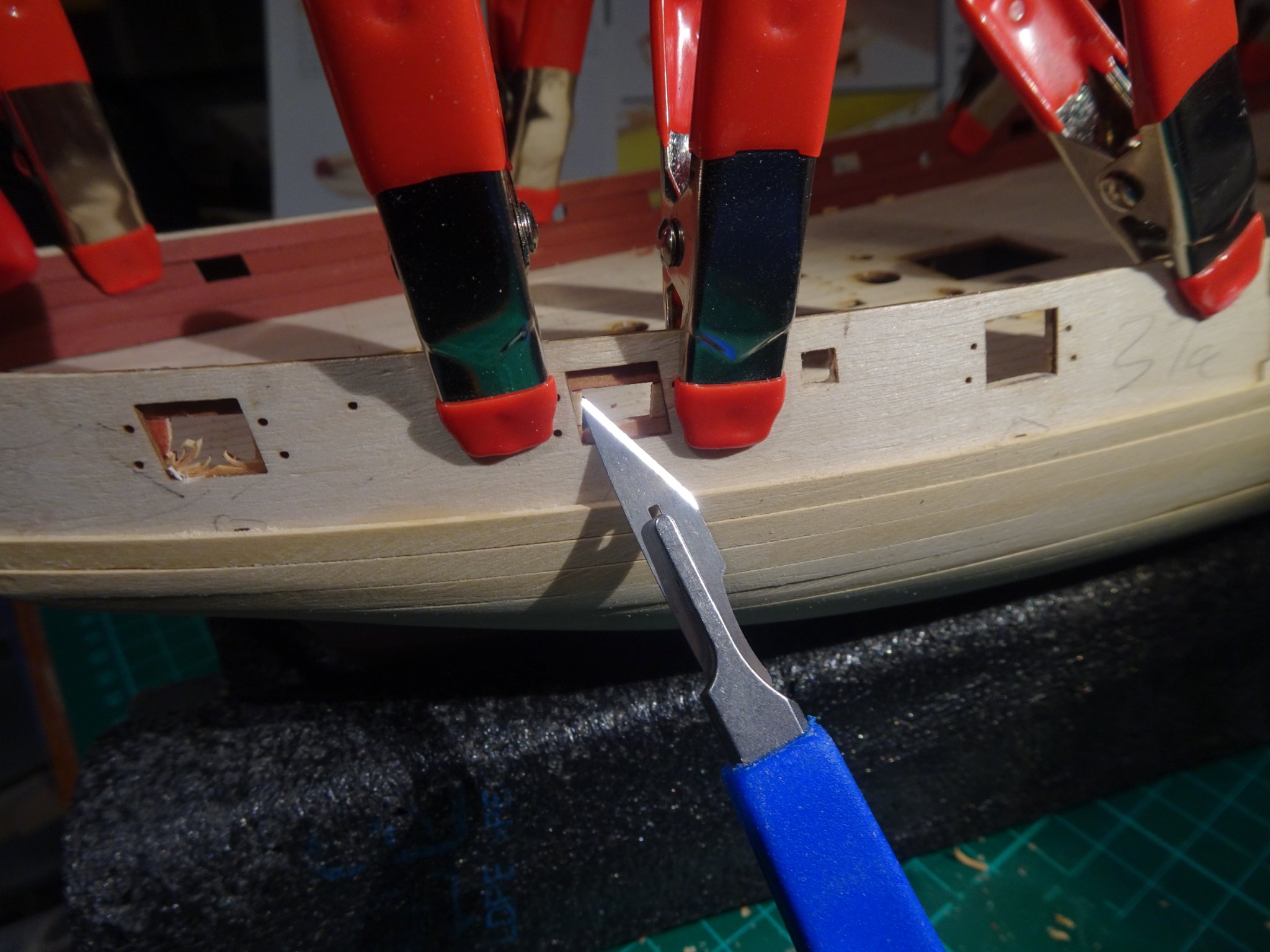
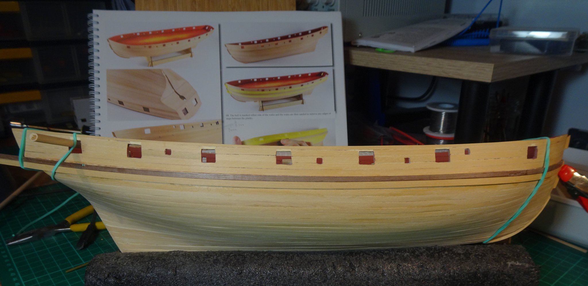
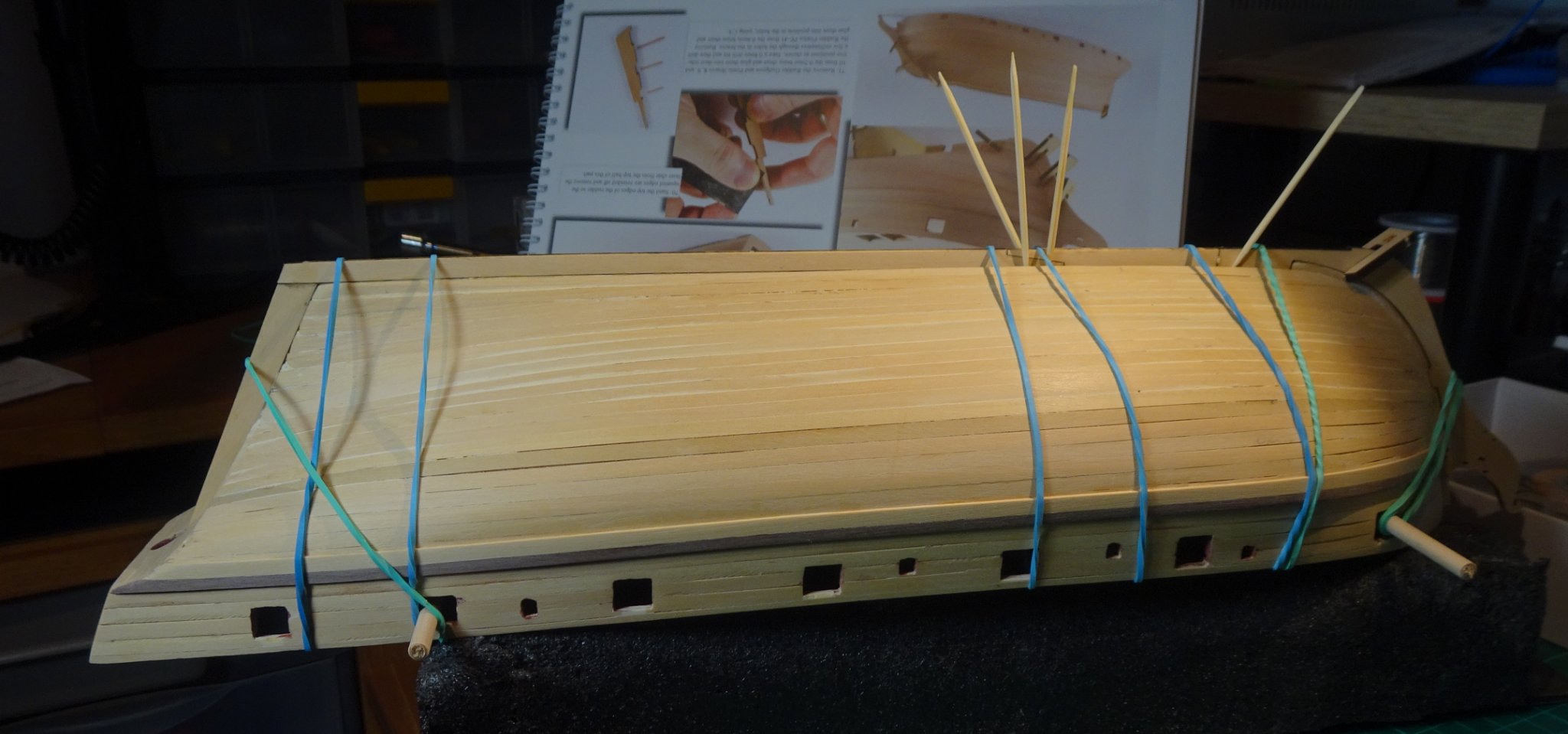
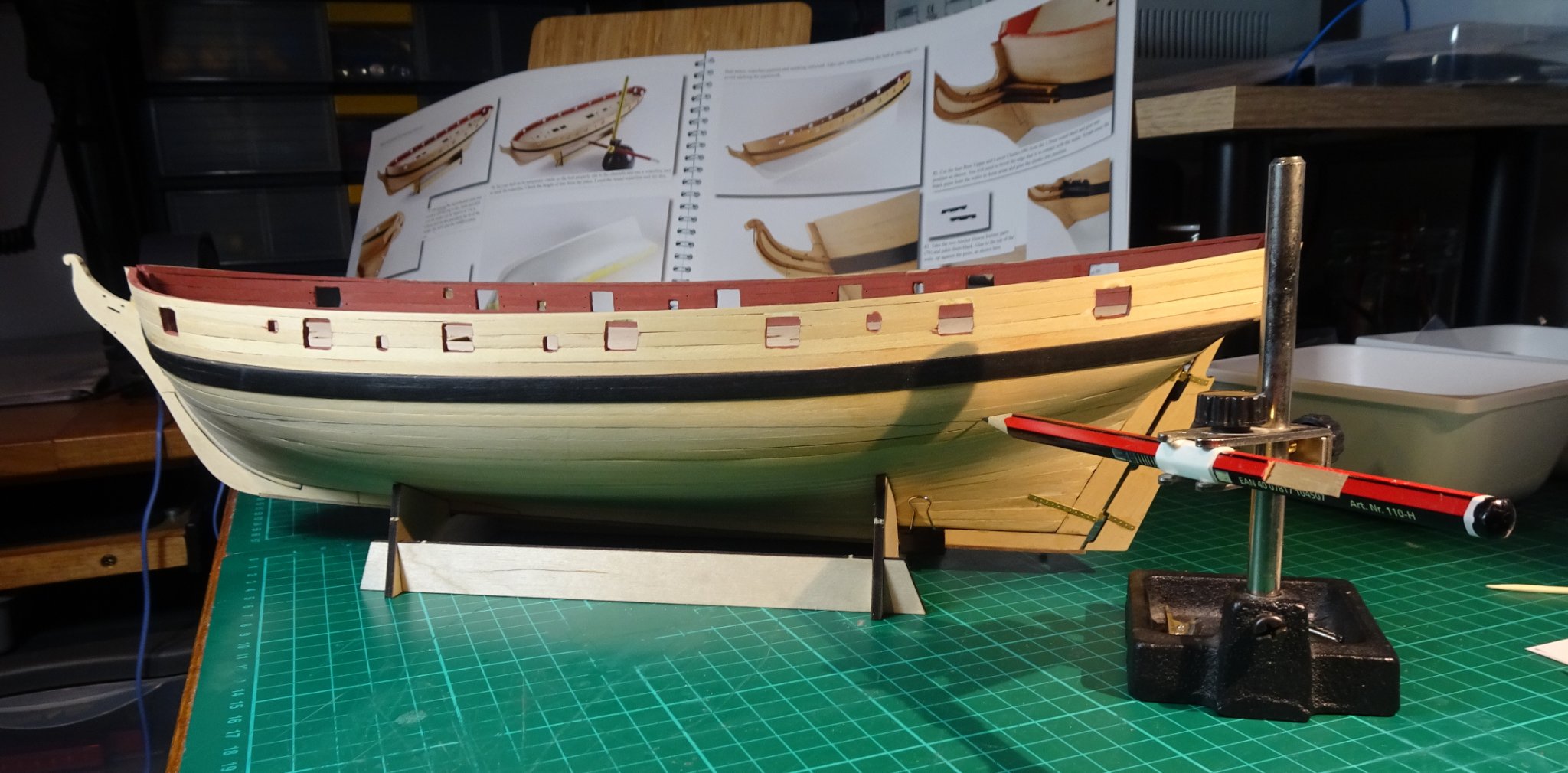
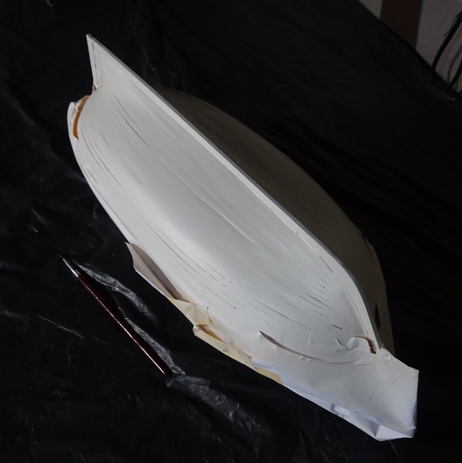
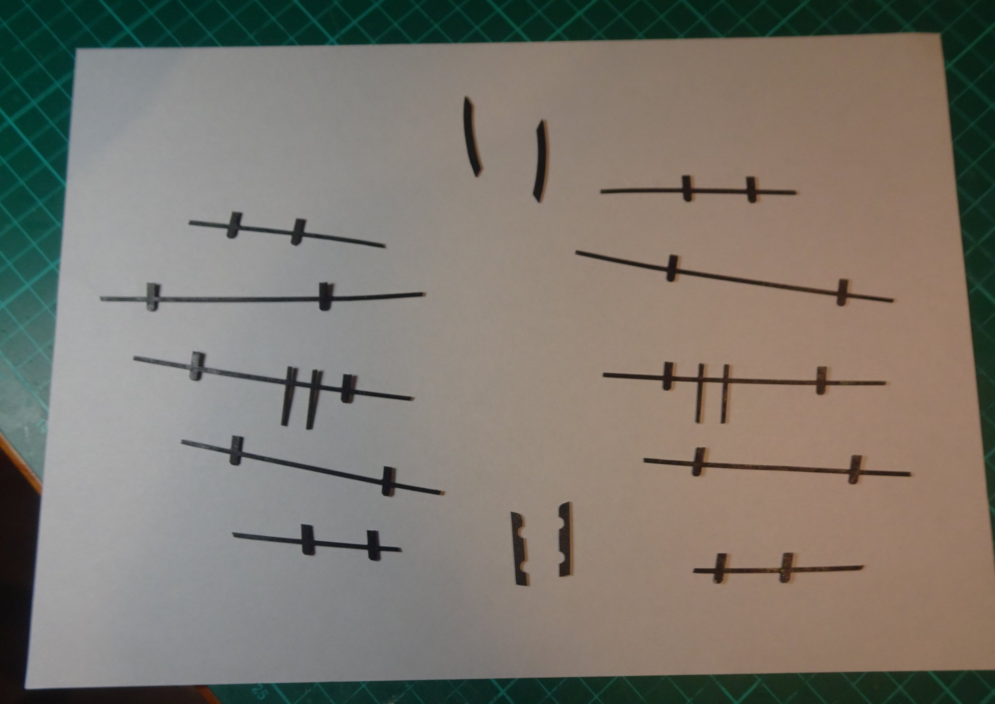
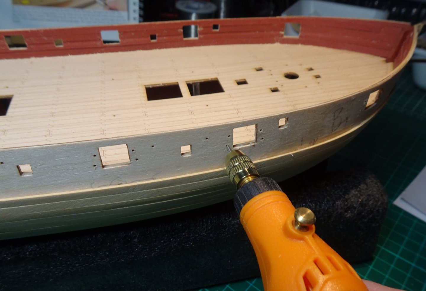
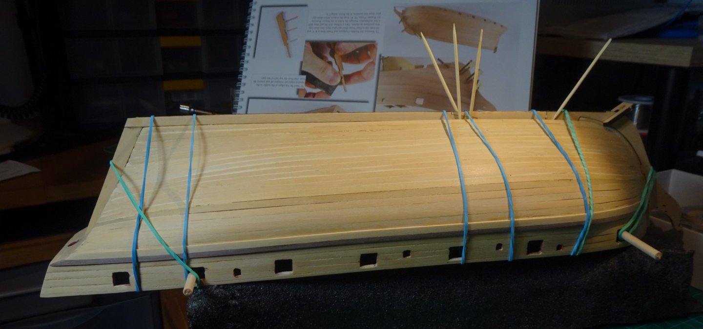
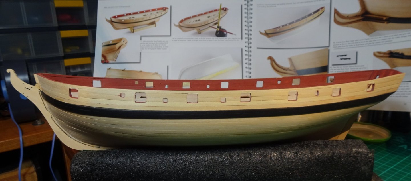
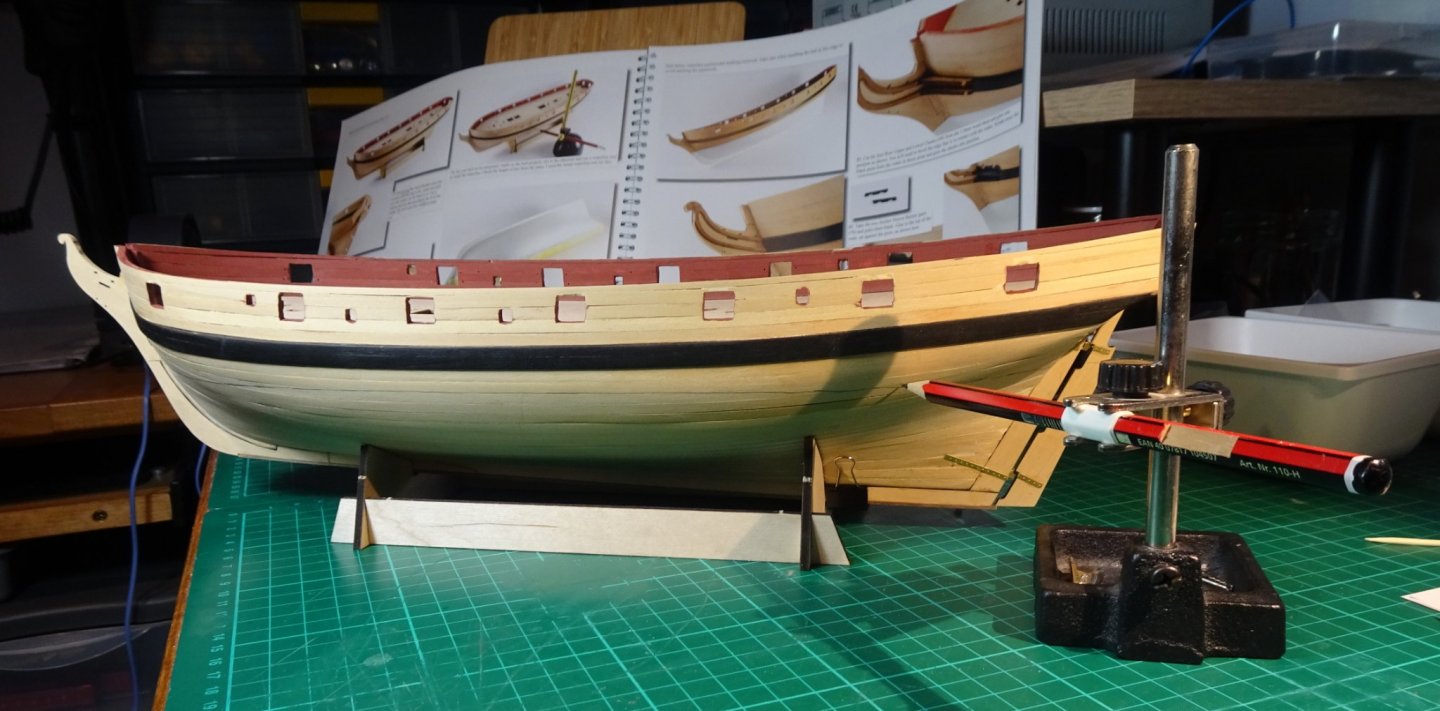
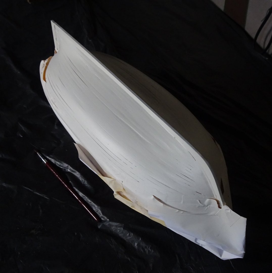
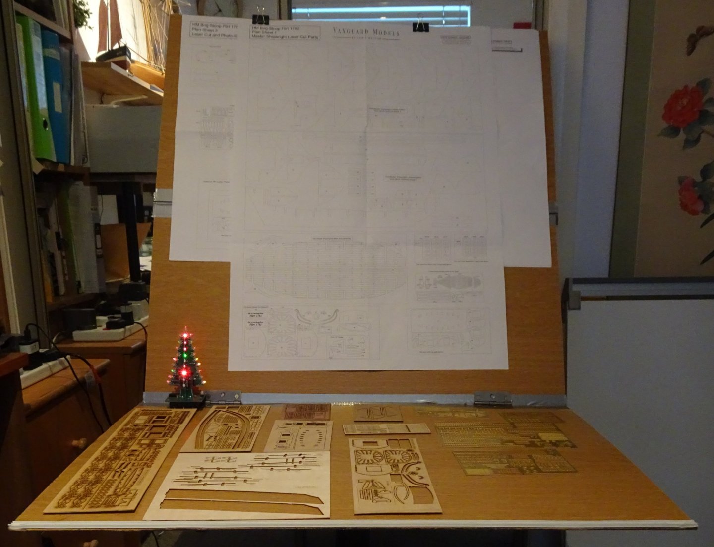
Hi all, Work continues on Flirt - two steps forward, one step back....due to someone not reading the instructions properly. Below - Clearing out the holes in the bulwarks after the internal planking was fitted. The Banggood 'dremel' is really quite useful, and it's rechargeable battery lasts an acceptable amount of time. The internal planking needs a little bit of 'filling' plus a bit of touchup paint. And hacking out the gunhole ports with a scalpel blade and then a needle file to smooth the sides off. Yes, the stain (now difficult to see after major clean up) above the wales looks like someone has mistakenly glued the wales above the pencil marks rather than 'up to' the pencil marks. Also, I couldn't find the 3mm x 1 mm wood so used some walnut I had in the 'stores'. Below - Keel being glued into position. The toothpicks are wedges to make sure the keel lies centrally. Yup, there is a handy gap (don't ask) between the keel and the garboard planks for the toothpicks to dig in to...filler later removed those gaps. Filler is great stuff 😉 The MDF Pegs for aligning the keel parts are necked at their ends... so I couldn't get them to slide on to the keel parts. Not sure what I was doing wrong here? Wales painted black, and a bit of general tidying up done. Below - Marking the waterline with my home made marker. Note the bulldog clip, bottom right on the keel to stop the hull sliding about in the base. Hull painted white. Gaps showing between the planks. They look worse than they actually are, but I may add a touch of filler and repaint, or more likely hand paint in the gaps at a later date. I don't mind the planks showing since it indicates what the structure is but the gaps mustn't be too obvious. Whilst the white paint dries, the rail and timber posts were painted black. There are a lot of small parts that need painting black, yellow etc. Below- After getting fed up continually digging in to the Flirt box for wood/brass sheets I decided to lay them all out my home made drawing holder/work platform. A Banggood Christmas tree has been added because...well, it's that time of year. Nope, I'm not on a commission from Banggood 😉 I think that's all for this post. Flirt seems to be progressing very slowly. The hull planking did take quite a bit of time and I lost a bit of momentum, but I guess it's not a race. Catch you all soon, Richard


-
Whilst reading 'USS Bonhomme Richard on Fire' https://modelshipworld.com/topic/25040-uss-bonhomme-richard-on-fire/?tab=comments#comment-776194 ...I ended up on 'VIDEO: Navy Restoring Unique Parade Float Based on WWII Battleship USS Alabama' ... https://news.usni.org/2020/12/16/video-navy-restoring-unique-parade-float-based-on-wwii-battleship-uss-alabama ....now that is a large model! Was the model made in an actual Naval shipyard...I can see it is being refurbished in Norfolk Naval Shipyard? Is it made mostly of wood, or sheet steel? Richard
- 3 replies
-
- 6
-
-
- Alabama
- parade model
- (and 1 more)
-
B.E., I'm not too sure about the intricate workings of the capstan but I think there would be a pawl system on it. Sailing Drifters is a good read, so many snippets about life in a fishing community around the turn of the century, even down to the cost of a pint of ale! I have now bought the sister volume on Sailing Trawlers. Thanks for the reply. Sailing Drifters is an amazing read. The author certainly put his heart in to it. Reading it though is not that easy, as you hinted a little while back, since March just jumps straight in with all the technical jargon of the time - and being a noobie there are numerous paragraphs where it may as well have been written in a foreign language. However, there is a Glossary at the back that I am flicking back and forth to. I'll be sad when Muirneag leaves the shipyard...maybe she'll come back in a few months for a refit? Regards, Richard
- 261 replies
-
- 3
-
-
- muirneag
- vanguard models
- (and 2 more)