BANYAN
-
Posts
5,951 -
Joined
-
Last visited
Content Type
Profiles
Forums
Gallery
Events
Everything posted by BANYAN
-
 That looks really good Michael; not much left now. More room in the workshop - any ideas of what is next? cheers Pat
- 749 replies
-
- 3
-

-
- albertic
- ocean liner
- (and 2 more)
-
ancre Chebece 1750 by Jeronimo - FINISHED
BANYAN replied to Jeronimo's topic in - Build logs for subjects built 1501 - 1750
I very much enjoy following your build log Karl; exceptional workmanship and a joy to behold. cheers Pat -
Stunning work Dave; even at extreme close-up your work is clean and crisp. The rigging is looking very good. cheers Pat
-
HMCSS Victoria 1855 by BANYAN - 1:72
BANYAN replied to BANYAN's topic in - Build logs for subjects built 1851 - 1900
Thanks again for all those that have looked in and 'liked' my latest posts - much appreciated. You're right with that aspect of modelling Eberhard. As frustrating as researching is at times, there is much satisfaction when you resolve such issues. Very many thanks for your kind comments Michael; noting your own work these comments are much valued. Thanks Denis; appreciate your suggestions and the problem you describe is exactly the issue I am experiencing. I have found some good "waterslide" superthin decal paper which is laser printer compatible so I can use TurboCAD to draw up the decals and print them. Is that what you mean by 'decal program'? cheers Pat- 1,013 replies
-
- 3
-
-
- gun dispatch vessel
- victoria
- (and 2 more)
-
Not sure if you have resolved this Michael; but from my 'limited' knowledge this appears to be a HF radio antenna. Some form of 'fan aerial' with four risers (fore/aft and port/stbd) rising to a point at the insulators on the wire stay above (which may be a 'long wire HF aerial'. There are also four legs (horizontal) that form a crucifix shape and connect to the four risers - these were used to form the 'ground plane' for the aerial. One leg of this would have had to have been 'earthed' but cannot make out enough detail to see if the 'loop' bit was the earth or not. The natural cordage may have been used to raise/lower the top of the aerial to the wire stay/wire aerial? This was natural fibre probably to minimise static and prevent 'interference' with the main aerial. Not sure I can make it out but is this in the form of a simple whip tackle? A heavier duty tackle would not have been required I think. cheers Pat
- 749 replies
-
- 7
-
-
- albertic
- ocean liner
- (and 2 more)
-
You have certainly mastered the manipulation of PE Greg; looks great! That shot of the dry fit sure shows how much detail was on these beasts. A wonder you don't get RSI from all that PE folding. cheers Pat
- 405 replies
-
- 7
-
-
- tamiya
- king george v
- (and 2 more)
-
HMCSS Victoria 1855 by BANYAN - 1:72
BANYAN replied to BANYAN's topic in - Build logs for subjects built 1851 - 1900
Thanks for all the likes, and for the encouraging comments Marty and Eberhard. That's a great idea Eberhard, I'll have a poke around online to see if I can find one of those pens - my shaky hands are the real problem as 'discipline' will really be the operative word here :). When I looked at the photo the 'scale ratios' of the companion to the wheel assembly looked wrong. The wheel size is correct but it appeared too low. A prolonged discussion with an engineering friend isolated the issue. I had been working on the assumption that the rapson slide tiller arrangement was fitted to the underside of the weather deck. However, a closer examination of the patent drawings shows it was actually above deck and the rudder head penetrated above deck also. We are now reasonably sure the wheel assembly would have sat on top of a closed in 'box' arrangement that contained the rapson slide and pulleys etc; which would then raise the wheel assembly to the height suggested in the photo posted earlier. This arrangement would then allow the control rods for the propeller (clutch, pitch and locking) to rise to the upper deck also (confirmed by actual drawing of the propeller fit) whereas I had been frustrated with how to 'swing' the tiller arm without impacting these rods. Furthermore, it now allows the fitting of 'Lang's' emergency tiller arm abaft the rudder head without impact on its length as had been the issue by trying to fit into the space/ void below deck - a double win all round A drawing will follow. Surprising how eventually these issues resolve with a persistent pursuit aided by visual prototyping. cheers Pat- 1,013 replies
-
- 6
-
-
- gun dispatch vessel
- victoria
- (and 2 more)
-
HMCSS Victoria 1855 by BANYAN - 1:72
BANYAN replied to BANYAN's topic in - Build logs for subjects built 1851 - 1900
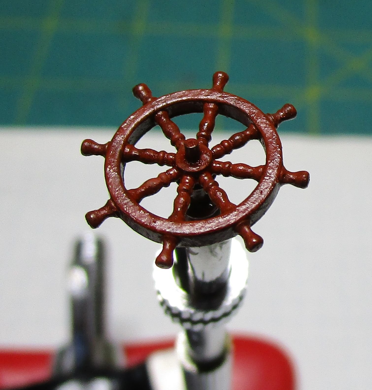
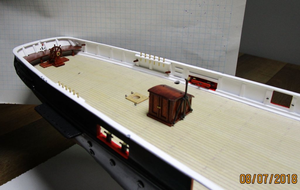
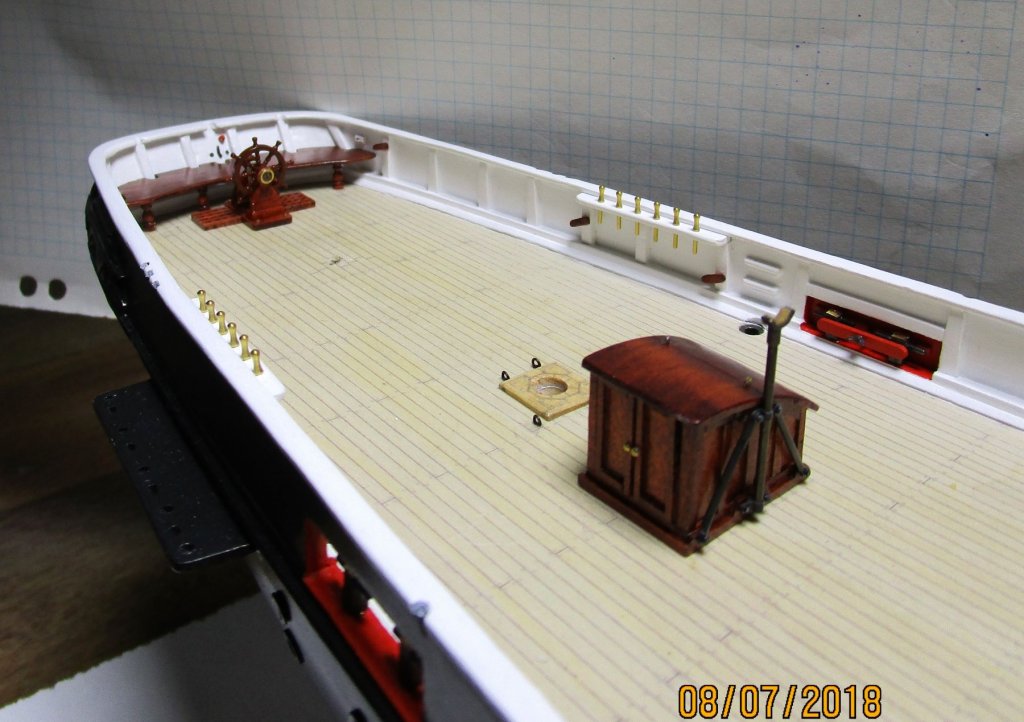
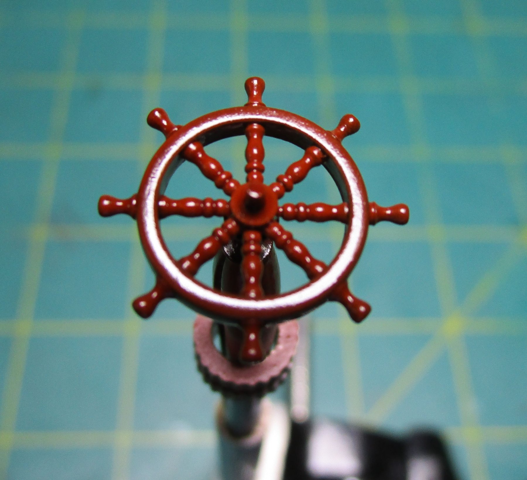
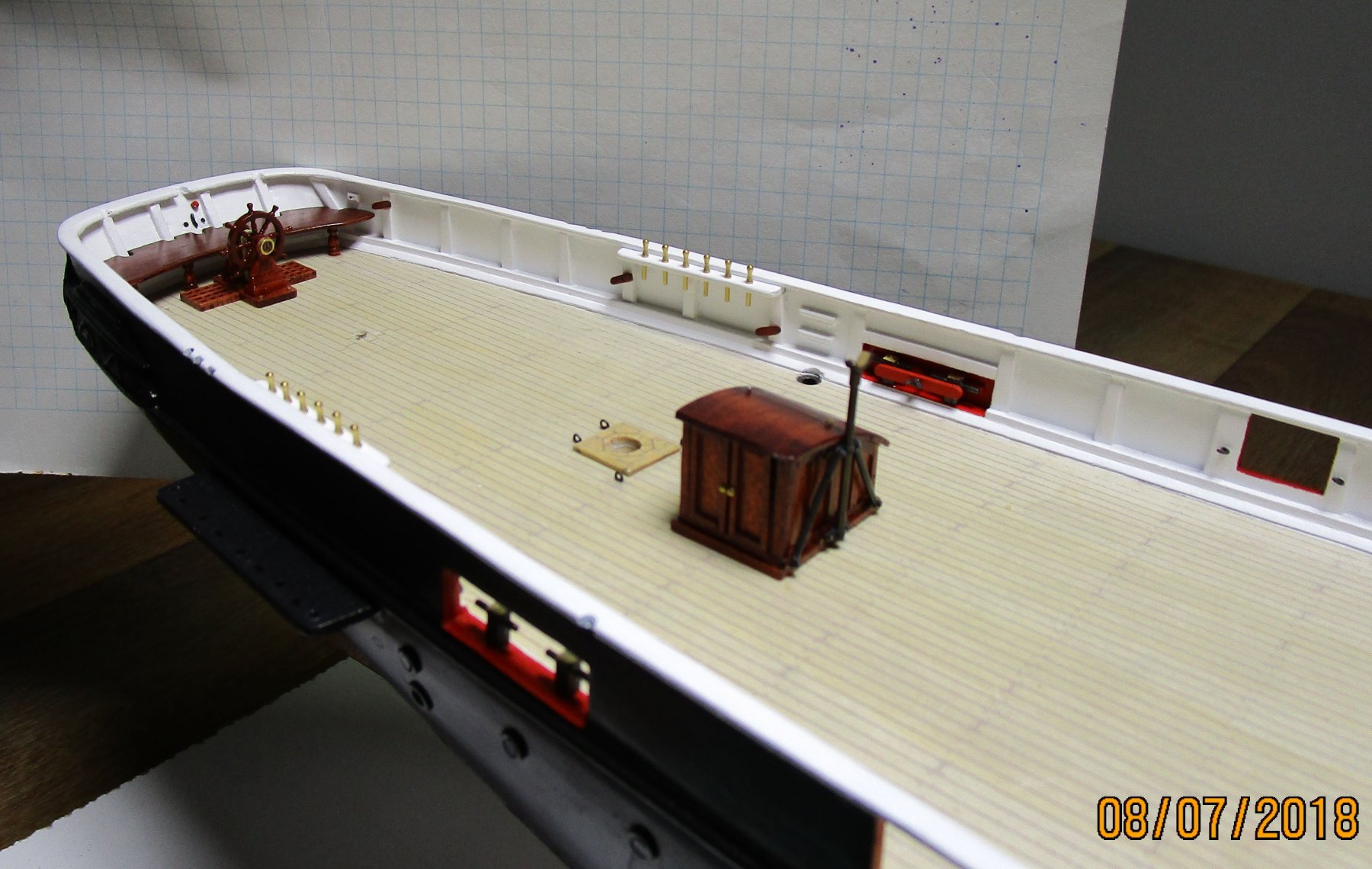
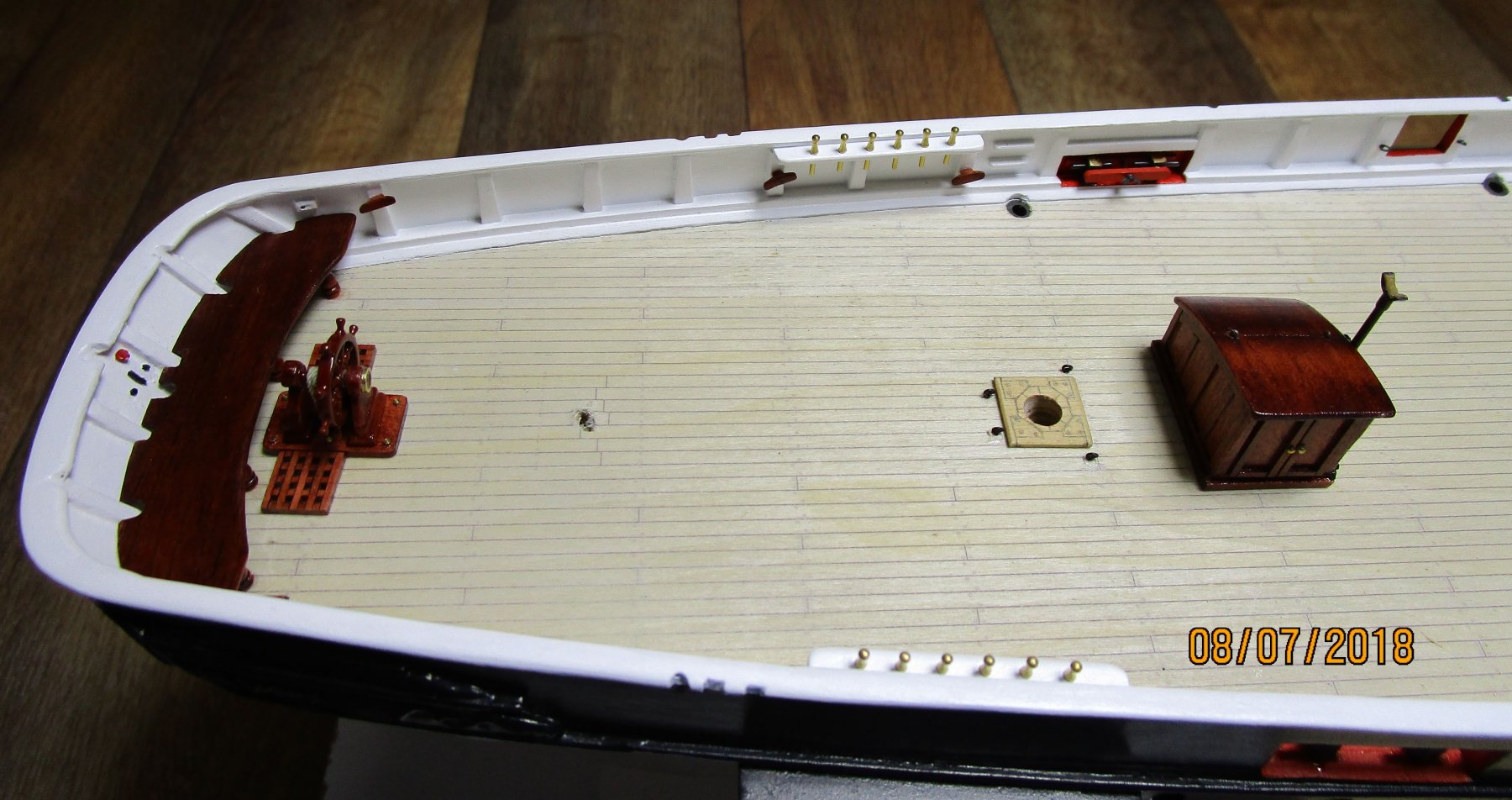
Another small update. After retrying the decals I had two problem; first the colour of the decals just do not show up against the brown (a known issue apparently but I thought I would try), and after trying that I found the wheel had 'roughened' again. I put the latter issue down to using the water on acrylic paint/gloss when trying to apply the decals. The photo show the wheel having been redone - please remember the rim is only 1mm wide and 12mm in diameter (OD). I have decided that even PE will be difficult at this scale (to etch that is) so we have decided to leave this small detail off. i think there is enough detail to make the steering arrangement look OK? Yep - I know - a real 'cop out'. If I get time I may revisit this when I do the PE for the brass work on the skylights. The following photos show the companing and steering position dry fitted. In hindsight, I think we opted for a slightly too large rear bench but it will have flag lockers fitted on top of it either side of the wheel and we needed sufficient width to allow for that. The red 'pull' cord is for igniting the powder via the adapted gunlock on the Common Service Lifebuoy on the transom - this then provided the smoke and/or the flare (night) in the upper pan of the lifebuoy. nThe black handle is a 'twist to release' for the lifebuoy. In later times, these two controls were combined. One remaining issue is to determine what the most probable configuration for the mizzen boom crutch. The boom extends beyond the transom, and in the photograph of the crew on the quarterdeck, it shows the boom, when in its stowed position, lies to 'port' of the ensign staff. Unfortunately, as can be seen from the earlier photo of the wheel, it is impossible to make out the configuration of the crutch support. At the moment I am tempted to have it secured to the transom using the roughtree timber immediately to the left of the centreline and using the back edge of the bench as one of the vertical supports (a hole drilled in the bench). What I cannot decide for this configuration, is whether any supporting struts would have been required or simply a supporting upper bracket near the top of the roughtree timber. The next outboard roughtree timber (with the notch in the rail) is for one of the rear davit arms. An alternative is have the crutch with tripod style support configuration, free standing in front of the bench but I think that would be in the way of the helm (not that the crutch would be there when the wheel was manned). The issue with the first configuration is that the crutch would be in the way of working the boat; but, again the boom, and therefore the crutch, would have had to be moved out of the way before working the boat anyway. Opinions and suggestions eagerly sought cheers Pat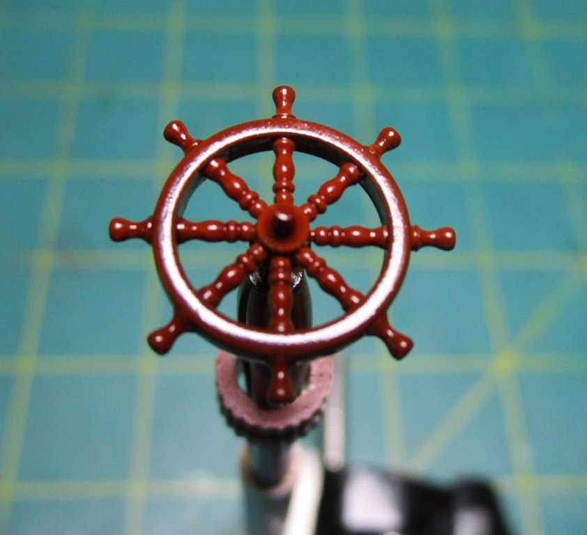

- 1,013 replies
-
- 20
-
-
- gun dispatch vessel
- victoria
- (and 2 more)
-
HMCSS Victoria 1855 by BANYAN - 1:72
BANYAN replied to BANYAN's topic in - Build logs for subjects built 1851 - 1900
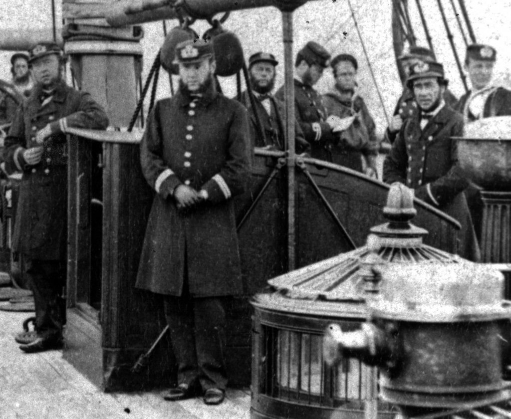
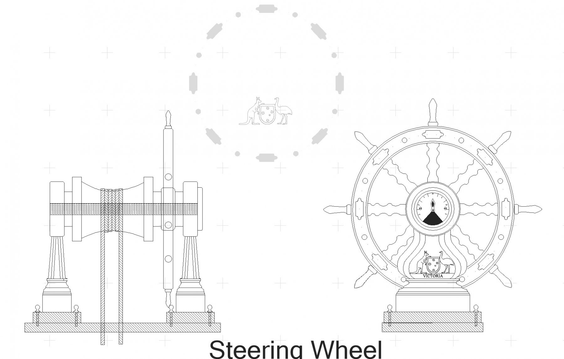
Hi Druxey and many thanks for looking in and your suggestion. Unfortunately, as shown in my less than adequate drawing below, the wheel did not have a brass ring on the rim, but rather a series of plates as evidenced in the photo (this is a highly zoomed extract of a photo of some of the Officers and Crew on the Quarterdeck taken in 1868). The drawing shows the graphic I have used for my decals also. I will remember that technique as for my Endeavour I used a twin blade cutter (knife) in a compass to cut some thin brass (shim) which proved problematic. To explain the shape of the standard I have adopted, I based the overall shape on the requirement to have a carving of the coat of arms carved into it. This is the most probable shape that serves and is similar to the standard as shown in a contemporary model of a wheel and standard held by the NMM. Unfortunately the standard cannot be made out in the photo. I have bit the bullet so to speak and removed the old paint from the wheel and repainted it so that I have a new flat surface. I will have one more go at the decas before giving up on them. cheers Pat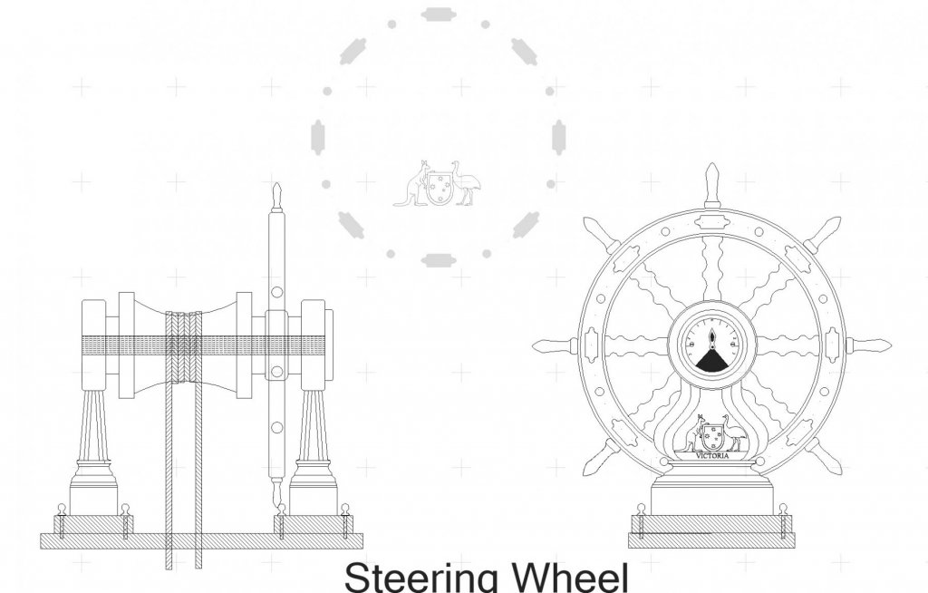
.thumb.jpg.e63aa403d8fd334a76e403d324dfd2b4.jpg)
- 1,013 replies
-
- 8
-
-
- gun dispatch vessel
- victoria
- (and 2 more)
-
Nice production run Dave; they look good. cheers Pat
- 742 replies
-
- 4
-
-
- constitution
- frigate
- (and 1 more)
-
HMCSS Victoria 1855 by BANYAN - 1:72
BANYAN replied to BANYAN's topic in - Build logs for subjects built 1851 - 1900
Thanks for the comments Eberhard, Carl and Steven, and for the likes folks - appreciated. Actually -- I had given some thought to the circular skylights Eberhard, and they have me cowering in the corner with the thought of attacking these. The current plan is to use an acrylic/perspex rod shaped on the lathe as the core then add a wood veneer to the side (with cutouts) and PE grills. Not sure yet whether to use a long strip for the side grills and put that on the inside of the veneer or attempt to put them on individually - at this scale that is a scary thought The upper conical grill will be drawn up and made as PE in a fan shape that will allow it to form the cone when rolled. In foreseeing the need, I recently made enquiries, including on MSW, for someone that does PE. As this will be a small job, I am not sure the costs would warrant third party development etc so I am looking at trying this myself sometime in the future (PE that is). Overnight I decided to have another go at the decals to see what I can get out of it. cheers Pat- 1,013 replies
-
- 5
-
-
- gun dispatch vessel
- victoria
- (and 2 more)
-
Glad to hear that you have resolved (within yourself) which way top step the masts Steven; that will allow you to move on with other work. The banking of the oars solution looks very workable with the mock-up looking very good - great idea. cheers Pat
-
HMCSS Victoria 1855 by BANYAN - 1:72
BANYAN replied to BANYAN's topic in - Build logs for subjects built 1851 - 1900
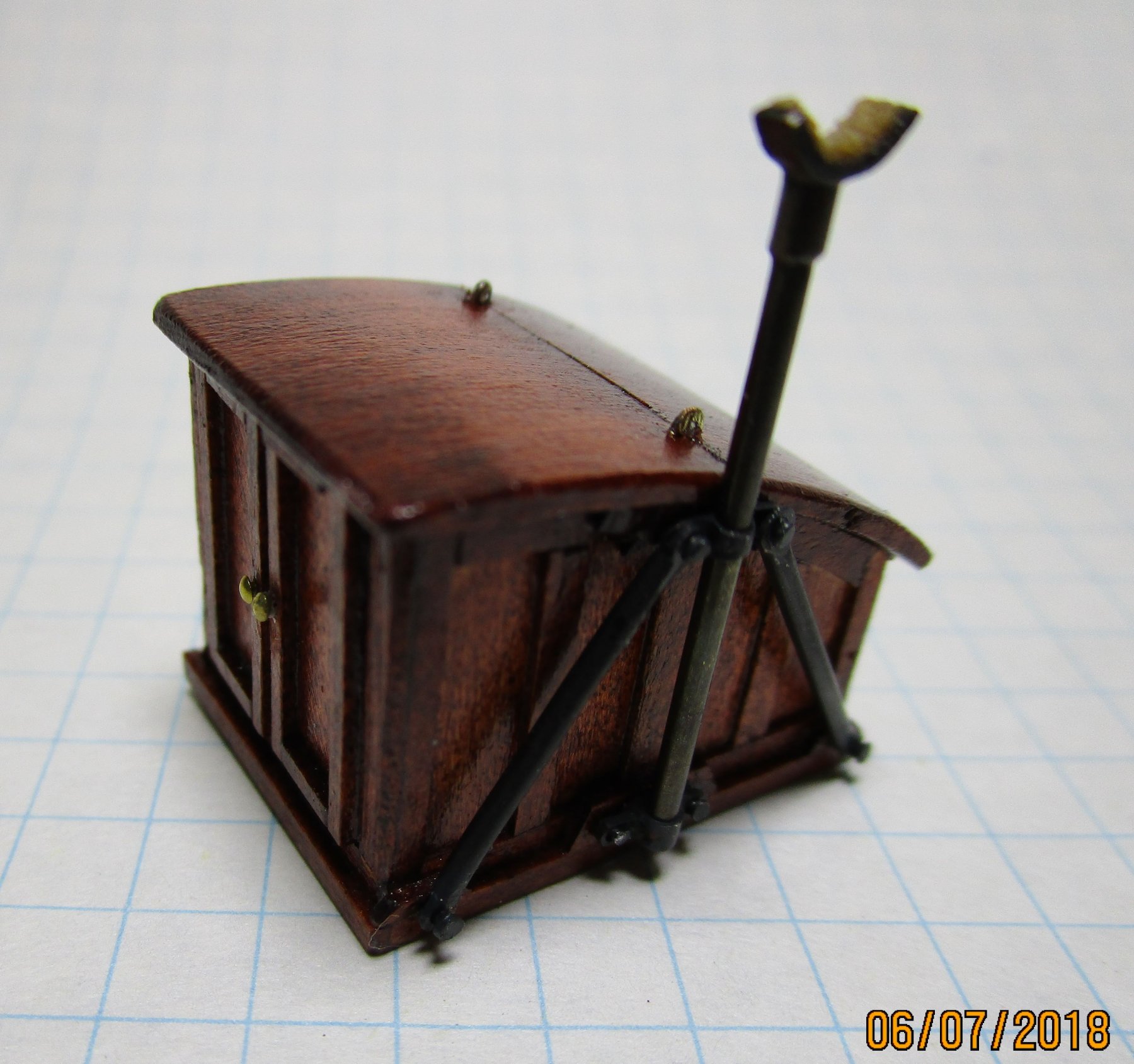
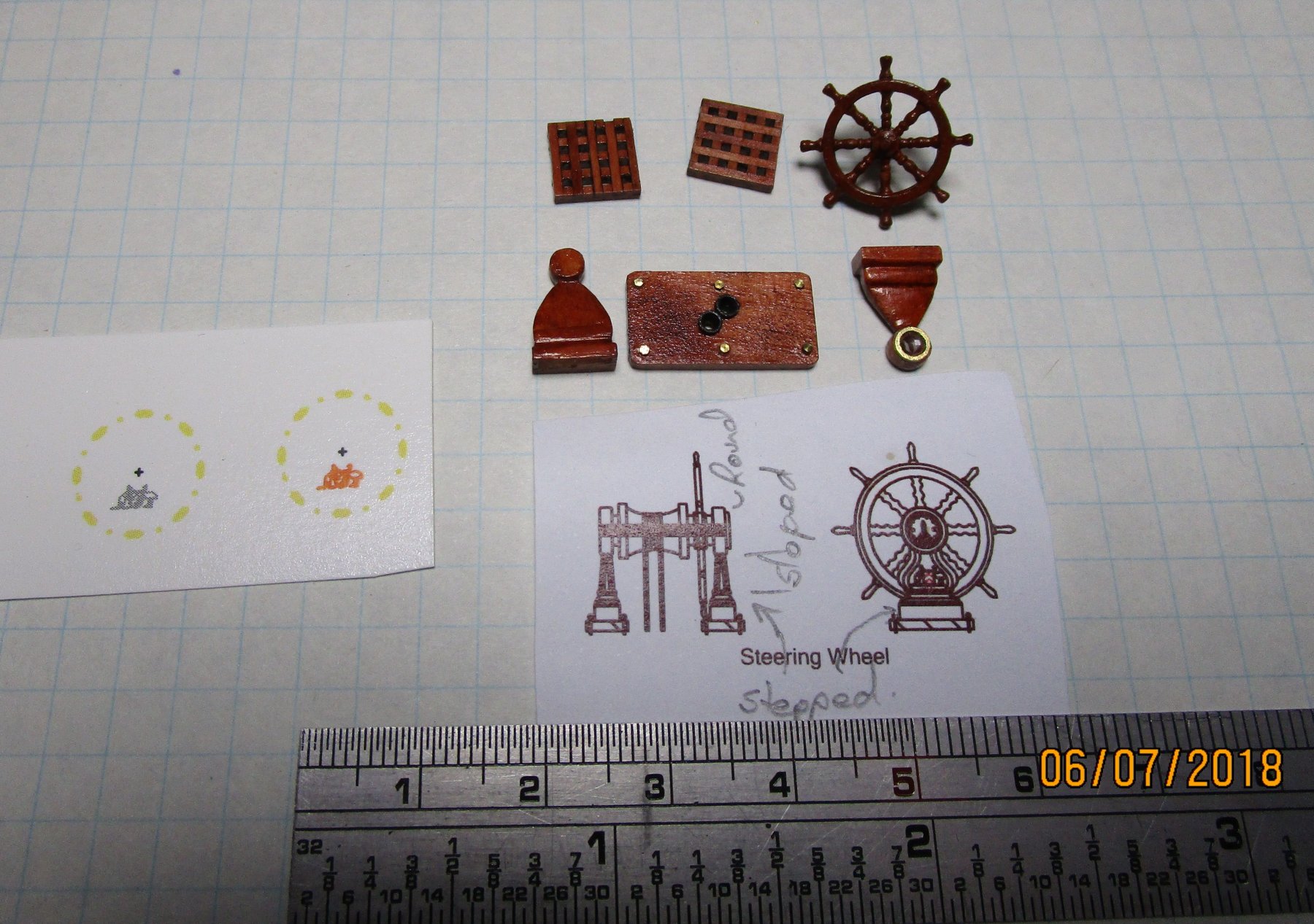
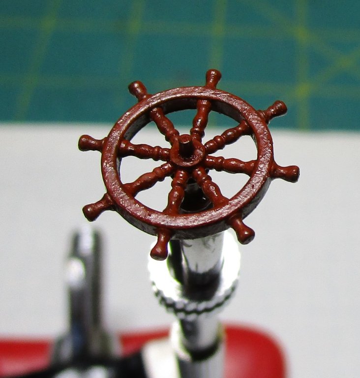
Another small update: I have progressed the wheel and standard a little further having painted the brass wheel. The paint to the eye looks smooth but it is very uneven when photographer so close up (noting the rim is only 1mm wide, and the wheel 14mm tip to tip). The paint is burnt sienna acrylic with a glaze made from varnish and wood stain. It looks pretty close to the wod used in the standard. One of the photos also shows all the parts ready to be assembled; including some decals I made. The decals were a dismal failure though as against the brown they just don't show up. I think I will have to paint the brass plates onto the rim of the wheel after all With my shaky hands they won't look too flash! Work in progress so to speak. I am not sure yet whether to try and further smooth the paint on the wheel; as i said - to the eye it looks OK. In the meantime the main companion has been completed; including the ironwork supporting the crutch for the main boom. I have included a close up extract from the quarterdeck photo as a comparison for what we have made. The legs supporting the crutch look a little oversize but these are less than 1mm diameter so near impossible for my fat hands to get smaller unfortunately - again the close-up photography makes it look rougher than it looks to the eye (the ironwork). cheers Pat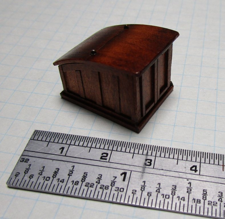


- 1,013 replies
-
- 19
-
-
- gun dispatch vessel
- victoria
- (and 2 more)
-
Nice work Danny, if one didn't know better you would never know this was card. cheers Pat
-
very neat solution Michael; well executed. cheers Pat
- 749 replies
-
- 5
-
-
- albertic
- ocean liner
- (and 2 more)
-
Nice work Rob, those spreaders look good! As Michael said; great to see you back at the modelling desk. cheers Pat
- 1,208 replies
-
- 3
-
-
- great republic
- clipper
- (and 1 more)
-
You've done a great job on those boats mate; they look really good. I am still debating about the locations/stowage of the boats but I have left them as is until I finally get about finishing the others. At this stage I think I will leave them as they are and place the other two on rods besides the ship to simulate them being in the water Cheating I know; but a lot easier. Your build is looking great; look forward to updates. cheers Pat
- 108 replies
-
- 1
-
-
- endeavour
- caldercraft
- (and 1 more)
-
Really nice work there Michael; lovely metalsmithing! cheers Pat
- 749 replies
-
- 7
-
-
- albertic
- ocean liner
- (and 2 more)
-
Hi Vinnie, I cannot be positive here as Bounty was smaller than Endeavour, but it looks like this is the lead block (288) for the Maintopmast preventer stay. The stay led through this block down to the deck as you have surmised. In Endeavour, this indeed di pass down through the lubbers hole to the port side and had a sister block turned into the tail end. The sister block is shaped a bit like a violin body with two single sheaves within one over the other with the larger sheave to the top. This allowed another single sheave block, rigged with a hook that was attached to an eyebolt in the deck to the port aft side of the foremast, to be rigged to form the main topmast preventer stay tackle which was used to tension the preventer stay. The Main stay was rigged in similar fashion with the lead block on the foremast under the top (at the start of the cheeks/hound) and led down to an eyebolt on the deck to the stbd aft side of the mast. The tail or running end of the tackle was usually secured back onto the tackle proper once tensioned. A similar arrangement existed for the mizzen stay and preventer stay with the blocks attached on the mainmast. Hope that helps a bit? cheers Pat
-
Nice details - love the oil stained decks, that is taking your weathering to extremes cheers Pat
- 405 replies
-
- 6
-
-
- tamiya
- king george v
- (and 2 more)
-
ancre Chebece 1750 by Jeronimo - FINISHED
BANYAN replied to Jeronimo's topic in - Build logs for subjects built 1501 - 1750
Beautiful work - a pleasure to view this build. cheers Pat -
My condolences to Pam and yourself. Best wishes for a full recovery; and yep, we all need time out - good luck in finding that 'stress-free' holiday site. regards Pat
-
HMCSS Victoria 1855 by BANYAN - 1:72
BANYAN replied to BANYAN's topic in - Build logs for subjects built 1851 - 1900
Thanks guys. I don't think I will resort to the paint brush at this scale Carl. The rim is only 1mm wide and 12mm in diameter; I think the chances of error due to shaky hands is too great. A challenge is one thing; ability is a whole different matter I think I have to agree Eberhard, decals sound the best way to go. Off to find some decal paper. Thanks for the feedback on the glazes; I was on the right track cheers Pat- 1,013 replies
-
- 5
-
-
- gun dispatch vessel
- victoria
- (and 2 more)

.jpg.2251f4eb52aaeb0be1a729ca30f02d82.jpg)