BANYAN
-
Posts
5,962 -
Joined
-
Last visited
Content Type
Profiles
Forums
Gallery
Events
Everything posted by BANYAN
-
 Some good progress OC; coming along very nicely. cheers Pat
- 455 replies
-
- 5
-

-
- slightly modified
- greyhound
- (and 1 more)
-
OK that's done it - I need a better (BIGGER) dictionary to find further superlatives - I have run out of ways to compliment your work ED That is craftsmanship at its highest standard. cheers Pat
- 3,618 replies
-
- 10
-
-
- young america
- clipper
- (and 1 more)
-
Very nice joinery; thanks for sharing your technique. cheers Pat
-
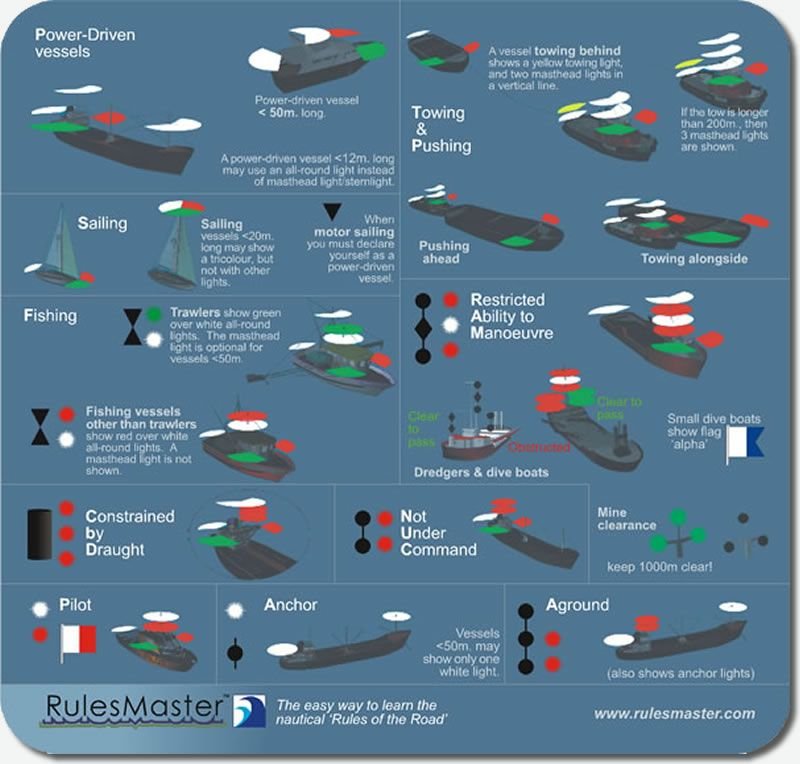
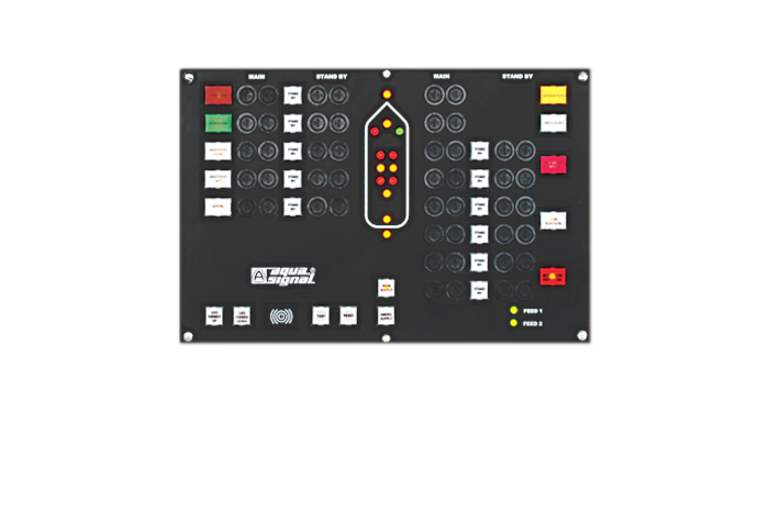
Great looking model Dan; the details are superb. If you look up "the task lighting" section of the "rules of the road" for maritime navigation you will find the appropriate task light colours. The main task lights will need to have catered for - not under command, restricted in ability to maneuver, and perhaps under tow, which mandate combinations of white, yellow and red lights in specific sequences, arcs of visibility and spacing. That may help determine the lighting colours and placement and add some interest? The attached pics provide a summary of some of the task and nav light Rules, and an example light control panel, that while a modern version covers the same types of light requirements for older vessels under the 'rules'. the insignia/logos on the images show from which companies/organisations the graphics originate. I hope this helps you add some life to the lights cheers Pat
- 287 replies
-
- 7
-
-
- michelangelo
- ocean liner
- (and 1 more)
-
HMCSS Victoria 1855 by BANYAN - 1:72
BANYAN replied to BANYAN's topic in - Build logs for subjects built 1851 - 1900
Thanks for looking in and kind comments Dave and John - welcome back to the fray to both of you Some further small updates coming very soon. cheers Pat- 1,019 replies
-
- 3
-
-
- gun dispatch vessel
- victoria
- (and 2 more)
-
Looking good Mark; nice to have a laser cutter for accurately fitting parts. cheers Pat
-
Great progress and looking great Patrick. Is it just the angle of the camera or does the flare of the hull (stbd side) at about the two-thirds back mark seem a little wider than for the port side? cheers Pat
-
Looks great Dave; welcome back I hope you had stern words with those slackers in the dockyard cheers Pat
-
Hi Rod, see my response to your PM for some answers, however, a couple of clarifying points for you to ponder. A ship is steered by a helmsman using a compass and is 'conned' on to the course to be steered by the deck officer (Officer of the Watch in RN terms) or the Captain (whomever has the control of the ship). I think it was this way even back then also. The helmsman does not need to see ahead but does need to see the sails (to keep them filled) and have a clear view of the compass - seeing ahead is a bonus So a large binnacle would be okay. The style, design or size of the one used in Endeavour will probably never be known. I went with the larger one (Marquardt) as this being a ship of exploration and, when being refitted, potentially for survey as well, I believe the availability of two compasses a necessity. That does not mean your interpretation is incorrect and may well have been one a possible fit. I only raise my point for consideration. cheers Pat
- 108 replies
-
- 3
-
-
- endeavour
- caldercraft
- (and 1 more)
-
You always achieve such clean crisp joints Chuck; very impressive. Love the wood tones! cheers Pat
- 1,784 replies
-
- 5
-
-
- winchelsea
- Syren Ship Model Company
- (and 1 more)
-
Another warm welcome from downunder Greg; interesting genealogy and one you can be justifiably proud of. cheers Pat
-
Nice work with the case Mike; especially in your recovery of the break. cheers Pat
- 969 replies
-
- 4
-
-
- hahn
- oliver cromwell
- (and 1 more)
-
Hi Rod, you are making good progress with your build of Endeavour; I'll pull up a seat and follow-along also. As you noted the anchor linings are not well covered in most kits. For mine I dry fitted the anchor to the cathead then traced the arcs the anchor flukes followed as they were catted or lowered in preparation for dropping. that gave me the 'real' arc the lining had to follow. The deck fittings were the most enjoyable for me and you have several good options in the various plans, books and replicas to follow as to how they looked. cheers Pat
- 108 replies
-
- 1
-
-
- endeavour
- caldercraft
- (and 1 more)
-
HMCSS Victoria 1855 by BANYAN - 1:72
BANYAN replied to BANYAN's topic in - Build logs for subjects built 1851 - 1900
Many thanks Druxey and Denis; appreciate you both looking in and for the kind words. cheers Pat- 1,019 replies
-
- 2
-
-
- gun dispatch vessel
- victoria
- (and 2 more)
-
Wonderful looking model John; I really like the detailed carvings and extra bits and pieces which make it look very authentic. Better keep your 'helper" away from it cheers Pat
-
Great to have another update of this very fine model Alex. i love the contrasting wood between the deck planks, margins/waterway and bulwarks. cheers Pat
-
Nice to see an update Tecko and what a great tribute to your mate; I am sure he appreciates it. I don't know why you were concerned with modelling the bike; it has turned out terrific. cheers Pat
-
HMCSS Victoria 1855 by BANYAN - 1:72
BANYAN replied to BANYAN's topic in - Build logs for subjects built 1851 - 1900
Thanks for the very kind words and encouragement Russ, Ed, Jason, Carl and Eberhard. Compliments from you guys, noting the exquisite work you do, is very much appreciated. regards Pat- 1,019 replies
-
- 2
-
-
- gun dispatch vessel
- victoria
- (and 2 more)
-
Just found your build log and to say I am impressed is a very large understatement - superb modelling skills! I will be following with interest. cheers Pat
-
HMCSS Victoria 1855 by BANYAN - 1:72
BANYAN replied to BANYAN's topic in - Build logs for subjects built 1851 - 1900
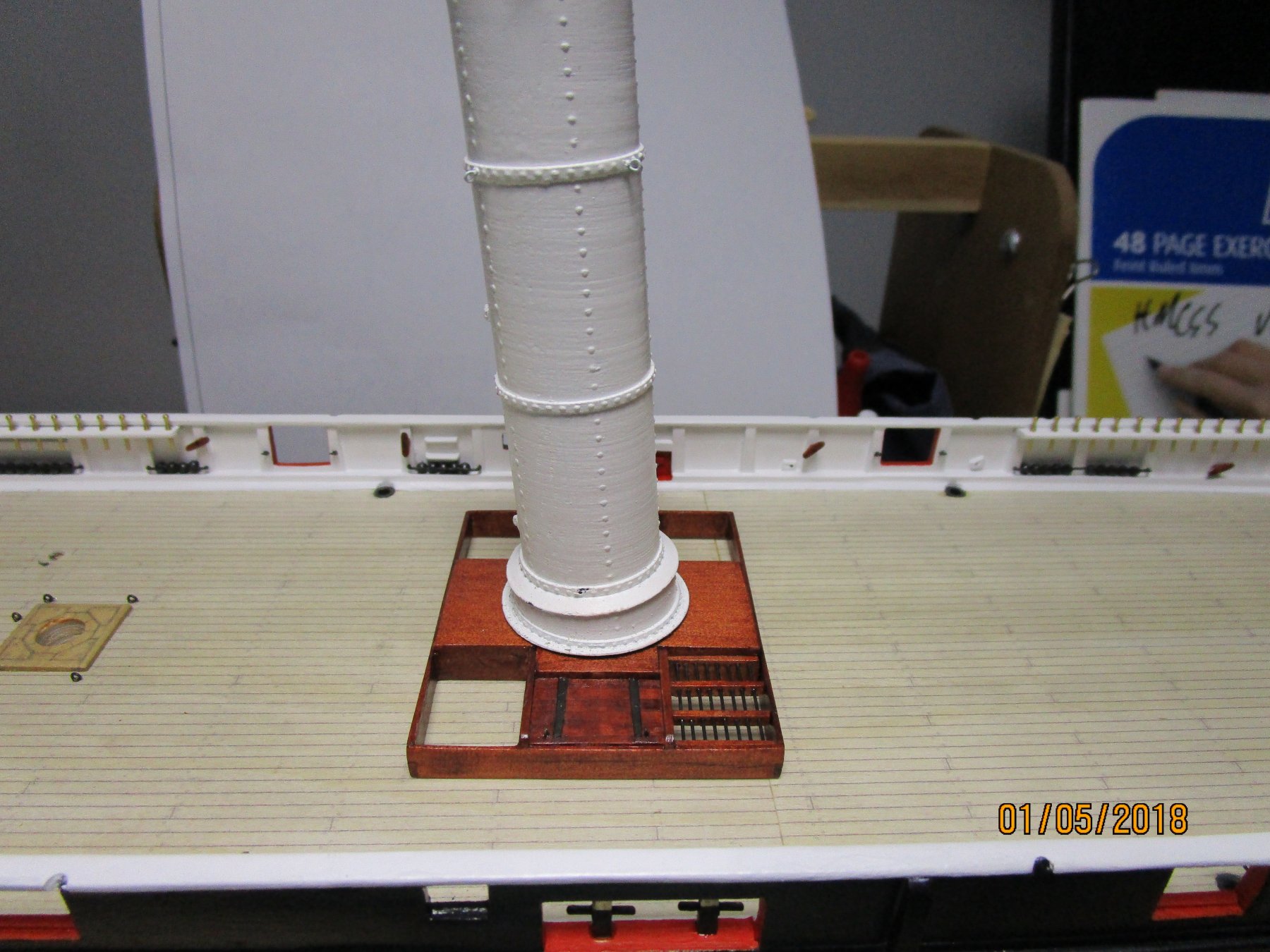
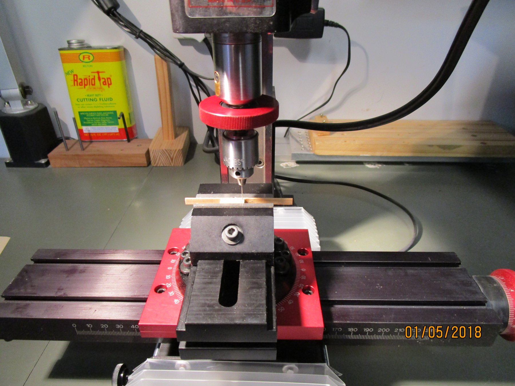
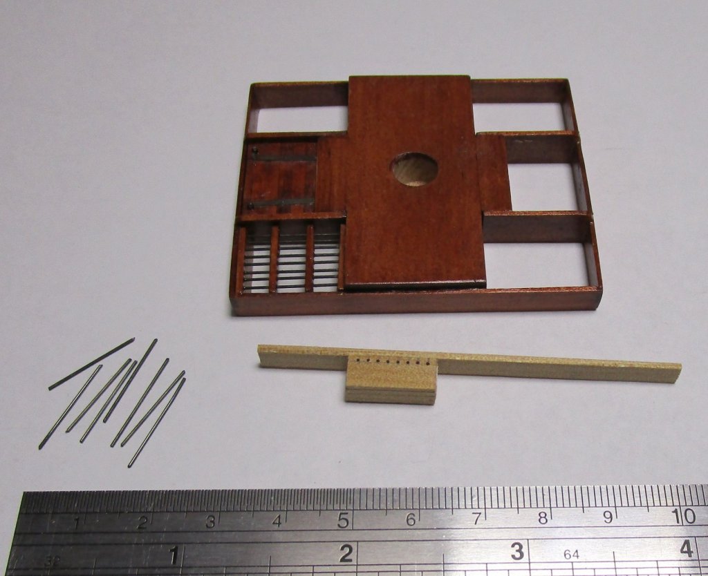
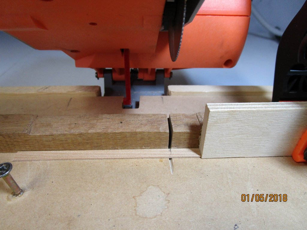
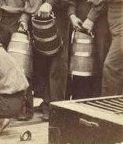
I have also started on the boiler space skylight and funnel platform. The photo shows progress to date with one hatch and one grating placed, and the funnel dry fitted in-situ. I have also attached two photos showing some of the detail for making the gratings (one on each corner) which are open to the weather to ensure adequate air for the boilers to draw. When shut down, a tarp was drawn over the top. The other photo shows the corner of the skylight taken from one of very few photos of the ship which confirms the grate is open; the metal batten pins can just be made out - I will add these later. To make the grate, I first cut 4 lengths (sized to fit the opening) with my chop saw, I then stack these with a bit of double sided tape between layers then drill the holes with mill using a sensitive drill attachment. I then stain and varnish the wood, thread the blackened brass rod (0.5mm) and use a touch of CA to hold the rod ends in place - the whole assembly is press fitted into the opening. cheers Pat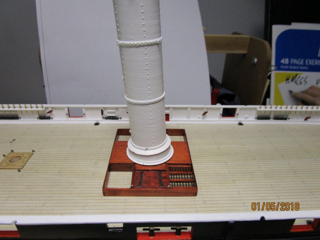

- 1,019 replies
-
- 12
-
-
- gun dispatch vessel
- victoria
- (and 2 more)