
HOLIDAY DONATION DRIVE - SUPPORT MSW - DO YOUR PART TO KEEP THIS GREAT FORUM GOING! (Only 24 donations so far out of 49,000 members - C'mon guys!)
×


BANYAN
-
Posts
5,936 -
Joined
-
Last visited
Content Type
Profiles
Forums
Gallery
Events
Everything posted by BANYAN
-
 Hey Greg, any chance of slowing down - I am getting dizzy trying to keep up with your builds This looks like a great project and you are certainly off to a really good start. Your research in your quest for accuracy will result in a great model of her. No room in the rafters so i'll take a pew in the foyer (better access to the popcorn out there :)) cheers Pat
- 405 replies
-
- 8
-

-
- tamiya
- king george v
- (and 2 more)
-
Hi Bob, that 'speed knob' sounds very interesting - I have a Zyliss and find the crank handle cumbersome also. Any chance of posting a picture and if you could please advise the materials you used? I think I understand the concept of your adaption/device but a pic to confirm would be much appreciated. For all - i am also looking at some way to convert a inset tail vise (set into and flush with the top of the bench) so that I can adjust it from the top as I cannot access the end of my bench. I wish to use it in conjunction with some bench pups/dogs but all the tail vises I have found all require you to crank the handle from the end of the bench rather from the top using a crank handle inserted into a receiver much like the lifting mechanism for a router. Any suggestions most welcomed cheers Pat
-
Ah, my day is complete (well almost) - have been missing your updates Ed. She is really taking shape now and as always your finishes and build quality are of the highest quality. cheers Pat
- 3,618 replies
-
- 8
-
-
- young america
- clipper
- (and 1 more)
-
Your research effort and commitment to authenticity is commendable Steven. The model detail is looking good! cheers Pat
-
Great progress and glad to hear you are having a lot of fun with the build. looks great! cheers Pat
- 108 replies
-
- 1
-
-
- endeavour
- caldercraft
- (and 1 more)
-
Endeavour anchors
BANYAN replied to Caz's topic in Discussion for a Ship's Deck Furniture, Guns, boats and other Fittings
No problem Casper; glad the book helped. The bowers were definitely in the 'bows'; some ships had two different sizes with the larger or 'best' bower to the stbd side I think. In Endeavour though, I think they were both the same size. cheers Pat -
Laying out plans in a smaller workshop
BANYAN replied to alde's topic in Modeling tools and Workshop Equipment
I use a metal wall strip purchased from my local office wares supplier (OfficeWorks here in Australia) that has a mechanism that allows several sheets/plans etc to be held. It is only about an inch (25mm) in height and only protrudes out about 10mm out from the wall - it attaches to the wall with screws or 2-sided tape. Works a treat for me with minimal impact on roomspace etc. but still handy to view. Only problem I have experienced is that sometimes when removing one sheet, others may come out with it also; but, they are very easy to put back into the holder - just slide the top edge of the sheet/plan/ picture up and it grips, swing the sheet/plan out to about 75 degrees from the wall and it comes out easily. You can make it out hanging on the wall to the left in the photo. Cannot recall what it is actually called - sorry. May come up under paper display strip or the like? cheers Pat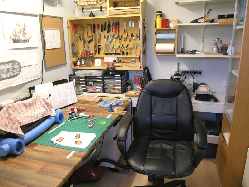
-
Endeavour anchors
BANYAN replied to Caz's topic in Discussion for a Ship's Deck Furniture, Guns, boats and other Fittings
Hi Caz, drawings/sketches of their locations may exist but I have not seen them; someone like Shipaholic may be able to better inform you with the research he has done. That sid, I believe the general practice, of the time, was to stow (lash down) the 'stream' anchor on the starboard main channel and the kedge on the port mizzen channel. I cannot provide a reference at this stage but have read it somewhere and I stand ready to be corrected cheers Pat -
Incredible Genealogy Find (R.M.S. Baltic Stationary)
BANYAN replied to Mike Shea's topic in Nautical/Naval History
A great find for you and a very interesting maritime connection for your family. cheers Pat- 3 replies
-
- 4
-
-
- titanic
- historical
- (and 1 more)
-
HMCSS Victoria 1855 by BANYAN - 1:72
BANYAN replied to BANYAN's topic in - Build logs for subjects built 1851 - 1900
Thanks Dave; practice makes perfect they say so I'll have to do about another 6 or so yet cheers Pat- 1,006 replies
-
- 5
-
-
- gun dispatch vessel
- victoria
- (and 2 more)
-
I would not know for sure Steven, but your logic is sound for placement in the bulge at the top. cheers Pat
-
Slowly getting there Dave; she is looking great with her added finery (rigging) cheers Pat
-
A very methodical and practical approach that will serve you well Jason; looks very good. cheers Pat
-
I have difficulty with dovetail joints in full sized carpentry yet alone at this scale - BRILLIANT! cheers Pat
-
You set a very high standard to follow Ed; another example of very high quality work. cheers Pat
- 3,618 replies
-
- 5
-
-
- young america
- clipper
- (and 1 more)
-
Precision joinery and very high quality finishing Amalio; a joy to view and follow. cheers Pat
-
Nice work Carl, she is coming along very nicely. cheers Pat
- 1,090 replies
-
- 8
-
-
- showcase models
- vendetta
- (and 2 more)
-
Hi Matrim, just found your log. Great progress and don't be too disheartened with the extreme close-ups as not too many modellers pass examination at that range WRT the carriages, don't be so hard on yourself as kit manufacturers are well known for using the same parts across several models (even at different scales) as a cost saving measure. cheers Pat
- 38 replies
-
- 2
-
-
- bounty
- caldercraft
- (and 1 more)
-
Interesting discussion folks. I am currently researching, drawing up and building a 1:72 model of HMCSS Victoria - built 1855 at Limehouse Docks in London - she was based on contemporary RN Gun Despatch vessel lines but modified for a more sleeker (longer and less-wide) by her designer Oliver Lang. Her masts were extremely raked with the Fore - 5 degrees aft, Main -10 degrees aft and Mizzen - 15 degrees aft - and yes I have 'triple' checked these even superimposing a photograph of her over the profile plan. She was also known as a fast ship easily attaining 13+ knots at sea (in the right conditions) and having achieved 14.5 knots over the measured mile during her sea trials (under sail alone). She was a Barque rigged vessel to Royals only and standard topsails - not the 'split' (upper and lower topsails) used in the clippers etc. Just for interest. cheers Pat
-
Slow but steady progress will get your there Patrick; she is looking really good already. cheers Pat
-
Thanks Mark. cheers Pat
-
Glad to hear you have a solution Bill, good luck with the build. Thanks Mark, I was unsure of who/where I got it - now that you mention Jerry, I agree it was his build of Constellation. So0rrt Jerry, and I hope you don't mind us re-sharing it? That is a nice model Mark, i hadn't seen this build of yours before. Bill, if you will permit me hijacking your thread, I would like to try and get some clarifications on the 'fold down' bulwark panels. I had considered these but could not find any definitive info that these were used and would appreciate any info on the hinginging and support mechanisms. My initial thoughts were that these panels were very heavy being thick (outer and inner planked large sections) that would have placed a lot of strain on the hinging and there appear to be no topping lift type (hanging) supports in the form of wire guys etc also. Must have been hell raising them again. That said, if used there must have been some info / data available about these? I am seeking this info to offer in my 'considerations' for the selection of various fittings, equipment and build methods in an associated build log text I am putting together. At this point I am assuming this was a US build practice? I haven't seen evidence of it used elsewhere (well in my limited searches to date) cheers Pat
-
Great build Greg, a very nice addition to your collection. Any plans on a HMAS Sydney? cheers Pat
- 1,090 replies
-
- 7
-
-
- showcase models
- vendetta
- (and 2 more)