
HOLIDAY DONATION DRIVE - SUPPORT MSW - DO YOUR PART TO KEEP THIS GREAT FORUM GOING! (Only 13 donations so far - C'mon guys!)
×


BANYAN
-
Posts
5,929 -
Joined
-
Last visited
Content Type
Profiles
Forums
Gallery
Events
Everything posted by BANYAN
-
 HI Patrick and thanks for the update; I was wondering what had become of this build. You have become a real master of these little beauties, especially the amount of detail you include. cheers Pat
 -
Sometimes the simplest of jigs provide the best solution. Very creative and the excellent result speaks for itself. cheers Pat
-
Welcome back, and happy NY Jason. glad to hear the damage was not too bad, but must have been a bit of a 'scare'. Very nice clean work (up to your usual high standard) on the planking. cheers Pat
-
Another masterclass in metal working, thanks Keith. This model will be one that stands u to even the most 'macro' of examinations without fault. Happy New Year. cheers Pat
-
Welcome back Dave; great to see the update which is up to your usual high quality and finish. cheers Pat
-
A great comparison Rob; clearly shows the different requirements met by the respective designers. Very nice models too! Odd sea pattern under them though - fan blade shaped waves Welcome back to the builders desk - I am still a week or two away while I finish all those house jobs. cheers Pat
-
Nice work Steven, a very interesting and well executed build. I have enjoyed the journey. cheers Pat p.s. As much as I tried, I could not see Ron's telepromter!
-
An interesting subject for your SIB Glen, and a very unique display base in the form of the sledge (very nicely executed BTW). I look forward to seeing your build at such a small scale. cheers Pat
-
Sorry I don't have the expertise to participate but would be an interested 'looker on' Good luck with this endeavour; has the m akings for an excellent book! (hint) - it doesn't have to be commercial endeavour. cheers Pat
- 3,560 replies
-
- 1
-

-
- clipper
- hull model
- (and 2 more)
-
NAIAD 1797 by Bitao - 1:60
BANYAN replied to Bitao's topic in - Build logs for subjects built 1751 - 1800
Wow, wow and more wow! cheers Pat -
That's an interesting result; I have not had the need to use Steel for my calculations. Thanks for the head's-up on this. I think you are quite safe in your build decisions unless you run into a 'rivet counter' cheers Pat
-
Very nice work on the rudder heads, races, funnels and steering wheel - some very well detailed fine work Brian - take a bow! Those desk tidies certainly help in organising the workspace. cheers Pat
-
The skylight came up nicely Eberhard. I had to make similar sized but had mine fully etched in 0.1 mm brass which turned out OK; I am assuming you tried that without success? Wishing you all the best wishes for 2022 cheers Pat
-
Back at you all - I hope all have a safe and very happy Christmas. cheers Pat
- 3,560 replies
-
- 2
-
-
- clipper
- hull model
- (and 2 more)
-
Excellent paint job; love it! Nice addition to your collection Greg, adds perspective to the size of these air ships. Have a safe and happy festive season Pat
-
NAIAD 1797 by Bitao - 1:60
BANYAN replied to Bitao's topic in - Build logs for subjects built 1751 - 1800
A very Merry Christmas, and best wishes for a safe and happy festive season to you and your family also Bitao. Love watching your work. cheers Pat -
Nicely done Greg. Seasons greetings - have a safe and happy festive season Pat
- 1,090 replies
-
- 4
-

-
-
- showcase models
- vendetta
- (and 2 more)
-
Is there any 'manufacturing' problem that has ever stumped you Keith? Ditto above comments - your ingenuity (and quality of work) never fails to amaze! cheers Pat
-
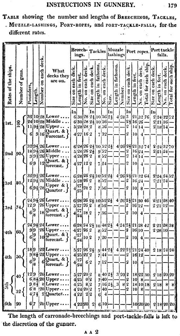
Dave, Allan et al - not sure if you are aware of the 'The Sea Gunners Vade Mecum' by Robert Simmons (1812)? The following is from that reference and I think it is a downloadable pdf (digitised by Google). cheers Pat
-
This is going to one very fine model Rob. cheers Pat
- 3,560 replies
-
- 2
-
-
- clipper
- hull model
- (and 2 more)