


BANYAN
-
Posts
5,965 -
Joined
-
Last visited
Content Type
Profiles
Forums
Gallery
Events
Everything posted by BANYAN
-
 Excellent paint job; love it! Nice addition to your collection Greg, adds perspective to the size of these air ships. Have a safe and happy festive season Pat
 -
NAIAD 1797 by Bitao - 1:60
BANYAN replied to Bitao's topic in - Build logs for subjects built 1751 - 1800
A very Merry Christmas, and best wishes for a safe and happy festive season to you and your family also Bitao. Love watching your work. cheers Pat -
Nicely done Greg. Seasons greetings - have a safe and happy festive season Pat
- 1,090 replies
-
- 4
-

-

-
- showcase models
- vendetta
- (and 2 more)
-
Is there any 'manufacturing' problem that has ever stumped you Keith? Ditto above comments - your ingenuity (and quality of work) never fails to amaze! cheers Pat
-
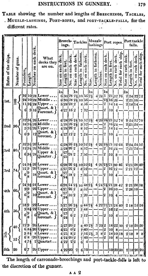
Dave, Allan et al - not sure if you are aware of the 'The Sea Gunners Vade Mecum' by Robert Simmons (1812)? The following is from that reference and I think it is a downloadable pdf (digitised by Google). cheers Pat
-
This is going to one very fine model Rob. cheers Pat
- 3,560 replies
-
- 2
-
-
- clipper
- hull model
- (and 2 more)
-
Hi Keith, yep. Basically it is a large clamp to hold several rows of pre-cut (sized appropriately) strip stock with sacrificial pieces on each end/side. Once set-up you can make several hundred at a go depending on how much drilling and milling you wish to do. cheers Pat
-
Good idea Keith (Aug), can I extend an invitation for you to check my tutorial using your skills ? I only have a few hundred to do Good luck Keith (Black), they are fiddly things - I am in the process of developing a jig to mass produce them based on a system used by some Russian modellers that was posted in MSW Gen 1. cheers Pat
-
Agreed re franchises, but they are now talking of further diversifying into larger shops selling electronics and electrical gear also. Please AP, just concentrate on getting deliveries right at a reasonable cost! Sorry to hijack your build, and I'll get off the soap box now cheers Pat
- 1,090 replies
-
- 4
-

-
-
- showcase models
- vendetta
- (and 2 more)
-
Greg, HMAS Castlemaine (Bathurst Class) is just down the road from me if you need any visual 'clues' Aussie Post need to start concentrating on improving their core services (delivery times) instead of trying to further diversify - they simply cannot blame covid restrictions any more. cheers Pat
- 1,090 replies
-
- 4
-
-
- showcase models
- vendetta
- (and 2 more)
-
The tops look great Rob, suits the overall mast colour scheme. cheers Pat
- 3,560 replies
-
- 1
-
-
- clipper
- hull model
- (and 2 more)
-
Deviate away my friend; I am sure the majority of us find it as fascinating as your excellent building skills. cheers Pat
-
Rob, I am still bobbing along in the wake of your journey of discovery - very interesting following along. cheers Pat
- 3,560 replies
-
- 1
-
-
- clipper
- hull model
- (and 2 more)
-
You have done a great job on this model mate; the details are outstanding. Love the way the covers for the boats worked out; I'll tuck that idea away for future use. cheers Pat
-
Hi Mark, thanks for the response. I am more and more convinced it is something in the system/network and not staffing etc as it does not matter whom I tried - the same result. I had cut back even leaving several days between posts. Sponsor or not, having spent thousands of dollars with them, I cannot fathom the short/rude responses. Hi Tom, it doesn't matter whom (Kat, Kim...) if it has the sherline.com email domain I have the problems. Hi Grant, thanks for the suggestion, I think I will try that - much appreciated. cheers Pat
-
Not sure if this is the right forum - moderators please move if not. Has anyone else had bad/poor experiences communicating with Sherline Support via email in recent times? I have checked all communications aspects my end but only the very occasional email (from my end) gets through; and they refuse to accept it may be their system, or more likely their ISP, causing the issue. They just do not seem to have any interest in resolving the issue . To me this seems a very unprofessional approach by them in trying to resolve the issue. Sherline Support is the only site I have experienced/am experiencing email difficulties with, I have checked with my ISP and all is fine with my email client, account settings etc etc). As stated above, the occasional email gets through to them (1 in say 20) but they then accuse me of not responding to their emails rather than trying to establish the root cause of the issues. If I place, amend or cancel an order through their 'ordering system' all is good, but trying to get through/communicate with support staff is nigh impossible. It is my educated 'guess' that their ISP has an over sensitive analysis algorithm/count on emails sent by someone and puts you in their 'spammers' list far to readily. I had this experience in reverse a few years ago, and I had to contact my ISP to resolve it. In this current case I was sending several emails a day to Sherline organising the bits I wanted and payment, then suddenly all went haywire - this does not seem to be an issues with any other retailer/supplier I am in contact with (especially in the US). I raise the issue to try and resolve what the cause is, not to 'bag' them! However, they simply do not seem interested in resolving the issue at all unfortunately, so if I want bits and bobs/accessories I need to prove my case; and hopefully they may listen (if I can get through to them again that is ). cheers Pat
-
Hi again Richard, the other trick I have tried was to print a 'skin type' light pattern (which included the nail/tacks on the edges) onto brown paper, and pasted in place with a matt varnish. if the leather idea doesn't work out, this may also be worth experimenting with. cheers Pat
-
Nice find Bruce; thanks for sharing. If anyone is interested in this ship, Bob Sexton (who is associated with the SA Museum) has done some research and drawn some plans for this vessel. cheers Pat Edit: SA = South Australia
-
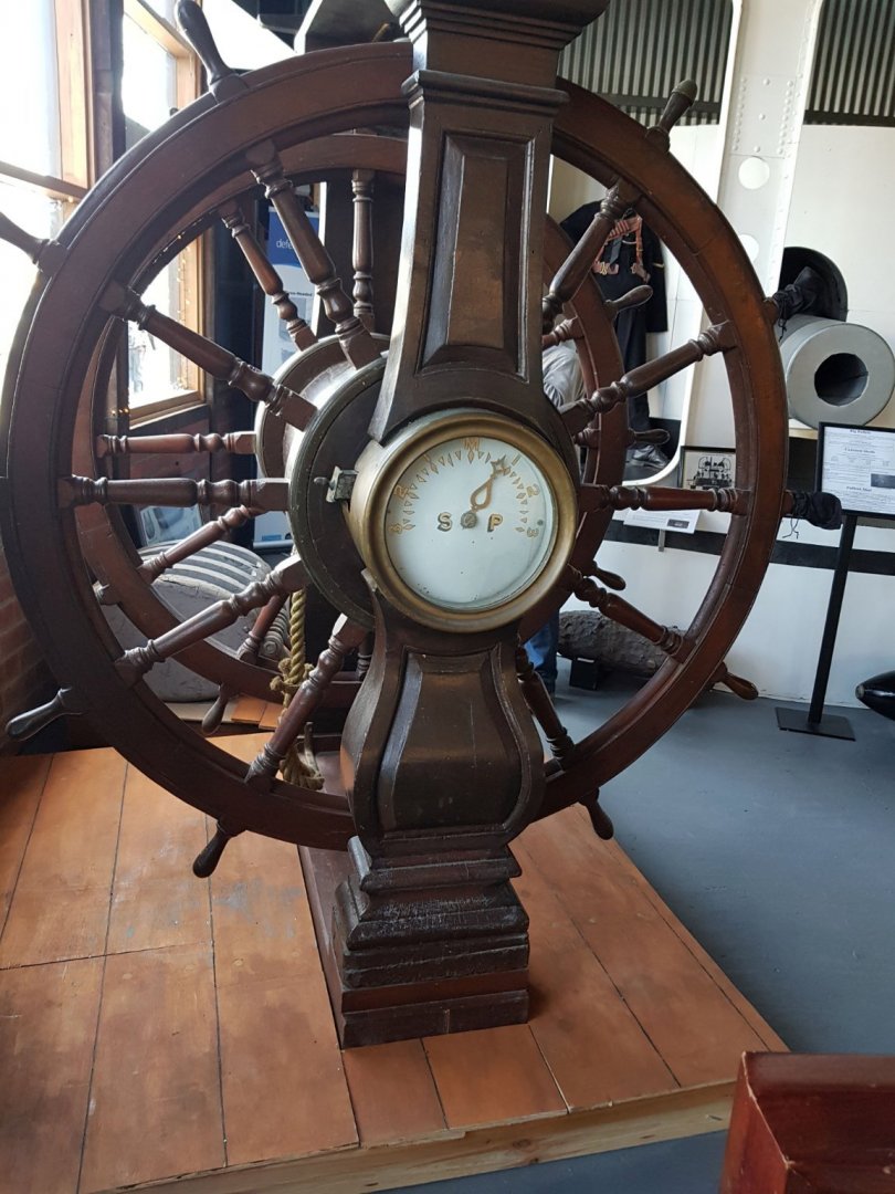
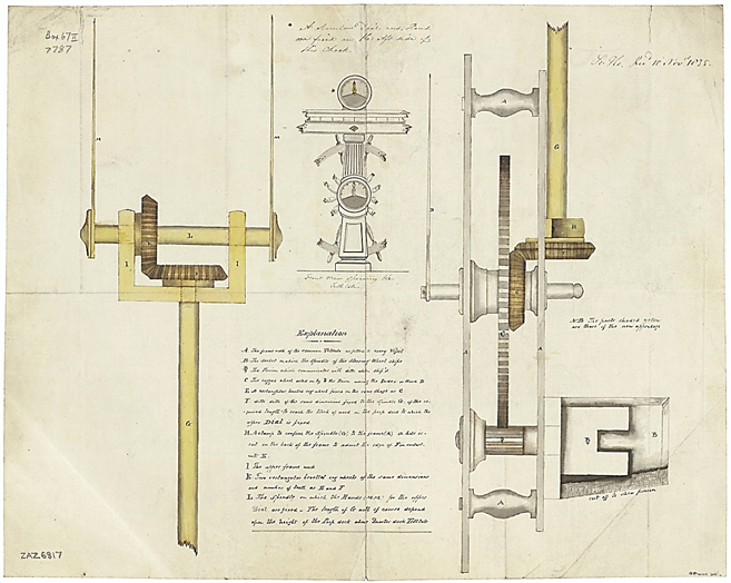
Hi Eberhard, perhaps the item was an 'axiometer',(tell-tale), which had been introduced into RN service by 1835; for the rudder or wheel. Some ships had a double, some a single - the attached is a double (one for wheel, one for rudder) but I cut it off Your example may have stood independently. The picture below is the wheel from HMS Nelson (1814). I have also attached an example of its mechanism (NMM Collections – ZAZ6817). cheers Pat
-
Very nice work Eberhard, certainly looks like wood. "Victoria' used rope also but made from 'green hide' kept well oiled. I think your assumptions are spot on , especially for ships still using wood wheels (rather than iron etc). cheers Pat
-
Very nice work Steven; the use of your very nicely carved crew really puts a lot of 'perspective' (and colour) into your builds. cheers Pat

