-
Posts
3,173 -
Joined
-
Last visited
Content Type
Profiles
Forums
Gallery
Events
Everything posted by Gregory
-
The 1/8 shank ones are carbide. The carbide ones break very easily, but work well if one is careful.
-
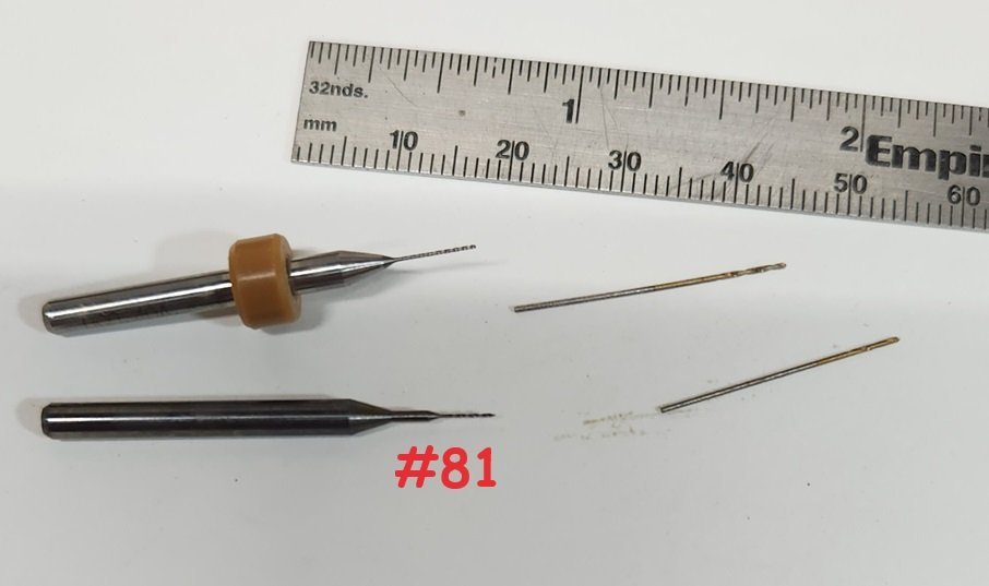
I don't anticipate doing any work that can't be done with the 1/8 shank micro drills, and I have them at least as small as #81.
-
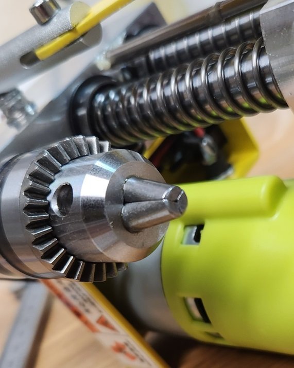
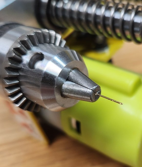
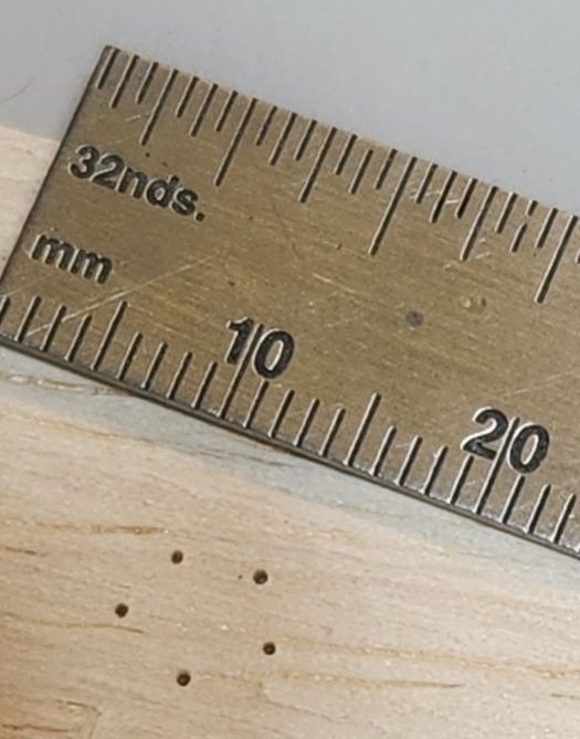
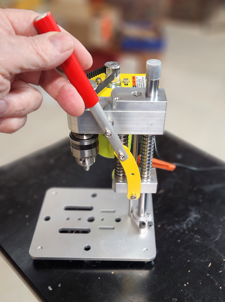
I have found the listed specs for all kinds of Chinese stuff to be unreliable. Generally, they are not catering to a market that cares about that kind of accuracy. Here is a close up of my chuck. I think the appearance of that opening is deceptive. It's certainly smaller than 1/32. Here are the smallest bits I have. Of course, the 2 with the 1/8 shank are not an issue. I don't have any decent calipers right now, but the bit on the bottom right is a little smaller than 24 gauge wire. ( .028" ) Here it is chucked up. Here are a few holes in some plywood with the bit above. The piece wasn't clamped , so there may have been some micro-movement. I'm looking froward to using this on a project.
-
I share your concern, however as I noted the power draw at 24V is only 17W at 24 volts, so for short term I think it will be OK. I'm more inclined to get a more robust DC supply and use something like this: DC to DC Step Down Power Supply
-
It just occurred to me that a picture with my hand in it would give a much better perspective of size. Now you know why I never made it as a " Hand Model " ..
-
Tiny "precision" drill press
Gregory replied to Ron Burns's topic in Modeling tools and Workshop Equipment
I just posted my first impressions of the machine I mentioned above. Mini Bench Drill Press I haven't had time to do any real work with it.. I will try to follow up soon. -
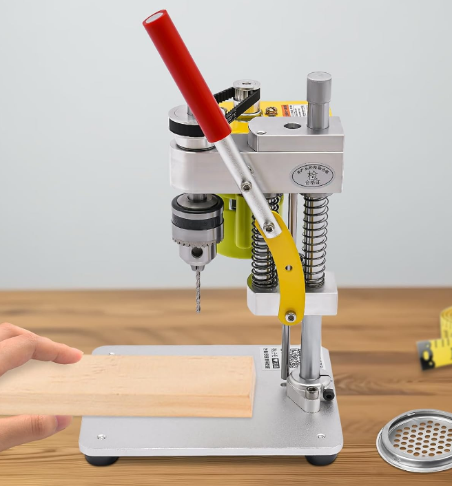
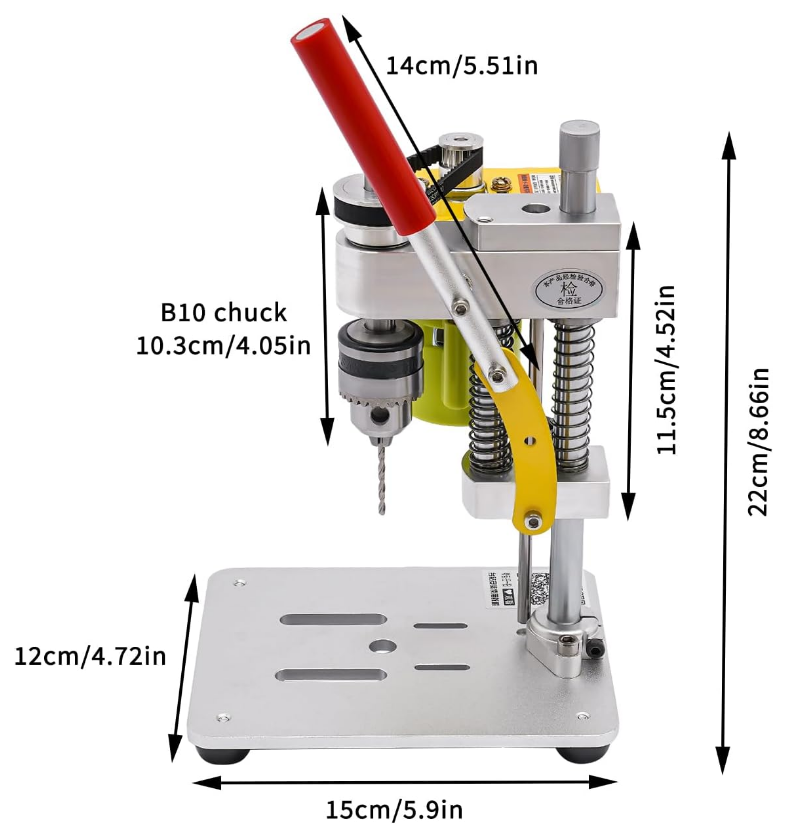
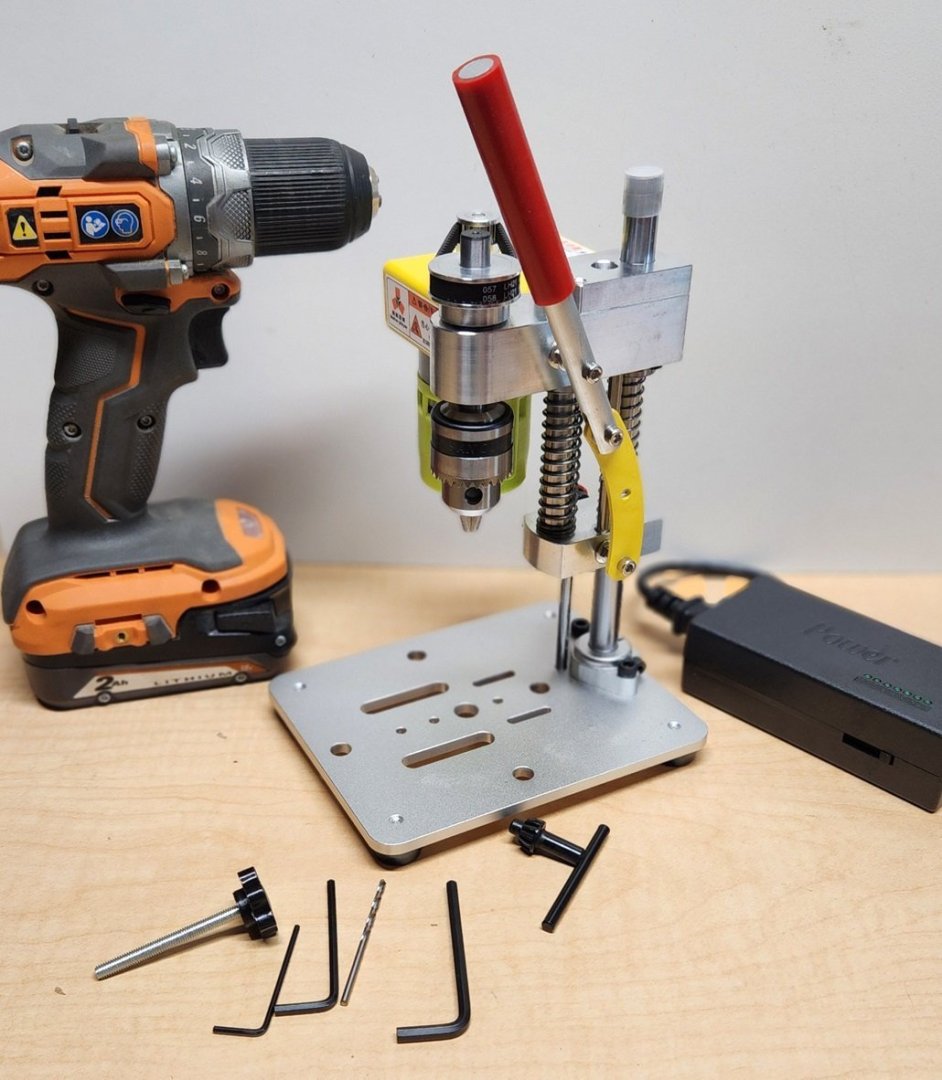
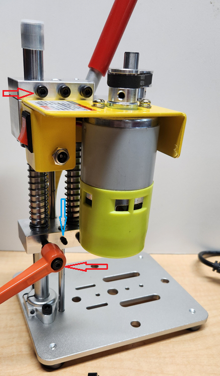
Ron Burns Topic about a mini drill press got me interested in looking for something to replace my Dremel version which leaves a lot to be desired. I went ahead with this one from Amazon which gives me the option of returning it hassle free. It's listing now for $69.99. There are several different vendors selling what appears to be identical machines, at different prices, with various accessory packages and minor construction differences. Here is an illustration showing the dimensions. The head vertical travel is about 1 & 3/4 inches, which is plenty for my purposes. The head can be swung from side to side using some lock down screws, which I will discuss further later on. I think the size is going to be great for the modeling environment. A much smaller footprint than my old Dremel set-up. Here is mine with everything that was in the box. I put the 3/8 inch drill there to give a little perspective to the size. It weighs in at 3.6 LB. (The product listing says 4.8 LB, but maybe that was with everything in the box plus the box ) Materials and workmanship appear 1st rate. Shafts and head parts appear to be stainless steel, but the listing says something about the shafts being chrome plated something. I guess the head parts could be aluminum, but it feels heavier than what I would expect for aluminum. Base is aluminum with a very smooth finish. No rough edges or burrs on any of the parts. No detectable play where it matters, so securing the work piece seems to be the main concern here. I'm exploring some vise options. The main challenge will be getting a decent vise that will work in the available space. The ones I am looking at will cost as much or more than the drill press itself. The red arrows point to the swivel lock screws. The bottom one has a lever that is not shown in the Amazon illustrations. It makes for easier adjustments, however the upper screw requires an allen wrench, which I feel is somewhat inconvenient. They do provide a long screw with a knob on the end that I think may replace the hex head screw. I don't anticipate using the swivel feature very much, but it would be important for someone who needs a bigger space than the table provides for the workpiece. The blue arrow points to the travel limit adjustment screw. Here is where I would want something more convenient to use. I will be adding a longer screw with some kind of knob on the end for this adjustment. The power supply says the DC out is up to 120 W at 5 A. It is adjustable across a range of 12 to 24 volts. Using an in-line watt meter I found the drill was pulling 10 W 0.19A at 12 v and 17 W 0.27A at 24v, so the power supply should be more than adequate at even half the rated specs. So, what happened when I powered it up? I was very pleasantly surprised. It is very quiet with no vibration that I can detect from 12 to 24V. The specs on this at Amazon say 450RPM. I don't have any way to measure it, but that seems low, even at 12 V. The same machine under other vendors say 7000. That number seems doubtfully high. The label on the motor is all Chinese, but there is a number - 1750 - 3500, so that would seem more realistic for motor RPM. The pulley arrangement looks to be a 2 to 1 reduction so that would be 875 to 1750 at the chuck. I anticipate doing most of my work at 12V, but I'm ready to learn about where higher RPM becomes useful. That all said, the torque seems to be very high. At 12 volts, I couldn't manage to stop the spindle with my fingers. There was starting to be pain involved, and I didn't want to push it. Maybe some good work gloves would make a difference, but I will leave that experiment for someone else. How does it perform workwise? I haven't got that far yet, but should be experimenting with different bits and materials in the next few days. Meanwhile, I wanted to get this first impression out there for those who are interested. I think one could spend a lot more than $70 and not get this level of quality. That said, there can always be quality control issues, and some may have higher standards than I do, so I wouldn't buy it without a generous return policy.
-
Tiny "precision" drill press
Gregory replied to Ron Burns's topic in Modeling tools and Workshop Equipment
Funny you should mention that. Ron's little gadget got me interested in getting something to replace the miserable Dremel excuse for a drill press. I found the one you are looking at on Amazon. The one in the OP looked really well made but appeared to have some limitations, the main one being a depth limiting mechanism. I haven't unboxed the thing yet, but might get around to it today and will report back. P.S. The information description our Chinese friends come up with can be amusing. There seems to be some sort of competition to come up with the most words, regardless if makes any sense to more experienced users. Here is a little snip: " .....also for home use, such as DIY or installing furniture. " Right! That has got to be the main reason I bought this..😁 -
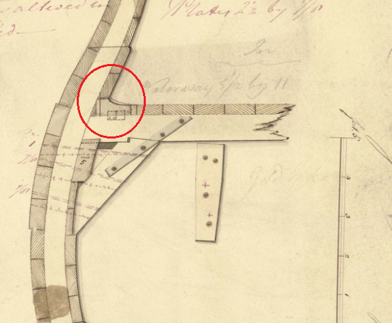
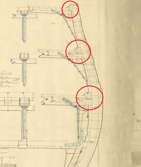
They are definitely different items. The waterway acts as a sort of gutter to help keep water from running between the bulwarks/deck and the framing. It is often modeled as some sort of molding like you might see between a wall and a floor. The waterways seen here look somewhat like the molding that is often modeled. The margin plank in practice, butts up against the waterway. I borrowed the images from a post by Allan in another topic.
- 840 replies
-
- winchelsea
- Syren Ship Model Company
-
(and 1 more)
Tagged with:
-
What glue to use
Gregory replied to David Enghauser's topic in Building, Framing, Planking and plating a ships hull and deck
I will say I do a lot of dry fitting before use the CA. -
What glue to use
Gregory replied to David Enghauser's topic in Building, Framing, Planking and plating a ships hull and deck
Another good resource is to look at logs for the NRG Half Hull Planking Project .. A lot of good tips on planking done right. -
What glue to use
Gregory replied to David Enghauser's topic in Building, Framing, Planking and plating a ships hull and deck
That is pretty much it. The bending will take place in two directions as it also has bend some latterly as well a vertically. Imagine a piece of tape on the surface of a sphere. -
What glue to use
Gregory replied to David Enghauser's topic in Building, Framing, Planking and plating a ships hull and deck
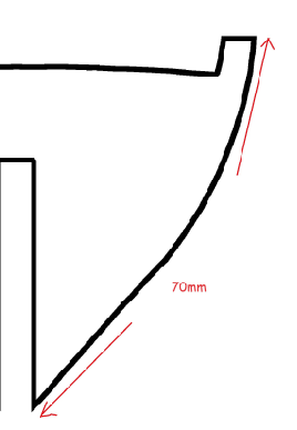
The tick marks are based on the width of the planks at a particular bulkhead and enable you to determine the taper of the planks. Typically the most full size planks would be found in the middle of the ship. ( amidship ) Imagine this is your middle bulkhead. I have marked the 5mm width of the planks ( not scaled ) and determined there are 20, with the bottom plank ( garboard ) being a little wider. That will have to be accounted for later. At the bow of the ship you will have a much smaller space to fill. Lets say the space for those 20 planks is only 70mm at the bulkhead closest to the stem. You would divide 70 by 20 to give you 3.5mm. So, your planks would have to taper from 5mm amidship to 3.5mm at the bow. Your tick marks at the bow would be 3.5mm apart. So, using some sort of tape, you would establish the width of the planks across the intervening bulkheads. You would duplicate the process from midship to stern. You might find at the stern you need more than 20 planks, in which case you would need wider planking stock, which is usually not provided in a kit, so you would have to introduce stealers, which might be better left for another discussion. I will try to find you some examples of people lining off the bulkheads with tick marks. Hopefully this will give you some information for starting the process. -
What glue to use
Gregory replied to David Enghauser's topic in Building, Framing, Planking and plating a ships hull and deck
While there are different preferences based on experience there are some excellent examples of people using CA here. A couple of my favorites are Glenn Barlow's Cheerful and Winchelsea. Chuck Passaro who has been very helpful with his planking tutorials, uses CA. Chuck is also a master model builder and designer. After following Glenn and Chuck for some time, CA has become my preferred planking glue. It takes some practice and care, but once you are comfortable with it, nothing beats it for speed, and all the clamps and clamping gizmos that go along with PVA are not necessary. CA has it's detractors for one reason or another, but it is very effective when used correctly. -
If you print them yourself you will be dealing with a dark outline of some sort no matter what, as well as something that will be very difficult to trim and match your back-ground color. If it's black you may be able to get a good match. How big are the letters? Here is a possible solution. Letter Number Decals for different scales Model Kits White/Black
-
Tiny "precision" drill press
Gregory replied to Ron Burns's topic in Modeling tools and Workshop Equipment
I don't think there would be any practical way to determine torque for these mini tools. It becomes a matter of sharing personal experience as to quality of performance.
About us
Modelshipworld - Advancing Ship Modeling through Research
SSL Secured
Your security is important for us so this Website is SSL-Secured
NRG Mailing Address
Nautical Research Guild
237 South Lincoln Street
Westmont IL, 60559-1917
Model Ship World ® and the MSW logo are Registered Trademarks, and belong to the Nautical Research Guild (United States Patent and Trademark Office: No. 6,929,264 & No. 6,929,274, registered Dec. 20, 2022)
Helpful Links
About the NRG
If you enjoy building ship models that are historically accurate as well as beautiful, then The Nautical Research Guild (NRG) is just right for you.
The Guild is a non-profit educational organization whose mission is to “Advance Ship Modeling Through Research”. We provide support to our members in their efforts to raise the quality of their model ships.
The Nautical Research Guild has published our world-renowned quarterly magazine, The Nautical Research Journal, since 1955. The pages of the Journal are full of articles by accomplished ship modelers who show you how they create those exquisite details on their models, and by maritime historians who show you the correct details to build. The Journal is available in both print and digital editions. Go to the NRG web site (www.thenrg.org) to download a complimentary digital copy of the Journal. The NRG also publishes plan sets, books and compilations of back issues of the Journal and the former Ships in Scale and Model Ship Builder magazines.

