Dan Vadas
-
Posts
3,261 -
Joined
-
Last visited
Content Type
Profiles
Forums
Gallery
Events
Everything posted by Dan Vadas
-
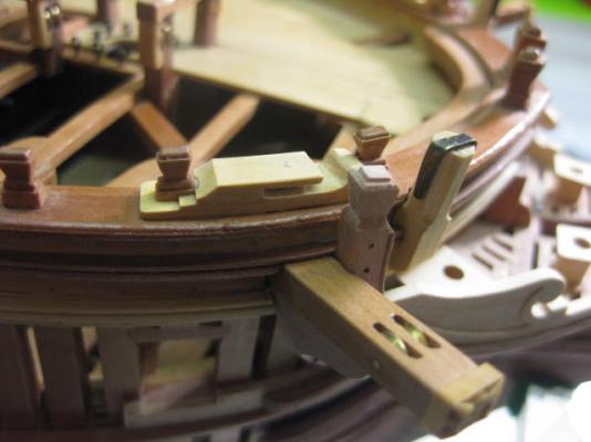
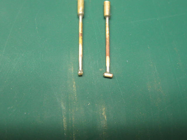
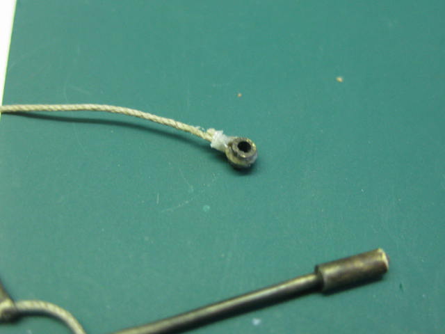
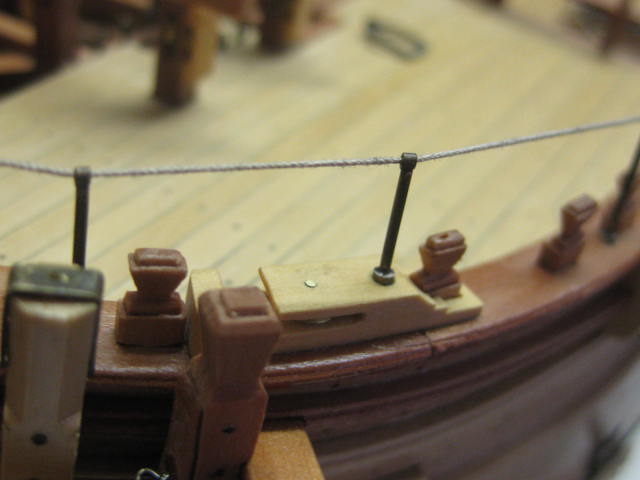
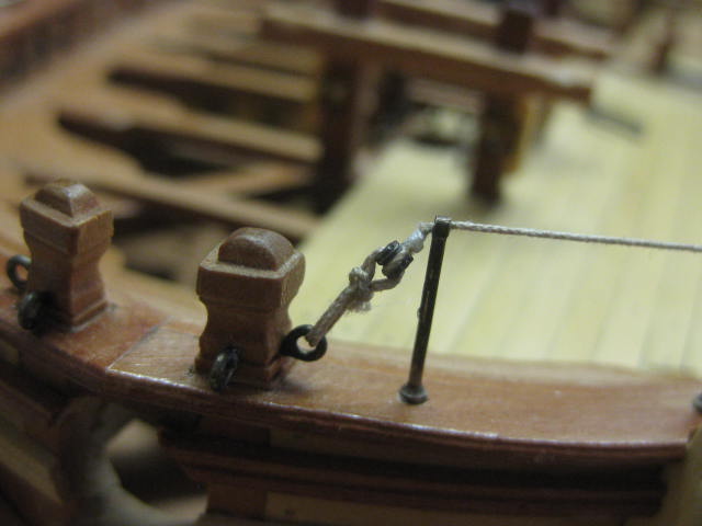
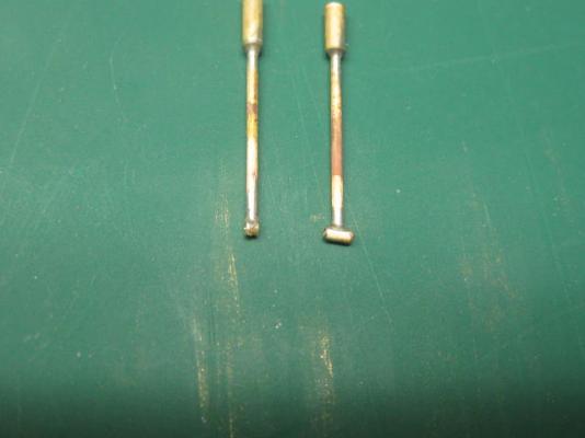
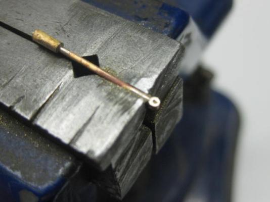
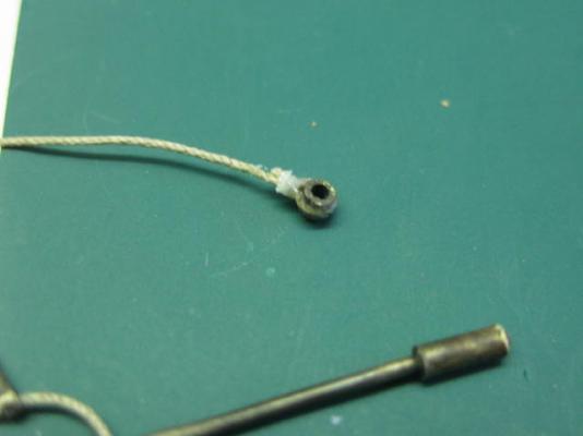
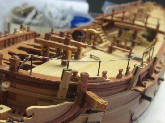
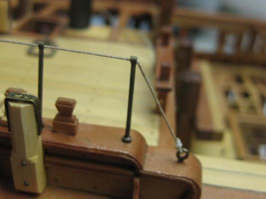
Thank you mhegazi, and a warm welcome to MSW to you Mark . Forecastle Railings I'm nearly at the stage of "Stepping" the Foremast, but I realised that it would be nearly impossible to fit the Forecastle Railings if the Shrouds were already fitted, so this was my next step. The Stanchions have a wide flair at the bottom, so to simulate that I silver soldered some 1.6mm tubing (ID of 0.85mm) to the bottom of some 0.8mm brass wire. I calculated the length of each stanchion first - none are the same length. Then I soldered a piece of 0.6mm ID tubing to the top of each stanchion for the Eye through which the rope will pass : I made the eyes a little on the large size to make soldering easier, then filed them down to the correct size : The top rope has an eye seized into one end, and a lashing at the fore end secures it : The aft end terminates with a seizing on an eyebolt : Danny


-
Thank you Popeye, Mark, Geoff, Adam and Jan. Mark, the Woolding Bands are thin (0.3mm) Manilla Folder card. I tried a couple of ways to make them from wood with no success. Thanks for the Birthday wishes sticlaru, Spyglass and Kevin, and also all those who PM'd me. Much appreciated. I'm afraid my computer is malfunctioning at the moment. I can't post any pics, so an update on my progress (and I've made a fair bit) may take a while until I fix the problem. Danny
-
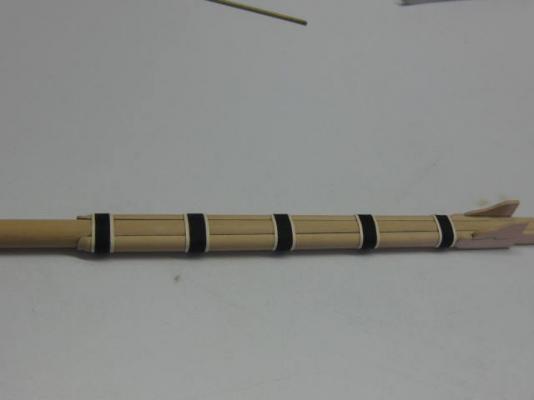
And thank you John . All the Wooldings and Bands are done. There is only one on the Mizzen Mast : Danny
-
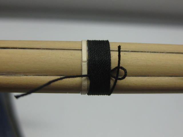
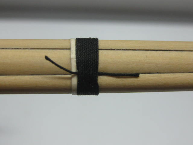
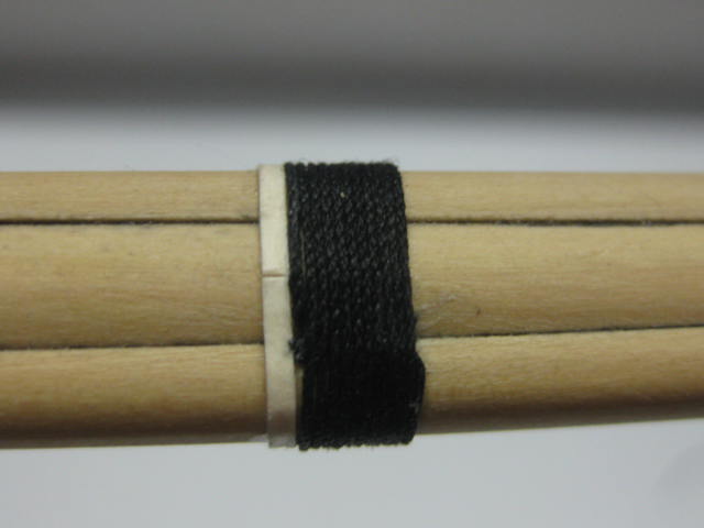
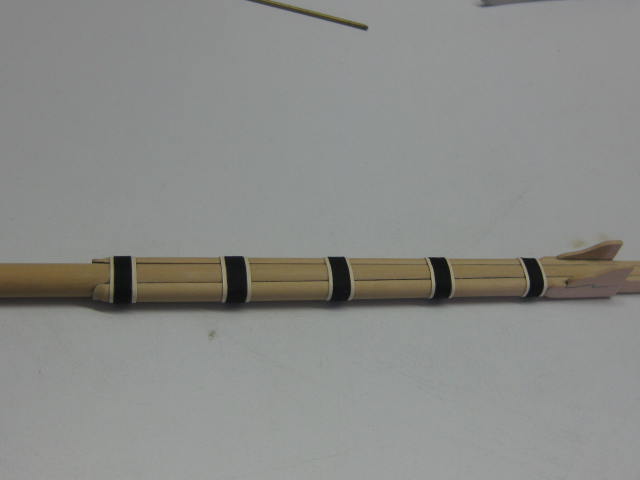
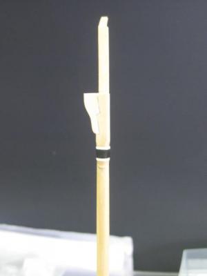
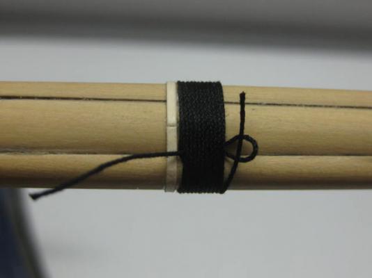
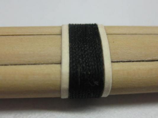
Thanks Grant and Pat. filing the square in the spanshackles must have been 'fun' Not too bad, but I'm rather glad I decided to only do the ONE . Wooldings My 0.3mm black rigging line has turned up from Chuck, so I can continue with the Wooldings. The pics below show the sequence of fitting them so they can't come untied : The upper bands were then fitted : Danny


-
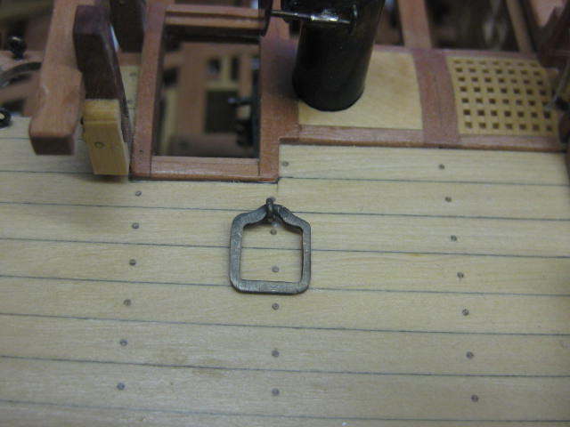
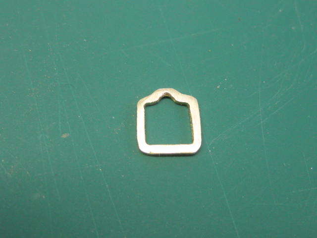
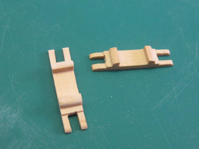
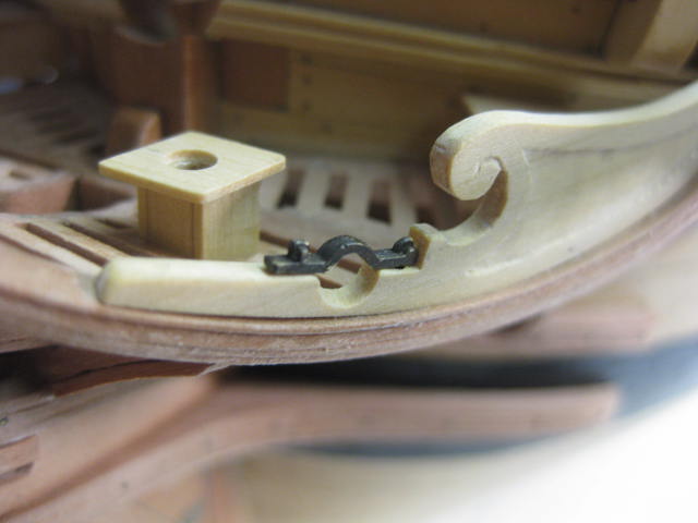
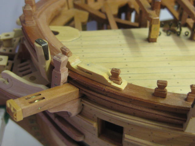
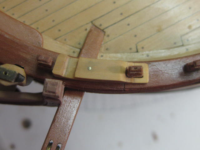
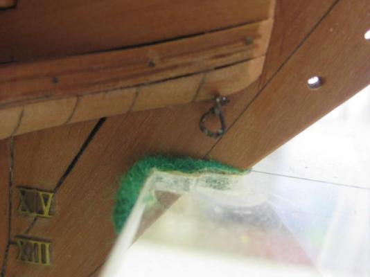
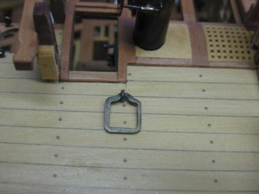
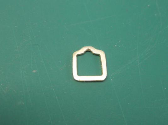
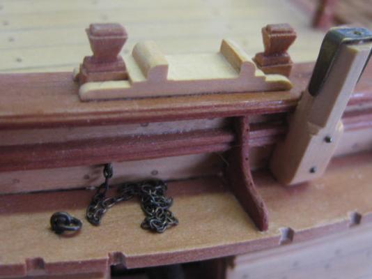
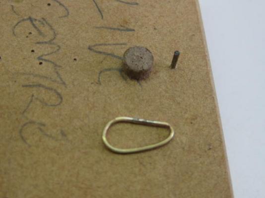
Thank you Geoff and E&T. Ironwork in the Head A few more eyebolts needed to be fitted in the Head for the Jib rigging. One of these (or rather two) are the Bookmin Lashing Ringbolts, which are triangular in shape : Spanshackle Ring Another interesting piece of ironwork is the Spanshackle Ring, of which I am only fitting the port side one. This "ring" is a square section piece of iron which supports the Fish Davit when it is in use. I drilled and filed the centre out from flat sheet - the lower section has a dogleg around the eyebolt which needed rounding off : Fish Davit Cleats And finally I made the two Fish Davit Cleats which support the davits at the railing : Danny

-
Hi Mike, Glad to see you have completed the Standing rigging - everything looks as it should . BTW, I confused myself in the PM reply earlier - the kit I was referring to that had the garbage rigging diagrams was AL's HMS Supply, not their Bounty which had quite good rigging plans. I think I still have them somewhere, so if you need any help with the Running rigging feel free to ask. In any case, the only things that change from ship to ship in this period are some of the belaying points - most other rigging is pretty well the same. Danny
-
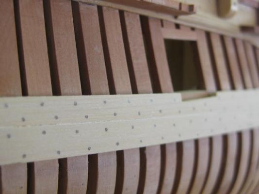
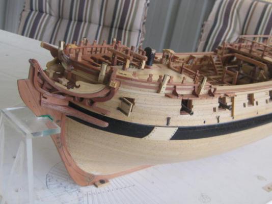
Thanks vths, Bill, Remco (yes, I found the Masting Plans ), Pat and Julian. Starboard Side Black Strake I've fitted the "black" strake and the one above it to the Port side so that the Chains have something to attach to. I've also finished treenailing both : Danny
-
And thank you Harvey, David, Tony, Cog and Ben. Good question - I don't remember if I did or not . I'll find out tomorrow when I pay a visit to my daughter's place where some of my stuff still is, but I hope I did . EDIT - Yes I did Bolsters The Bolsters sit atop the trestletrees and ease the angles of the Shrouds and Forestays over them to prevent chafing : Danny
-
And thank you too Geoff and Jason. Cross Trees The Cross Trees are the Top supports that run athwartships. All the work in cutting the rebates was done on the Byrnes saw, and the tapers were done on the disc sander : Danny
-
In that case, make 20 or 30 and pick out the best ones - it costs nothing , and you'll soon get the hang out of stretching the stuff to close tolerances. Danny
-
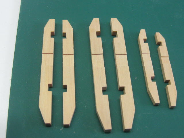
Bibs The Bibs were made next and fitted. As with everything else on the masts the sizes are all proportional to the mainmast : The Mizzen Mast has a very abbreviated pair of Cheeks : Trestle Trees The Trestle Trees took quite a bit of working out to get them spaced correctly. Unlike the earlier volumes of TFFM there are almost no detailed scale drawings of the various parts needed for the masts, and everything has to be calculated : Danny


-
Thanks once again for the kind comments Tony, Nils, Spyglass, Hjalmar, Mark, David, Christian, Remco and Steve, and all the "Likes". Always appreciated. Mast Cheeks The Foremast and Mainmast both have Cheeks fitted to each side of the mast. These extend from the top of the Hounds to about 3/4 of the way to the deck. The Hounds are incorporated in them at their top - something I'd always puzzled about in previous builds, but now have become clear . First the mast had to be narrowed to accommodate them, all the way to the top : Next I tapered the cheeks to the same width as the flats on the mast, half-rounded them to the bottom of the hounds, and cut in the scarf joints for the Bibs. As the bibs are thinner than the hounds the scarf joints were cut in to their thickness : The bottom of the cheeks were shaped into a "duckbill", with the inner face scalloped out for the last couple of millimetres : Filler pieces were then glued to the masthead and tapered : A tenon for the Cap was cut into the top of masthead at an angle. In real practice this was done to prevent the very heavy cap from tilting down at the fore end : The lower Woolding Bands were made from thin card. They measure 0.8mm wide by 0.3mm thick. The wooldings will be added when my next stock of rigging thread arrives, and an upper band will finish them off : Danny


-
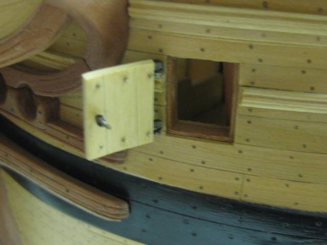
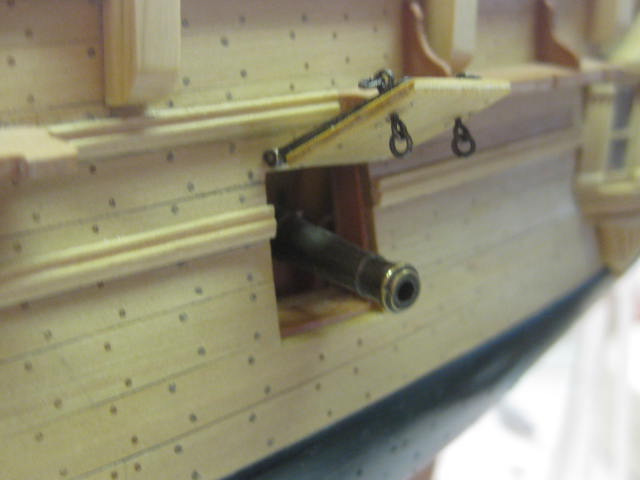
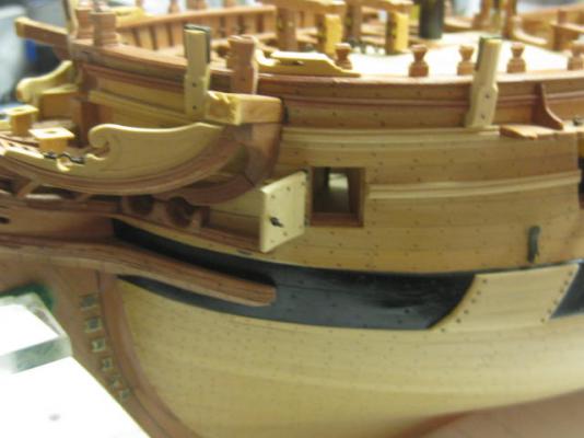
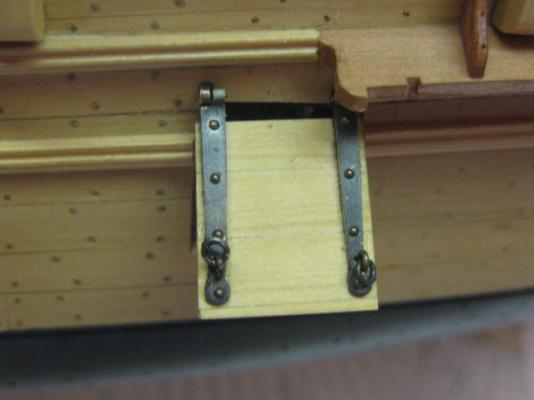
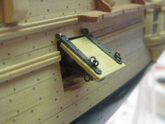
Thanks again John, Vivian, Michael, John and Greg - your comments are always appreciated. Bridle Port Looking through the above pics I realized I'd forgotten to mention the Bridle Port. This port is the foremost one, and is quite a bit different to the gunports. It's main function was to assist in attaching the tackle to the anchor when it broke the water so it could be stowed. An ancillary function was to provide ventilation below the foredeck which houses the galley, the manger and in some ships was used as a recovery area for sick or injured crew. Unlike the gunports the bridle port is hinged horizontally. It's construction was otherwise similar to the gunport : Danny

-
Thank you Remco, John and Allan. OK Remco - you asked for it : There are four supports Allan. They work fine at the moment, but as I get into the smaller sizes I'll remove a couple of them and replace them between a couple of the existing ones. BTW - this jig came with the Masting Package. Danny


-
Announcing the Model Ship World Ship Kit Database Project
Dan Vadas replied to SkerryAmp's topic in Wood ship model kits
I had no problem copying and saving a pic of the "Lark" from their Gallery. Maybe just a temporary glitch on your end ? EDIT - Apparently you can't copy the pics attached to their Kits (some of them are pretty crappy pics anyway). Try the Gallery - there are four good pics in there. Or do a Print Screen and edit it. Danny -
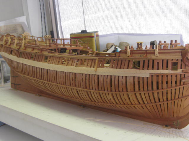
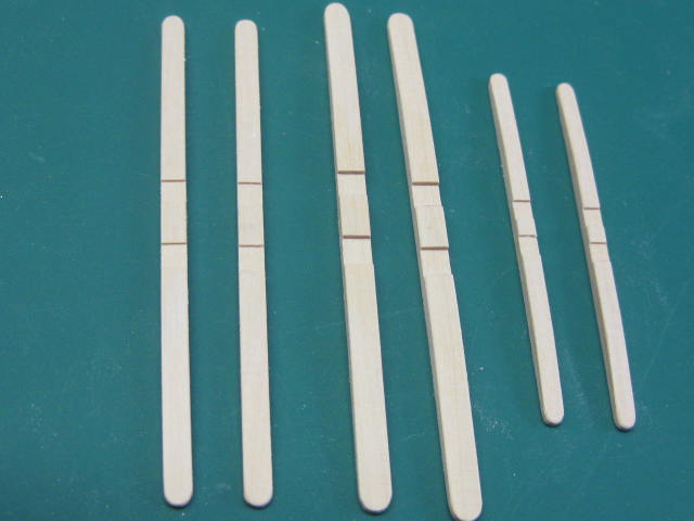
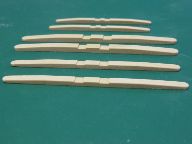
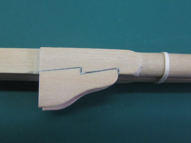
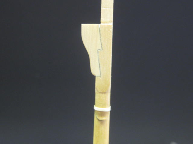
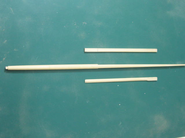
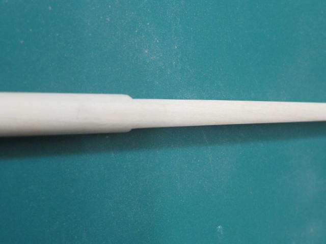
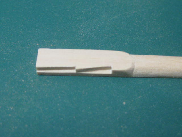
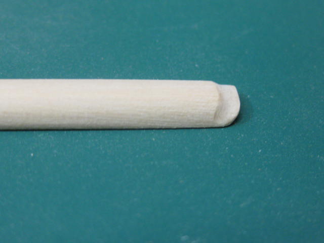
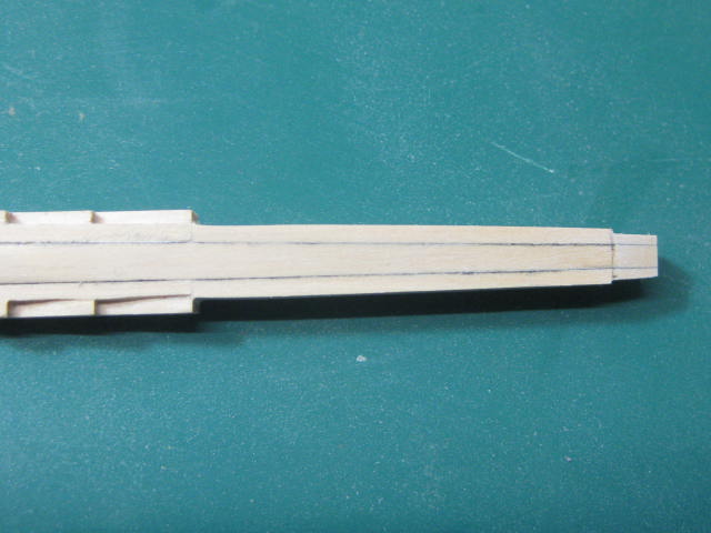
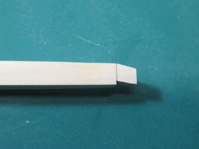
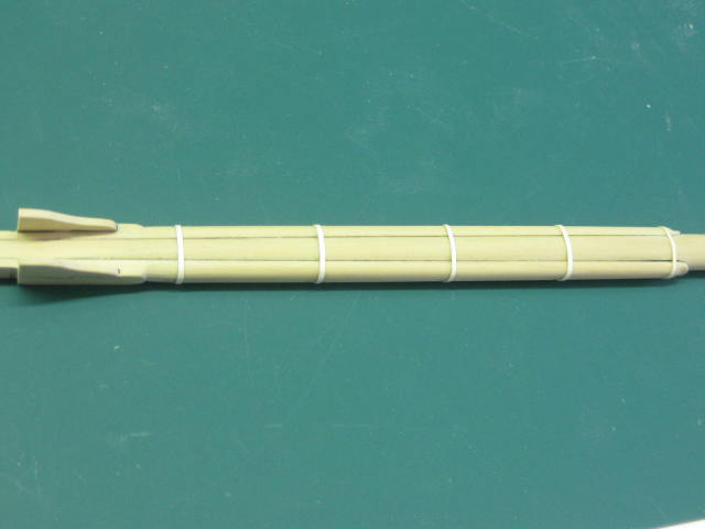
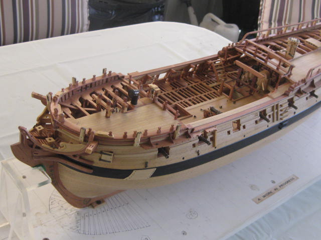
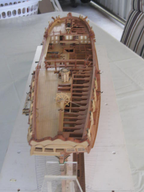
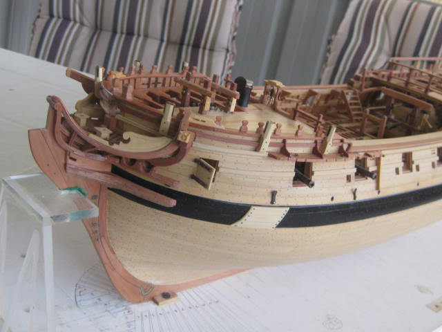
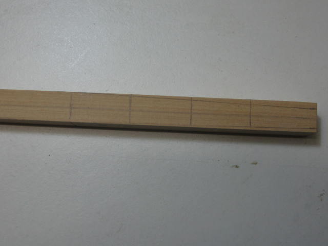
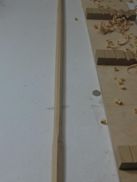
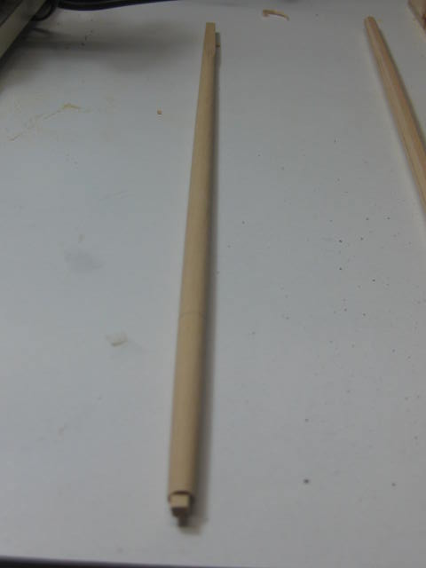
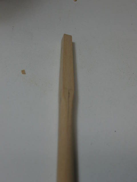
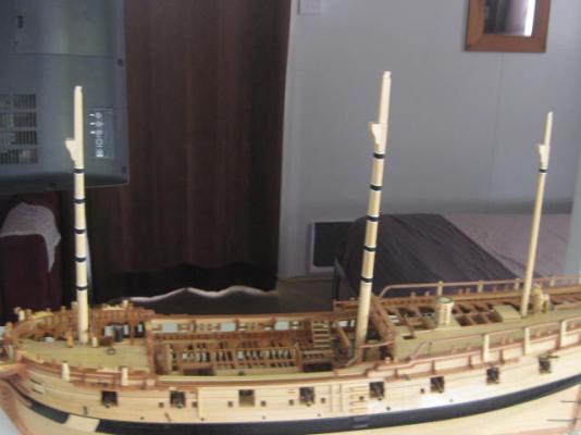
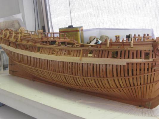
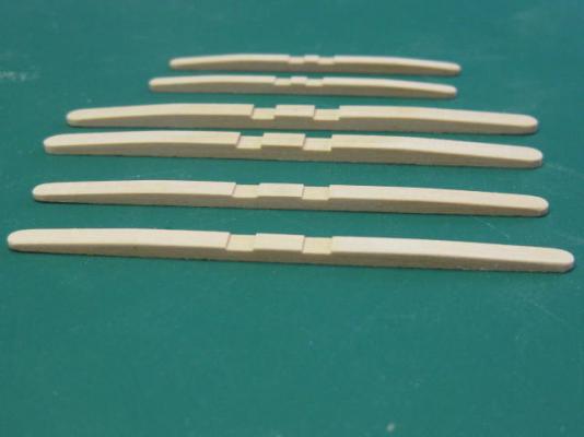
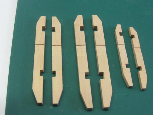
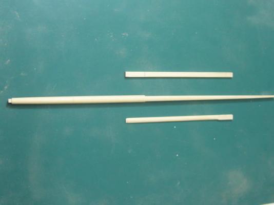
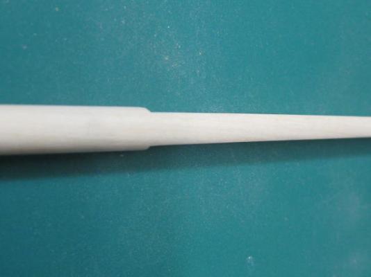
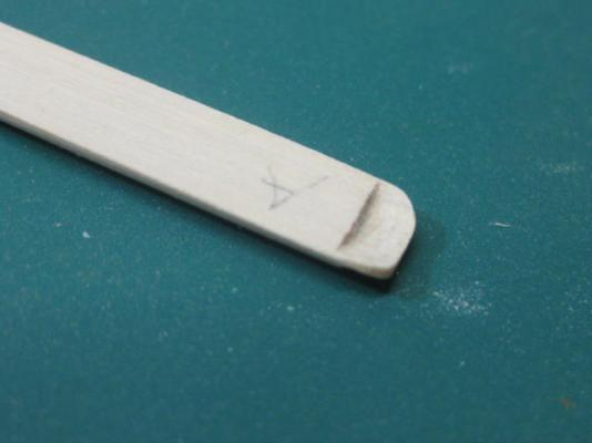
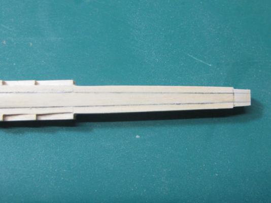
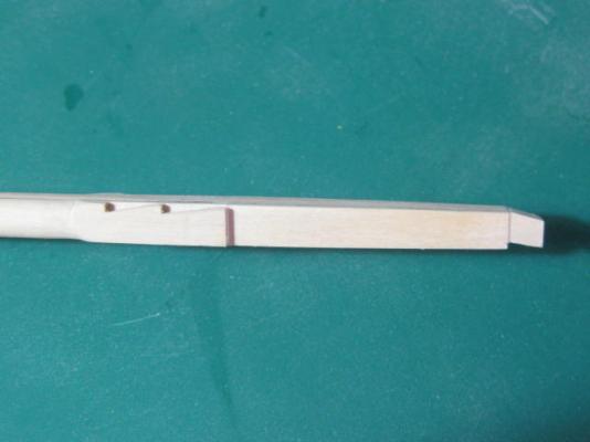
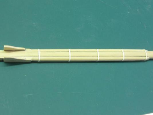
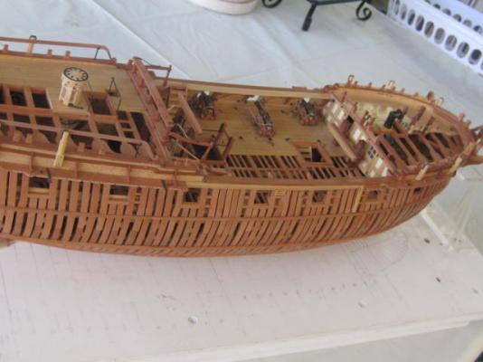
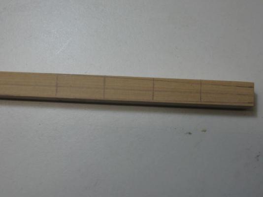
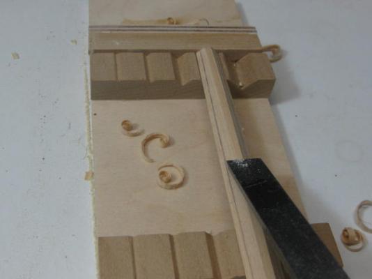
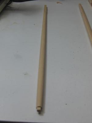
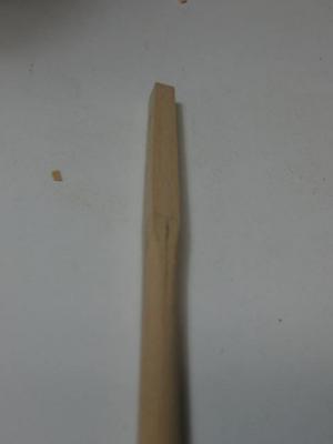
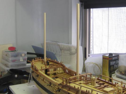
Thank you for dropping in again Remco, Nils and Ben . Lower Masts Sometime soon I'm going to need the Masts for alignment purposes to go ahead with fitting the deadeyes to the channels. Up until now I've "made do" with a couple of "dummy" masts, but now it's time to make the real things . I was lucky to buy one of the last of the Masting Packages for the "Swans" from Hobbymill about a year or so ago. As usual, Jeff's timber and packaging is EXCELLENT - there are TWO pieces supplied for every part needed in case of "oopsies" (I've already made one ). The masts (and just about everything else) starts out as square stock - no dowels in this lot, that would have been counter-productive . Following usual practice for making "round" masts from square stock I marked out two sides with the taper required. I've also tapered the masts below deck as per the original. The pic below shows the marking out for the section between the Partners and the Heel : After tapering these two faces with a chisel and sandpaper I marked out the other two and tapered them as well. Then I marked out each face for the edges where the "octagonalling" would finish. I cut the tapered square section into a tapered octagon using a "V" jig and a sharp chisel : Then I rounded the octagon using a sanding block, and cut the lower tenon into it : The Mast Head remains square for now - much more work to be done here later : Fore and Main Lower Masts fitted to the ship : Note - I had to make two Main Masts (the oopsie mentioned earlier). I'd made the main mast a bit too thin at the partners on the 1st one and wasn't happy with the result. Just as well that Jeff had supplied plenty of timber . Danny

-
G'day Jaydee, A trick I used back in the days when I was into plastic models was to heat and stretch some of the sprue that the parts are molded onto to make rigging "thread". You can draw this out to amazingly thin section. Use a candle or similar to heat the sprue, and then simply pull at each end until it's as thin as you need it. Glue it to each end of the brace and trim it with a sharp knife when it sets. Hope this is of help to you. EDIT .... DOH, Jay beat me to it while I was typing this post . Danny
-
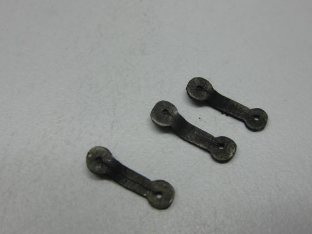
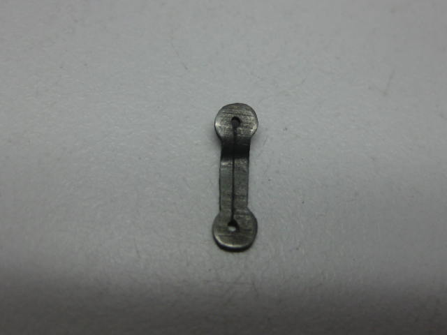
Thanks once again for the kind comments Geoff, Nils, Grant, Pat, Michael and Mark . Here's a pic of a completed deadeye with chains. The deadeye was fitted after the chains were soldered and blackened by clamping the deadeye in the vise and squeezing the upper link tight with needle nose pliers : I've made all the various size deadeye/chain assemblies. The last of them are pickling in vinegar at the moment, prior to blackening. Preventer Plates I've also made the 32 Preventer Plates, which fit to the lower end of the lower links on the Fore and Main shrouds. The plates were made by drilling the 0.6mm holes 7mm apart in a strip of 3mm x 0.8mm, and then filed to shape. A line was marked between the holes to simulate the way they were originally made - the piece was forged from square bar on the original. A dog-leg was then bent into the upper end to give clearance for the chain from the hull. I made a simple jig by taping a piece of 0.8mm plate to the top of my small anvil. Another thicker plate was then placed over the piece and tapped a couple of times with a small hammer to make the first bend, then the other bend was tapped in by hitting the end of the piece : Danny

-
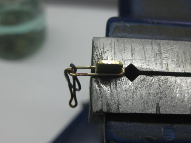
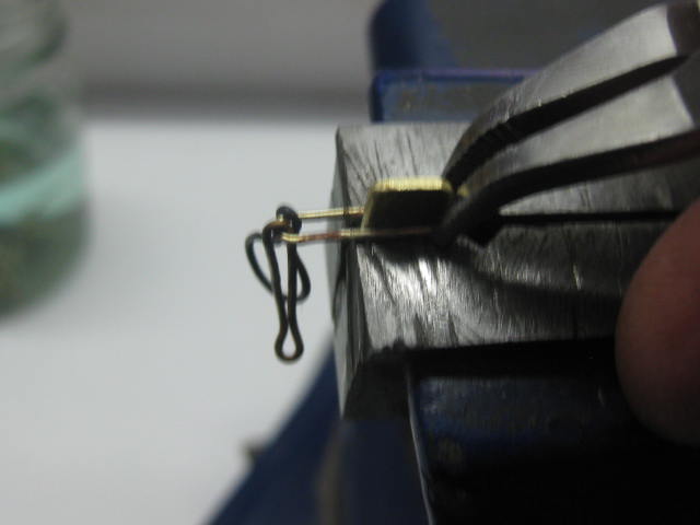
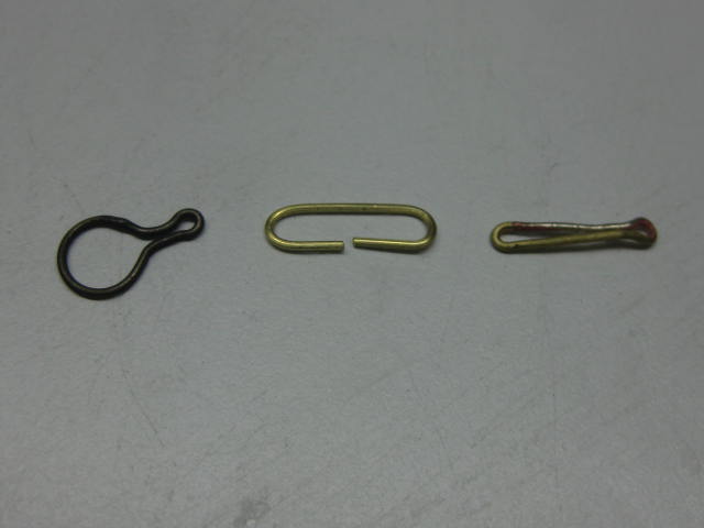
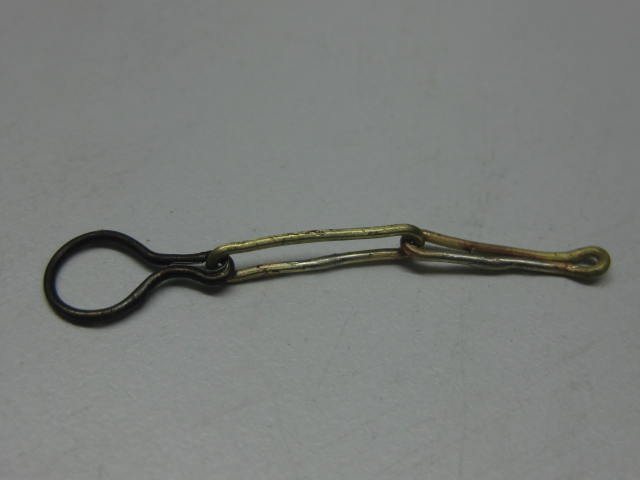
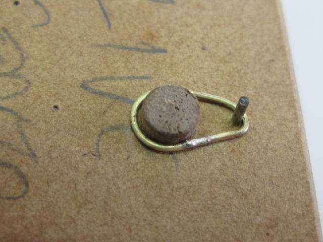
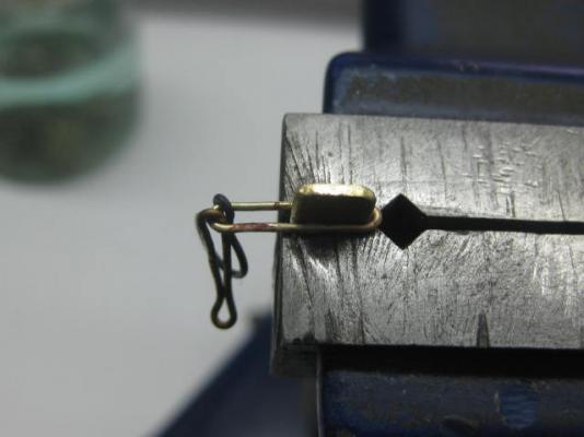
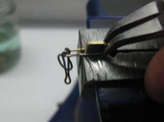
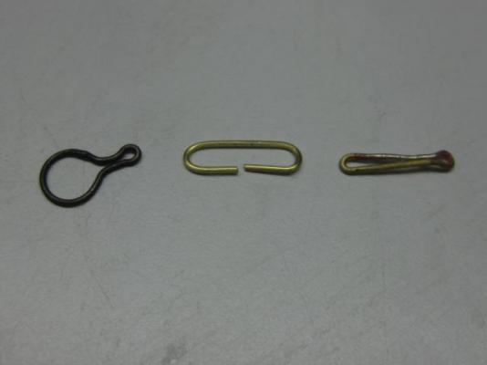
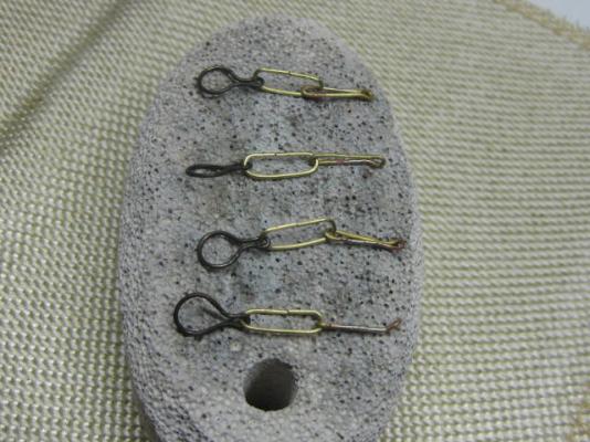
..... continued. Thanks Michael. I use a mini gas torch for all my soldering, and silver solder paste. It flows beautifully, but the joins MUST be a zero fit as it won't fill any gaps. The Middle Links and Lower Links were both made by first cutting all the pieces to length - oddly enough ALL the links finished up the same length of 28mm, even the upper links. According to TFFM the middle lengths should have been of varying lengths to allow for the change of angle, but as they also sweep up slightly as the go aft the difference was so minimal (0.2mm) that it didn't warrant a whole lot of extra work . To bend the pieces I used a simple two-nail jig. The lower links were then silver soldered and shaped around a 1mm drill bit at their lower ends. The upper ends were finessed with pliers around a wedge shaped piece of brass held in the vice similar to the one shown here : The three links ready for final fitting : Once the lower links were soldered and shaped the middle links were fitted between them and the upper links and soldered together. The middle link was then tightened down using the jig shown above : I use a piece of pumice stone ($4.00 from a supermarket) to hold the pieces for soldering. Danny
-
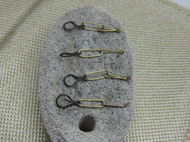
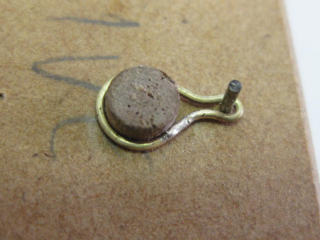
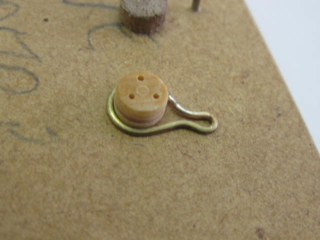
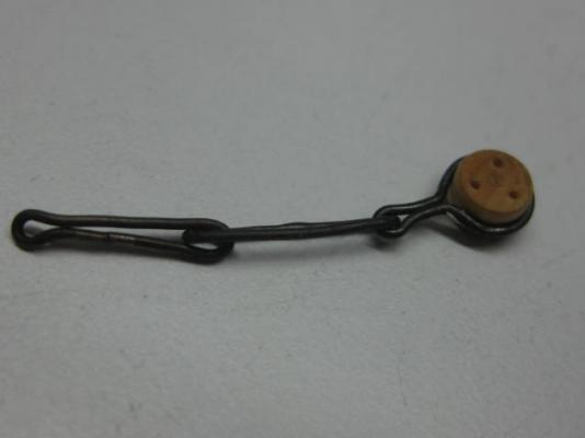
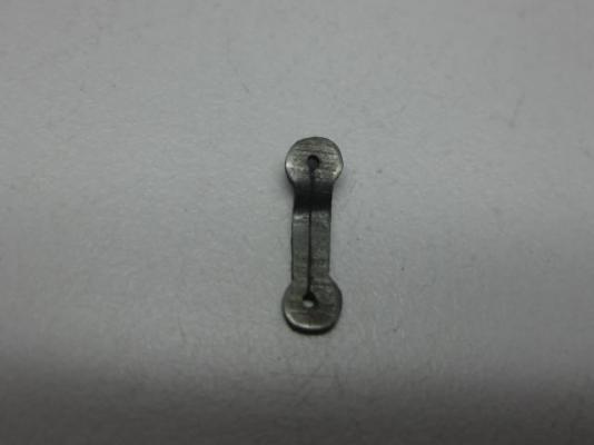
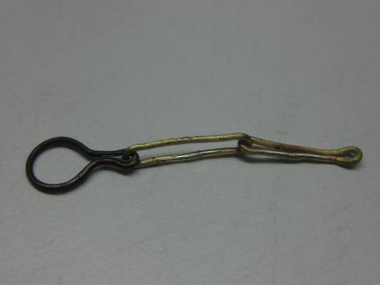
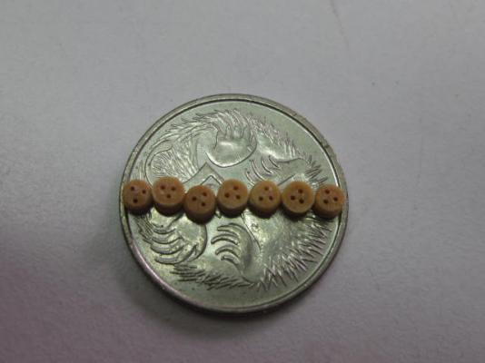
Thank you Brian and John. Which means I can fit 7 of the 5" deadeyes across one and still have room to spare : Chains Construction of the Chains - the "support braces" for the lower deadeyes - begins with the Upper Link or Deadeye Binding. As it's name suggests this is a forged steel binding which wraps around the deadeye. It passes through the channel and has a loop in it's lower end which attaches to the Middle Link. To make these, which are all the same for this size of deadeye, I used a jig. The 0.7mm brass wire was first bent into a rough oval and the join silver soldered. Then it was tightened around the wooden pin and nail with needle-nose pliers to form it's shape : The wooden peg in the jig was turned down to give a push-on fit over the outer diameter of the deadeye. Final fitting was accomplished with needle nose pliers. I needed to make one up to measure the following links - this one was later opened up and the deadeye removed prior to blackening of the wire : Continued next post......


-
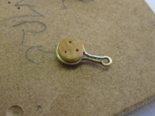
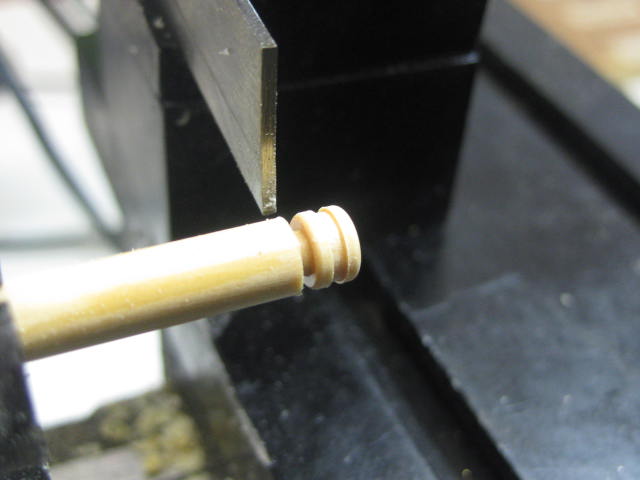
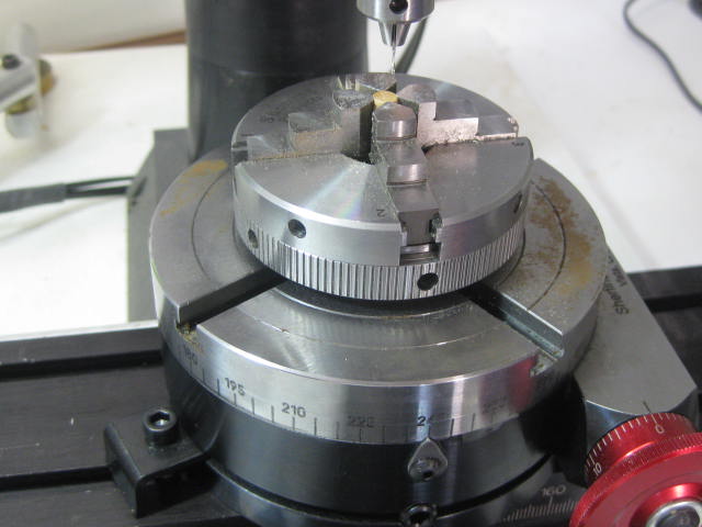
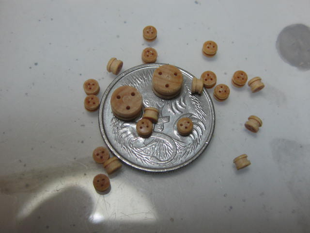
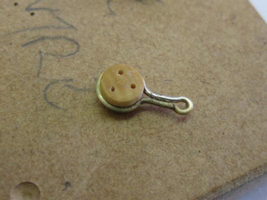
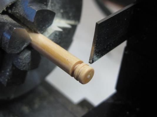
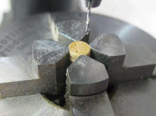
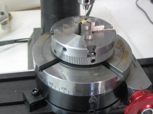
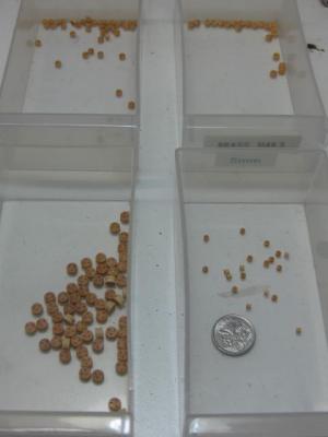
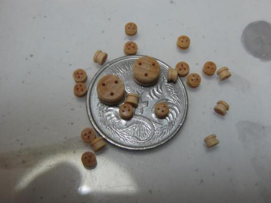
My sincere apologies for not posting sooner - my computer was either very sick or dead these past few weeks - all fixed now . Thank you for your replies Allan, Druxey, David, Mark, Doris, David, Crackers and Johann, much appreciated. Of course it would have Allan (and David , but you must have missed my comment regarding that bit - I didn't have any tubing of the right size, and to get some would have meant a 1 hour round trip with no certainty of success in getting any from the "local" hobby shop . I figured correctly that I could file the hinge straps in about the same time . Deadeyes Although my computer has been down I haven't been idle. I've turned ALL the Deadeyes and drilled them as well - all 142 of them, in four sizes - 64 off 10" (real size) or 5.3mm, 20 off 8" (4.25mm), 42 off 7" (3.7mm) and 16 off 5" - a tiny 2.65mm, the holes were a lot of fun to get right in these ones . First, an explanation of why I made my own when there are very good quality ones available from companies like Syren Ship Models and some of the Russian sites. While these are of very nice quality, none of them had them in the sizes I needed. For example Chuck supplies all of his in even millimetre sizes (with good reason) and I thought the differences in some of the sizes I needed would have been too great and noticeable. For the 8" and 7" deadeyes I would have had to go with a 4mm deadeye for both, as you can see from the previous paragraph. The 5" deadeyes would have been either too large or too small. Besides - I like a challenge . After turning the diameter of the "huge" 5.3mm deadeyes I used a 1mm Parting Tool to cut the groove and also part it from the stock - the Digital Readout came in very handy to keep them all to exactly the same dimensions. For the 7" and 5" ones I ground an old parting tool down to 0.7mm. I rounded the edges with a needle file : To drill the three 0.6mm holes for the 10" and 8" ones I used my new Rotary Table in the Mill. The holes are 1/4 of the way in from the outer edge and are spaced evenly at angles of 120 degrees apart. The 7" and 5" deadeyes have 0.45mm holes : All the deadeyes separated into sizes : An idea of the small sizes of them. Some 10" and 5" deadeyes on top of a 5 cent piece : Danny

-
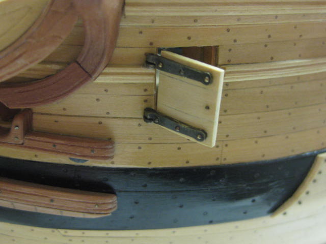
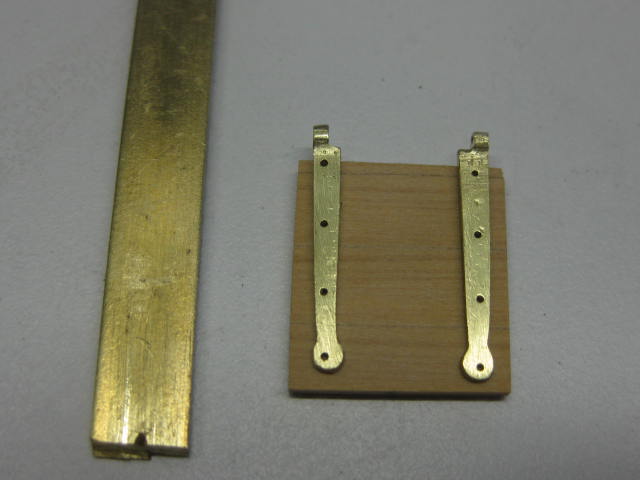
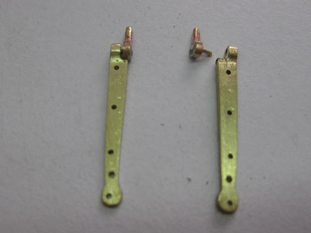
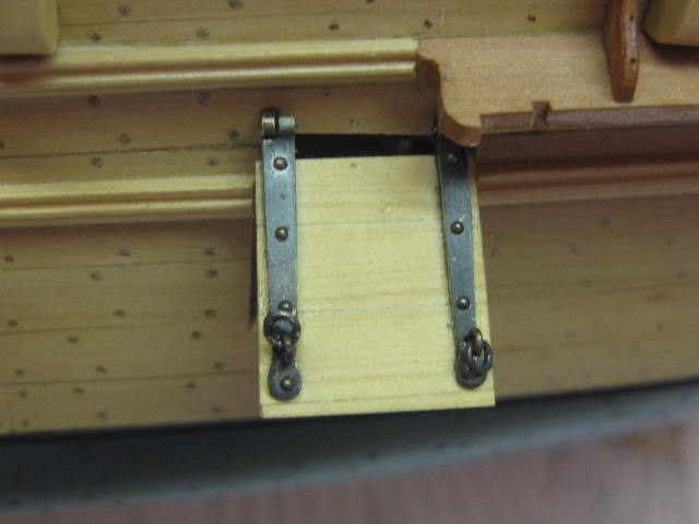
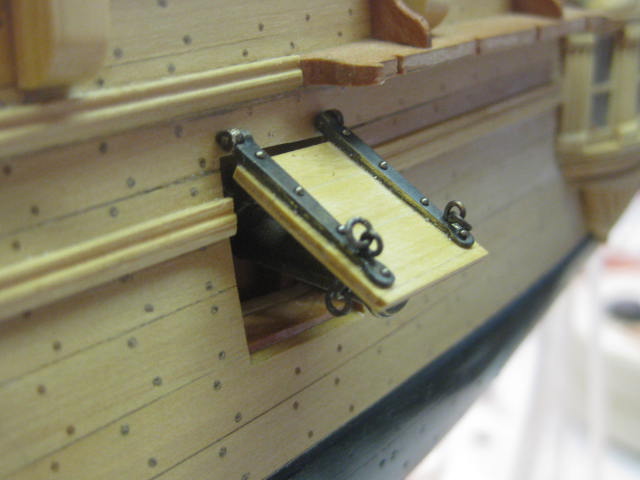
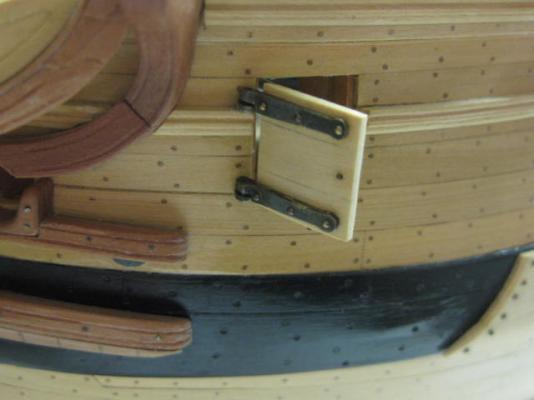
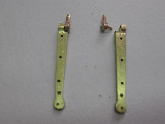
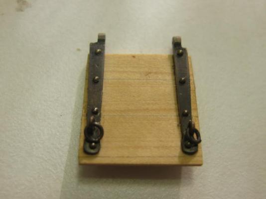
Gun Port Lid There is only one gun port lid on each side of Vulture - the aftmost one, or Number 8, which is in a cabin. With the exception of Number 1 which is in the Forecastle the others are all more or less open to the elements and don't need them. I'm surprised that Number 1 port doesn't have one. I'm rather glad I didn't build a Victory - I'd have needed to make a few more . This one port with it's hinges took me three days . The only other port I'll be making will be the port side Bridle Port, it's a little bit easier as it doesn't have as many eyebolts and rings. No port lids will be fitted to the open starboard side. I made the hinges from a piece of 2mm thick brass strip, and incorporated the knuckle into it by filing rather than soldering a separate piece on (I've run out of suitable tubing). The majority of the work of removing the surplus was done with the disc sander, the rest with needle files. I drilled the holes for the bolts and the hinge pin just after tapering the top face, while the piece was still attached to the rest of the strip. This made clamping to the mill vice easier : The Hooks (the other part of the hinges) were made in similar fashion. I silver soldered the pins to them after first drilling holes for them : The Port Lid itself was made by cross-laminating seven pieces - the external face has three and a bit planks which follow the run of the hull planking, and the internal face has three planks which are fitted vertically. After blackening the hinges they were epoxied and pinned to the lids. I used 0.8mm round-headed pins (shaft diameter of 0.4mm) : Eyebolts and rings are fitted both inside and outside for the port tackles - these will be faked as there is no way that they can be fitted at this late stage of the build : The hinges REALLY WORK : I'm off to the Port Macquarie Model Show in the morning - I've got Vulture almost exactly to the stage I'd planned on a couple of months ago for this show . Danny


-
This Index continues on from the one on Page 1. To return to the first Index click HERE Head Works Lower Cheeks Hair Brackets Wash Cants Bolsters Gammoning Chocks Main Rails Head Beam and Grating Battens Head Timbers Saddle False Rails and Aft Seats of Ease Cathead Supports Eking Rail Gun Port Lid Bridle Port Figurehead Masts Deadeyes Chains Preventer Plates Lower Masts Mast Cheeks Bibs and Trestle Trees Cross Trees Bolsters Starboard Side Black Strake Iron Work in the Head, Spanshackle Ring and Fish Davit Cleats Wooldings Forecastle Railings Berthing Rail Billboard Mast Heads and Caps Topmasts Topmast Trestles and Crosstrees Topgallant Masts Cheek Blocks Bowsprit Hearts Standing Rigging Collars Bobstays and Bowsprit Shrouds Gammoning and Boomkins Fore Tack Step Blocks Main Stay Collar Mizzen Mast Shrouds Mizzen Mast Forestay and Collar Main Mast Lower Shrouds and Burton Pendants Fore Mast Shrouds Main Stay Main Preventer Stay Fore Stay and Preventer Stay Mast Tops Making Blocks Blocks under the Tops Top Stanchions and Railings Catharpins Euphroes Crowsfeet Futtock Shrouds Ratlines Shroud Cleats Mizzen Topmast Shrouds Mizzen Topmast Stay Main Topmast Shrouds Main Topmast Stays Topmast Futtock Staves, Fore Stay and Preventer Stay, Topsail Yard Tyes Topmast Ratlines Topgallant Shrouds and Stays Jibboom Crupper and Jib Traveller Jib Net Jibboom Horses Fore Topgallant Stay Jib Stay Mast Trucks Yards and Running Rigging Spritsail Yard Jeer Tyes Topsail Sheet Blocks Blocks fitted to the Lower Yards Stunsail Irons Truss Pendant Tackles Spritsail Running Rigging Crossjack Mizzen Mast Cleats Gaff Jeers Yard Lifts Main Stay Tackles Topsail Yard Tyes Parrels Topsail Yard Lifts Topgallant Yard Parrels Vangs Braces Lantern Anchors Fish Davit Swivel Guns Waist Rails Hammock Cranes Anchor Rigging Clues, Tacks and Sheets Fitting Hammock Cranes Fitting Swivel Guns Flags Fitting Stern Lights Part 1 Fitting Stern Lights Re-Do Fitting Capstan Bars Pedestals Rope Coils Lantern Braces Binnacle .
-
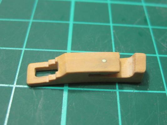
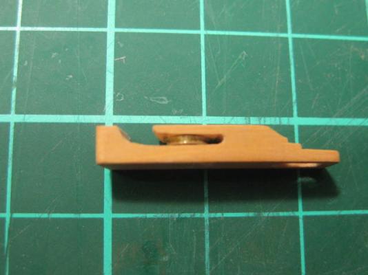
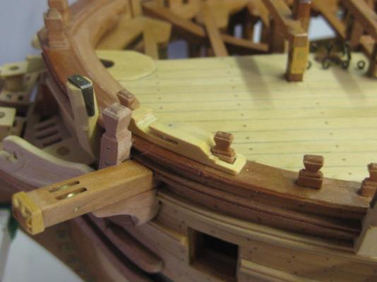
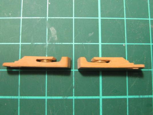
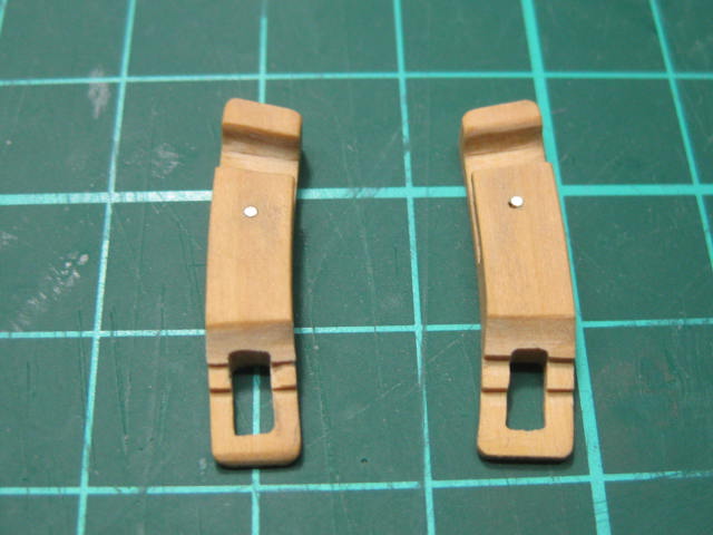
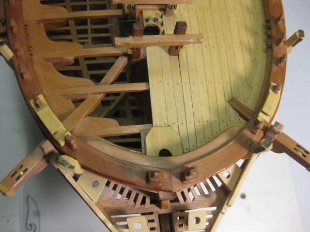
Thanks again Geoff . Cat Block for the Falls The function of the Cat Block for the Falls is to lead the Cat Fall line (which is used to raise the anchor) to a horizontal plane. This enables numerous hands to haul the anchor up. This is a Snatch Block - it has an open end, enabling the line to be fed on without the need to reeve it through the block. I made these from English Box. A brass sheave is fitted to each. It took me the best part of a whole day to make the two of these : Boomkin Capsquares I've also cut the recesses for the Boomkins, and temporarily fitted the Capsquares. These are once again made from two leftover capsquares from the guns. They needed a little modification to fit around the 8" boomkin : The boomkins won't be fitted until a bit later in the build, as they will interfere with the Gammoning of the bowsprit. Danny