


allanyed
-
Posts
8,149 -
Joined
-
Last visited
Content Type
Profiles
Forums
Gallery
Events
Everything posted by allanyed
-

Excellent How to Book for masting and rigging
allanyed replied to Bill Morrison's topic in Masting, rigging and sails
Bill, congrats on having had this book given to you. It has been my go-to book for rigging for years as it covers all types of English ships and a very wide range of time. The ratios in the back of the book allow anyone to properly size masts, yards, standing and running rigging based on the size of the vessel and the time she would have been in service. Allan -
I like the finish you put to the sheathing and that they designed the plating to be overlapped. This is definitely far better than nearly all of the sheathing we have all seen on the build logs. The only thing that I don't understand is why Amati made the nails triple the diameter that would be in actual practice. I scaled your photo to full 48"X15" plates and the etched circles are 1.5" diameter versus the actual 0.5" they would be. As they are etched it seems that the manufacturer could easily do this at the proper scale by just etching a round dot instead of an oversized ring. I have minimal experience in metal etching, but it seems this could be done whether chemically or laser etched. Great job David, your build continues to be a joy to follow. Allan
-
https://www.rmg.co.uk/collections/objects/rmgc-object-68763 shows these on the model at RMG but there are no lines running through them. I thought they might be sheaves for lines to pass around and through the bulwark, but now not so sure. Allan
-
Your build continues to be a joy to follow. One seemingly small thing that is actually quite significant is the use of paper or card stock patterns which cost nothing to make and save a lot of time by minimizing mistakes with the wood. Allan
-
Welcome to MSW Iron Hands. Hope your touch is lighter in actual practice when working on your model😀 You may very well be the youngest member here and it is great to see. I hope you can deal with over 40,000 new teachers and maybe half as many different opinions at times. Truth is we are all still learning, even though many of us have run the guantlet many times already. Allan
-
Dave, From Caruana, volume 2, the swivel guns had been 3 feet long as standard until about 1727 then barrels of 30" became the British navy standard for 1/2 pounders. For the LN, 2.5 foot long barrels would be most appropriate so at1:64 they would be just under 1/2" long. The ones from Syren look great but are huge compared to what you require. Allan
-
FWIW, I think Katsumoto has given the best advice, remove the planks and start over. It is hard to tell from the photo but it appears the garboard runs too far up the stem. It should end at about the forward end of the boxing joint otherwise the planking winds up looking like a Viking ship and there is not enough room to fit the planks unless you taper them too much and use a lot of drop strakes. If done properly, there is no need for more than one or two drop strakes, if any at all. Good luck. Allan
-
Valky THANK YOU You are doing a great service to the membership and I am looking forward to the next report. Looks like the Japanese tempura paper might be the winner so far as there is no out of scale weave to contend with. Do you know if it works well with matte medium like silk span does? Allan
- 35 replies
-
- 2
-

-
- Constitution
- Revell
- (and 1 more)
-
Treasure Galleon La Nuestra Señora de Atocha, 1620
allanyed replied to davos522's topic in Nautical/Naval History
Great read for anyone interested, thanks for posting this. Definitely need to make plans to drive over for a visit to the museum, the many bars, and maybe do a little fishing as well.😀 -
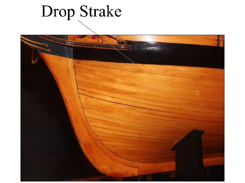
If they are needed, normally there are stealers at the stern area as the planks widen as they move aft and drop strakes towards the bow as the strakes narrow. The below shows a drop strake on a contemporary model at Preble Hall. Allan
-
SOLEIL ROYAL 1669 by michel saunier
allanyed replied to michel saunier's topic in - Build logs for subjects built 1501 - 1750
Thank you very much for posting these photos. If ever there was an inspiration in ship modeling, this is certainly a top contender. Allan -
Size of Rope and Serving for Stropping blocks
allanyed replied to Peter6172's topic in Masting, rigging and sails
I think this one of those things where only a Wabac machine or time machine will allow us to find out the facts. I find Caruana to have done far more research than anyone regarding British ordnance, but that is not to say there are no mistakes in his volumes. Cheers Allan
-
The tutorials for spiling by David Antscherl or the heated edge bending by Chuck Pasarro show that the top and bottom curve. As to asking for help, after 40 plus years of scratching I still find myself asking what I feel are basic questions at times so fear not. If you cannot find an answer with doing your own research, MSW has always been a great place to get questions answered. Allan
-
Size of Rope and Serving for Stropping blocks
allanyed replied to Peter6172's topic in Masting, rigging and sails
Just a little side note Peter. Only 32 pounders and larger used a single and double block. For both running out and training tackle, all guns smaller than 32 pounders used two single blocks. (Caruana The History of English Sea Ordnance Volume 2 page 386) Some kit instructions mistakenly call for a single and double and sometimes even two double which was never the case for even 32 pounders. Allan -
Many of us would LOVE to learn more about materials and "stitching" techniques that you have experienced! I would much rather go with cloth than silk span, but even at the relatively large scale of 1:48 the TC of the cloth would have to be at least 2400 to match rough canvas, and stiches would have to be spaced at about 0.003 to look realistic. At smaller scales it obviously gets more problematic with cloth. Allan
-
You bring up a point about which I have been curious for some time. I have seen contemporary models with untarred ratlines as well as some models that are tarred. Does this have to do with the era or could it just be that the models have been re-rigged over the years and are inconsistent? Also, if they were tarred, wouldn't they be very dark brown like the rest of the standing rigging rather than black? Allan
-
Hi David, Sorry to have caused any agita or open a can of worms, just thought you might be interested in the Admiralty's position. This was not meant as a bold statement or my opinion, but rather what the Admiralty ordered of the fleet. Of course in the end, it is your model and go for whatever makes you happy. I am enjoying your build log, your workmanship is looking really good. Regarding the painting, fwiw, there may be other possible errors (I am curious as to why he does not show the top gallant yards or the preventer stays for example as she is coming into or leaving port), I would not trust Elliot's interpretation compared to edicts by the Admiralty. Can you post some of the other paintings you mention? Many thanks! Allan
-
Eberhard is spot on about using silk span. There is no cloth and absolutely no sewing machine that will yield stitching that is to scale at 1:96 or even as large as 1:48. There are a lot of beautiful models in the build logs that are ruined when cloth sails are rigged. Allan
-
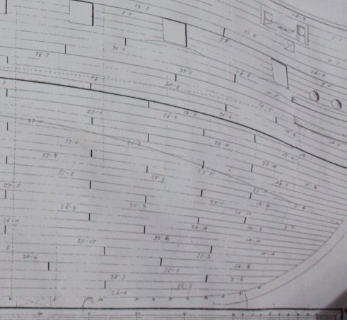
The garboard ends at the forward end of the boxing joint on the below expansion drawing as well as other planking expansion drawings on the RMG Collections site. I have not found any showing it ending elsewhere, but they may exist. Allan
-
Size of Rope and Serving for Stropping blocks
allanyed replied to Peter6172's topic in Masting, rigging and sails
Hi Peter What size guns are you working with? There is a chart of breeching line sizes from 1723 to 1765 on page 385 of Volume 2 of Caruana's The History of English Ordnance. The circumference varied over the years, but the closest to Endeavour is for 1765 and beyond. Caruana gives the following which he got from the Public Record Office: 32 pounder 7" 18 pounder 5.5" 9 pounder 4.5" From the Mariner's Mirror volume 18 4 pounder 3.5" From Lavery's Arming and Fitting page 141 for the gun tackle, the ropes were 3" for 24 pounders and above and 2" for guns smaller than 24 pounders. The text shows these to be diameters, but I believe this is a mistake as that would make the running tackle larger than the breech rope!! He does give similar CIRCUMFERENCES for the breechings to Caruana's figures. Allan -
At 1:8 scale you should have no problem doing the splicing although it will take a lot of time. When it comes to ship modeling, quick build is an oxymoron if ever there was one.
-
If you decide to use copper sheathing you might want to study Yve's Bellona build as it is possibly the only coppering on the various build logs that looks somewhat realistic although they should overlap but don't. The plates are to scale and there are SMALL nail dents instead of what look like giant rivets seen on other build logs. modelshipworld.com/topic/29729-hms-bellona-by-yves-vidal-caf-model-148/page/6/ Allan
-
Absolutely lovely work David. One thing, hope you don't mind, but the Admiralty only allowed the names on the stern between about 1770 and and 1780. As Diana was launched in 1794, she would not have had her name on the stern. Allan
-
Hi Daniel Your model is taking shape and looking quite nice! Are the cannon from the kit? The reason I ask is that they look like a cross breed of the Armstrong and Blomefield guns from the 18th century rather than the bronze cannon from 200 years earlier. Looking at the OcCre kit of the HMS Diana 1794, it appears they use the same hybrid cannon in that kit. Allan
-
Treasure Galleon La Nuestra Señora de Atocha, 1620
allanyed replied to davos522's topic in Nautical/Naval History
She is indeed a beautiful piece! I was of the understanding that she carried 24 to 28 cannon and the model shows only 8. The Fisher team recovered 20 bronze cannon but I am not 100% sure they are all from the the Nuestra Senora. Maybe time to take a ride to the Mel Fisher Museum in Key West for more details. The model looks like a modern day piece so I wonder when the model was built, and on what design/information it is based? Allan
