
Supplies of the Ship Modeler's Handbook are running out. Get your copy NOW before they are gone! Click on photo to order.
×


allanyed
-
Posts
8,149 -
Joined
-
Last visited
Content Type
Profiles
Forums
Gallery
Events
Everything posted by allanyed
-
 I cannot wait to dock in La Spezia in September and hopefully meet you in person and see this model up close and personal. I will PM you as we get closer to see if we can meet. Ciao Allan
 -
Bill's post just came up as I posted this. I am anxious to read responses on what to use as some aluminum alloys are very hard to weld. There seem to be some solutions on the 'net, but I hope someone here has done it with success and can share what they used and what they did. Dave, why not order a pack of brass or copper tubing and rods? Copper is easy to soft solder and clean up for blackening with liver of sulfur. Hope to see a new solution to add to my tool kit! Allan
-
I would go with files and/or chisels, but very slow and easy but hopefully some member has a full proof method to be sure every face is exactly the same and concentric.
-
Start with square stock the taper to each end them mark out edges of each face of the octagon then plane or chisel or otherwise remove the material until you have 8 faces that are concentric. I like to use a machined vee block for this kind of thing. If you do not have one you can make one of wood or find a local machine shop and ask them to machine one. The local shop owners years back did it in scrap aluminum bar they had laying around for donuts and coffee. Allan
-
Have fun, that is the number one priority!!!
-
Dave, There is a 25% difference in the diameter of 24 and 26 gage. The difference with 28 gage or 29 gage, which you also need for the eyebolts, and 24 gage would be 100% too large. The rings and eyebolts were made of materials of a size that was somewhat matched to the gun sizes. A long 32 pounder needed something more stout than a 9 pounder for example. If the LN had 3 and 4 pounders, for the rings the diameter of the material would be 1 inch with an inside diameter of the ring of 3 1/2 ". The eyebolts in the bulwark would be made of 3/4" diameter material with an inside diameter of 1.5". Just as an FYI, the rings for guns of 12 pounds and above used 1.5" diameter material and the ID ran from 4.5" to 6" These stats are from The Construction and Fitting of the British Man of War, p217, by Peter Goodwin and which he references the Shipbuilder's Repository of 1788. Again assuming 3 or 4 pounders in your case, for the rings, the diameter of the material would be 0.0152" so 26 gage is right for the rings. The ID is easily made correctly using appropriate size drill bits. In your case a 26 gage wire and a number a #54 drill bit for the rings and 28 or 29 gage wire and a #77 drill bit for the eye bolts. I would consider copper wire for both as it is easy to find, can be soft soldered, and easily blackened with diluted liver of sulfur even AFTER it is installed, without staining the wood or rigging. When I first saw these ring diameters I thought the ID was a bit small for the breeching rope. In researching a little further, Caruana shows the breech rope for 3 and 4 pounders at 3.5" circumference, so a little over 1 inch in diameter thus no problem securing to the rings. (The History of English Sea Ordnance, page 385) Hope this helps and was not too long winded. Allan
-
Also, a bit closer for you is the Musee National de la Marine in Paris. I understand it is temporarily closed to the public, but hopefully you can gain access as an independent researcher. I have not had the opportunity to visit yet so not sure what you will find as it has been closed for various reasons whenever we have been there or we ran out of time. We will likely be there next spring so I hope to see a report from you before then. 😀 Allan
-
kit review 1:65 HMS Endeavour - Artesania Latina
allanyed replied to James H's topic in REVIEWS: Model kits
Peter Many thanks for sharing your first hand honest observations. It will be interesting to see how the issues you have pointed out will be fixed. Allan -
Hi Sam and welcome to MSW. I assume you are in communications with the ship model curator at Preble Hall who I believe is currently Don Pruel. Their Rogers collection is stunning and on display to the public. If you are not already speaking with them, they may have what you are looking for. Allan
-
HMS Bounty by AdamA - 1:48
allanyed replied to AdamA's topic in - Build logs for subjects built 1751 - 1800
Loving your build and thank you for sharing! I know this is well in advance, but what plans are you going to use for the 23 foot launch which has become as famous as the Bounty itself? If you are not yet decided I did a detailed drawing of a 23 foot launch based on NMM drawings and scantlings from the plans as well as the scantlings in W.E. May's book on ships' boats that I can scale to 1:48 if you are interested. I look forward to your next progress post. Allan -
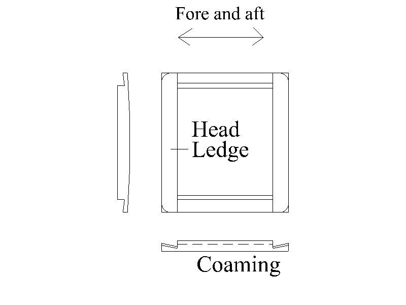
Regarding your timberheads, it may be easier to cut the openings in the cap rail before permanently gluing it in place as the timberheads come through the rail similar to how you show the timberheads in the beakhead bulkhead rail. One other thing for the future, the hatch coamings, the head ledges are cambered and rest on top of the coaming pieces, rather than the 45 degree joint. (Sketch below) These are seemingly little things that probably do not matter for some, but do matter for others. In the end, always your own choice as to what makes you happy. Cheers Allan
-
A lot of the things we do on our models are frustrating to say the least. You are a member of an extraordinarily large club when it comes to frustration😀. Regarding the tapering and shaping of the planking, have you studied the planking tutorials by Antscherl and the edge bending methods by Passaro? These apply even for boats, not just ships' hulls. Allan
-
Kevin, For the future, you might want to consider either softening the brass or using copper. Copper is softer and far easier to blacken with liver of sulfur than brass is with BW Casey or other blackening agents. Allan
- 129 replies
-
- 1
-

-
- Bounty Jolly Boat
- Artesania Latina
- (and 1 more)
-
Hi Gregory The name on the replica ship is above the stern lights instead of down on the counter. Has anyone ever seen the ship name above the lights on any contemporary drawings or models? This seems like a very basic practice for the short ten years the ships were mandated by the Admiralty to have their names on the stern. I realize there were a few exceptions regarding the years, but I have not seen exceptions on the allowable size of the lettering or location. Allan
-
Welcome Ian, Be careful what you wish for. You now have 42,000 well meaning advisors 😀 Build log??? DEFINITELY. As you are about to take a step in the build, look at multiple build logs first. Do overs are common for nearly all of us, but they are fewer if you can spend a few minutes to see what others have encountered. After you finish Bon Retour, you may want to consider the beginner through more advanced kits designed by David Antscherl at Model Shipways. These will teach you great techniques. David is a member here so you have a first hand helper if you have any problems along the way. Good luck Allan
-
Probably just a misspoken word as I see the carlings but the ledges are not shown. No need for either on a model if the deck is fully planked, but both ledges and carlings would be great to show if some deck planking is left off. Not a difficult thing to add the ledges from some scrap wood though, if they are not in the kit. Based on the scantlings in the Shipbuilder's Repository 1788, at 1:64 on the gun deck they would be 0.086" broad X 0.078 deep. For the upper deck they would be 0.0625" broad X 0.047" deep. The spacing of the ledges is such that there is no less than 9" nor more than 12" asunder. The breadth and depth are slightly larger on the upper deck in Steel's 1805 Elements and Practices of Naval Architecture. Looking like another super kit Christopher! Allan
-
That got a very loud LOL from me. Jim, Off gassing etc.....maybe valid points, maybe not so much, I have no clue. But, I don't think we will know the effects for a few hundred years based on the longevity so far of the contemporary models we see at Preble Hall, RMG. Paris, and on and on. If one of my models lasts half as long as these contemporary models, let the gas flow. Our great-great-great-grandkids can post here on MSW how our models are holding up to bees wax, CA, PVA, various types wood, etc. I only have 45 years evidence but so far, so good! Allan
-
Bluenose II copyright infringement lawsuit
allanyed replied to Nirvana's topic in Nautical/Naval History
Ron. $300? That would barely cover the cost of materials for a fully framed model of the Bluenose Someone got off cheap or did you miss a zero in there somewhere? 😀 Allan -
Anchor line size
allanyed replied to Dave_E's topic in Discussion for a Ship's Deck Furniture, Guns, boats and other Fittings
FWIW, for the circumference of the cables of the bower, best bower and sheet anchors, Lees gives a ratio of 0.62 the diameter of the mainmast. The kedge anchor was 0.060. Allan -
Most well made rope these days lack the fuzzies. Syren and a number of others make rope that essentially have no fuzziness to the naked eye. Waxing is really not needed in these cases. Some kits tend to include thread rather than rope and it can be very fuzzy. Rather than wax it, it might be a better idea to put it in the sewing basket for later use top mend a shirt or pair of pants and buy or make miniature rope for the model. Allan
-
Bikermark, Looking at Charter33's build log here at MSW the Caldercaft kit looks to be really good. The copper sheathing has giant rivets instead of small nails, otherwise she is a beauty so far. Looking forward to your build log. Allan
-
Modelling locks or Latches
allanyed replied to jackieofalltrades's topic in Metal Work, Soldering and Metal Fittings
Welcome to MSW Patrick! Do post an intro in the new member section about yourself and your areas of interest in shipmodeling. As you are a locksmith I imagine you have some great tales to share. Again, welcome aboard Allan -
Andrew, Many thanks for posting that extract from the plans. I had looked at drawing ZAZ6664 at RMG but it only shows the cross section of the coamings, thus missing these ports. I just now dug a little deeper and see ZAZ6665 that shows the ports. I scaled it and the coamings appear to be about 14" high so plenty of room to accommodate the small ports. Very interesting!!! Thanks again Allan
-
Aircraft plywood is available in most hobby stores and on line and is available in thicknesses down to 1/64". 1/32" thick material for example would be the equivalent of a 3" thick rail at scale 1:98. https://www.aircraftspruce.com/catalog/wppages/finnishbirch.php is one supplier, but I am sure there are more. You can make a copy of the plans and print on label paper then cut this out and stick it on the plywood. A sharp #11 blade on a scalpel or hobby handle can then be used to cut out the pattern. You may want to cut the outside first, then make a molding cutter from a piece of old hacksaw blade or stiff back razor and scrap a mold patten. Once done, cut the inside of the pattern. Alternatively you can make two or three patterns on the thinnest plywood and then glue them up with a little offset to form the molding pattern. Lot of ways to skin this particular cat. Allan
-
Thanks Trond!! I was curious about this as I was not sure if it was from a contemporary source or something modern and not applicable to the actual ship when she sailed in 1787. It is a very interesting item that I cannot find on any contemporary model or drawing so far that shows these ports. . Do you or does anyone following this build know if this was something contemporary? Thank you Allan