


allanyed
-
Posts
8,149 -
Joined
-
Last visited
Content Type
Profiles
Forums
Gallery
Events
Everything posted by allanyed
-
 Follow Druxey's advice in researching the books he mentions. The space between frames (an inch or two) precludes any possibility of the deck beams going between them. From Goodwin on page 66, the clamps were sometimes scored an inch deep where the beams rested. In addition the beam ends were sometimes wrapped with tar soaked flannel or paper, or had a notch scored about 2 inches deep to help prevent rot. These features will not be seen if the waterway is put in place, but something you may want to do for your own satisfaction. Allan
 -
rvchima, Maybe it was just a misuse of a word, but copper sheathing did not have rivets which would protrude, but rather 1/4" nails with 1/2" heads that would make dents into the sheathing. Yve's sheathing shows what look to be nails, not rivets and they are properly sized and spaced. I believe there would have been some nails inside the periphery of the edges, but still in all, this is one of very few model sheathing jobs on the build logs that is very well done. Allan
-
Le Soleil Royal by Nek0 - 1/72 - Marc Yeu
allanyed replied to Nek0's topic in - Build logs for subjects built 1501 - 1750
The VdV painting shows what look like pins but I can only see one line belayed to these. Also the painting is a Dutch ship, not French, so maybe no correlation to LSR in this particular case. I agree that the bowling pins on the model look like, well, bowling pins, not belaying pins. I wonder if they are originals or were they added at some later date? Is this the 1720 model at the Musee National de la Marine? While she is gorgeous in many ways, the rigging and painting look as if MAYBE she was renovated at some point. The belaying of the line to the cleat on the mast is rather odd for one example. Allan- 208 replies
-
- 5
-

-
- le soleil royal
- 104 guns
- (and 2 more)
-
Television broadcast regarding Endurance
allanyed replied to allanyed's topic in Nautical/Naval History
For anyone that missed this broadcast do look for a repeat. The entire modern expedition is fascinating and the collection of contemporary photos and movies made by the Endurance crew is awesome, including her last days as her rigging tumbled to the deck before sinking below the ice. Stories on how the crew survived, eventually eating the sled dogs to keep from starving, are heart rending. Allan- 1 reply
-
- 1
-
-
Congrats on your first build completion. Far and away better than most first time builds, mine included. One thing of note for the future, the knee of the head should be tapered to about 4" at the bobstay piece on the Swan class and similar size ships. Yours looks to be the same width (10"?) which would be the thickness where it meets the stem. I assume this is a design error from the kit manufacturer. Allan
- 164 replies
-
- 1
-
-
- fly
- Victory Models
- (and 4 more)
-
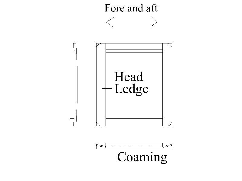
Looking good! One thing to consider for the future, the head ledges on the coamings sit on top of the coaming pieces rather than the other way around and are rounded versus flat. Out of curiosity, did the kit instruct the configuration you used? It would be a shame that they did not research properly to have this done correctly. Allan
-
Tom, The rigging changed in 1805, so are you looking for prior to the change or at the time of Trafalgar? MAYBE the rigging was not changed on Victory, but you have a choice. Lees explains in detail how the footropes, lifts and braces are rigged on the crossjack. He goes into detail on the slings and trusses as well including mentioning that chain slings could be used from 1793 if requested. Chain trusses came later, (1850) Allan
-
I second and third the above. What you show in the photos is indeed thread and ships did not use thread nor should a model ship. Miniature rope can be made by you or purchased from several sources and looks sooooo much better than thread. Allan
-
Kostas, I agree with you that you were better off to remove the stubs of the bulkheads. The moulded dimension of the top of the top timbers of the Victory is about 5.5" to 7" depending if at the waist, QD, or FC so about 0.06" (1.5mm) at your scale. I love that you are not trying to show treenails on the deck planking as they would have to be 0.008", nearly impossible to make and look good. Your gratings look far better than seen in the majority of other kit builds. Did you make these are they from the kit? It is hard to tell from the photos, but the openings would be about 0.03" (0.8mm) or less at your scale. These look to be maybe a little large, but hard to tell from the photos. Will you be following the planking tutorials here at MSW when you plank the hull? I look forward to your next progress posting. Allan
-
Daniel, You mention you could not find the plans on properly planking the hull. There are two that are excellent and can be found here at MSW in the Articles folder. https://thenrg.org/resources/Documents/articles/LiningOffYourHullPlankingTutorialAndFan.pdf and https://thenrg.org/resources/Documents/articles/APrimerOnPlanking.pdf Allan
-
Welcome to MSW Luke. I hope you enjoy your time here with your 40,000+ new friends. Allan
-
Brass Blackening Building Time Survey
allanyed replied to Dave_E's topic in Metal Work, Soldering and Metal Fittings
"Blacken It" was indeed the best in my experience. While I still use brass at times I have gone to copper whenever possible as it can be blackened in situ with liver of sulfur and I am very happy with 3D printed cannons in black resin as the detailing is often superior to turned cannon, especially at smaller scales. The only problem I have with the 3D parts is my own lack of skill in making the 3D drawings. Allan -
Just as an FYI I believe West India boxwood is from West Indies, not India so there is the same issue in shipping or worse as the Lumberyard gets it from their source then would have to transship to India. If possible it is better if Vinod finds a local wood supplier rather than one from the US. Allan
-
If you are trying for accurate, to-scale looking sails, you are better leaving them in the box. There has been a lot of very good information shared on sail making here at MSW using alternate materials such as silk span if realistic looking sails is a concern. The kit makers should be embarrassed by the sails they provide. Allan
-
Siggi, sorry for the confusion, I was complimenting your use of paper patterns. This is something other modelers should try if they have not done so already. Allan
-
Brass Blackening Building Time Survey
allanyed replied to Dave_E's topic in Metal Work, Soldering and Metal Fittings
Any concerns about time might be considered the antithesis of building a fine ship model 😀 This hobby or even avocation of ours is more like a crock pot than a microwave in getting things done. Allan- 16 replies
-
- 10
-
-
https://play.history.com/shows/historys-greatest-mysteries/season-3/episode-99 About the TV show airing 22 March in the US. Allan
- 1 reply
-
- 3
-
-

-
Gregory As the transoms were upwards of 3 to 4 feet broad and 2 to 3 feet high, it would not have been easy to make this from a single piece of wood. Planking on a ship's hull and transom were not tongue and grooved so is there a reason the transom on a boat would be done this way? If t&g were used in real life it would not be seen. Allan
-
Thanks B.E. I never thought to look in Lavery's book. What is a little odd is that the dimensions he gives for a 64 are a bit different than what is on the Dorsetshire drawings. I double checked the dimensions of the main body of the stove on the plans on the RMG site and using the top view they are 6' 10" fore and aft, and 6' 3" athwartships. Dorsetshire may be an anomaly or Lavery uses an average from various sources as he does not give a source for his chart that I could find. Either way, your stove is a beauty. Allan
- 857 replies
-
- 2
-
-
-
- Sphinx
- Vanguard Models
- (and 1 more)
-
Your stove is a beautiful piece! The Dorsetshire (64) 1767 stove looks to be redrawn from the contemporary drawing of the inboard profile and deck drawing so most likely a very accurate basis to use. https://www.rmg.co.uk/collections/objects/rmgc-object-81162 and https://www.rmg.co.uk/collections/objects/rmgc-object-81163 As Sphinx (20) 1775 was substantially smaller and had a much smaller crew of about 200 versus about 500 for a 64 like Dorsetshire, would the stove be just a smaller version or a different design in some ways? The stove on the Dorsetshire looks to be about 86" X 88" not including the tray on the forward side. Would this fit on the space available on Sphinx? Allan
- 857 replies
-
- 2
-
-
- Sphinx
- Vanguard Models
- (and 1 more)
-
Looking good David, and kudos for doing your research with the sources you listed! One small note for consideration if you are going to have the deck exposed to show the beams, etc. on other decks and/or future builds. Your beams, carlings, and ledges (what I think you are calling athwartships carlings) look spot on dimensionally, but hard to tell from the photo. Regarding a first rate like Victory, for the lower gun deck the beams at midships were 18" square, the carlings 11.5" broad by 10.5" deep, and the ledges 6" broad by 5" deep based on the scantlings from Steel's Elements and Practice of Naval Architecture and The Shipbuilder's Repository and shown in the Scantlings of Royal Navy Ships as well. The spacing of the ledges would be such that they would be "in the clear asunder not more than 12" nor less than 9" so maybe fewer than what you show. For the middle and upper gun decks, the scantlings of the beams, carlings and ledges are of course slightly smaller as would the scantlings be different for lower rate ships. Looking forward to your next progress photos. Allan
-
AJ The idea of air scuttles may very well be the answer, but then I wonder why they would have the plants below deck with virtually no light. Up on deck could be tough though in rough weather with salt spray on the plants although bread fruit plants are tolerant of salt spray for short periods. Interesting stuff that comes out of the builds here at MSW! Allan
-
Ras, Thank you for sharing your research on this project. I find it fascinating and look forward to your build. Allan
-
My day was going really well, and now it is over the top in good news. Allan