


allanyed
-
Posts
8,149 -
Joined
-
Last visited
Content Type
Profiles
Forums
Gallery
Events
Everything posted by allanyed
-

Forming a garboard
allanyed replied to rudybob's topic in Building, Framing, Planking and plating a ships hull and deck
THAT was funny Gregory!! -
Forming a garboard
allanyed replied to rudybob's topic in Building, Framing, Planking and plating a ships hull and deck
Spiling (with one "l") 😀 is a great way to go per Gregory's post. There is a very good tutorial on this here at MSW. https://thenrg.org/resources/Documents/articles/APrimerOnPlanking.pdf Allan -
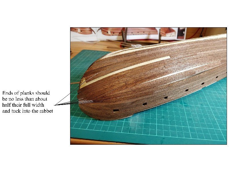
Peter Have you studied the planking tutorials? There appears to be no taper to the planks you have installed so you will run out of the space needed to land them at the rabbet where they should be. If the planks are not tapered properly you will wind up with this, which no shipwright would have ever considered.
- 79 replies
-
- 1
-

-
- Endeavour
- Artesania Latina
- (and 1 more)
-
Eberhard I agree that it seems like the kit makers do indeed follow the old protocols as you describe rather than doing any research into contemporary practices. Three of the worst offenders to me include the belaying pins on ships that would not have had any or if they do belong are the size of bowling pins , gratings that look like dividers in a card board box, and copper sheathing with giant rivet heads instead of small nails. Allan
-
Touché Roger!!! My first book was from Davis followed by Longridge (quite a leap, I know) I no longer have the Davis book by I remember it inspired me to get my tool collection started including my first table saw and planer and start building model ships. I guess I can say his book cost me a fortune over the years, but it also led me to thousands of hours of pleasure in my little shop space which has value far beyond money. Allan
-
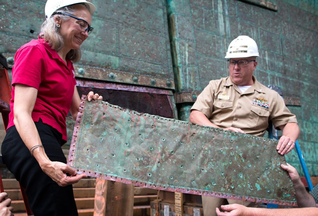
Hi Sonny Thanks for that lead for the videos. I did some searching and found his episode 60 on HMS Victory which has him making the sheathing. I cannot speak for the rest of his videos, but this particular episode really is a disservice to those trying to research how the coppering really looked. He makes the incorrect huge pimples like most kit plates have rather than tiny dents which would have been correct. Cheers Allan
-
To which parts are you specifically referring? Allan
-
Welcome aboard Grey. Hope to see you get started on a project. Never hesitate to ask questions. Most answers are probably already somewhere in the posts here at MSW as well in any number of books that you can research on your own, but there is always something new that comes up that has not been covered. , but you now have 40,000 new teachers to share their skills and experience. Are you going to start with a kit or scratch build from plans? Before spending any money, you might want to post a question to get opinions on something specific you have found to be of interest. There are some excellent kits as well as some that are not very well researched or produced, so beware. Allan
-
Simple yet effective!!! Great post on how you did this. Thanks Allan
-
Hi Frank, Good for you making your own sails! Maybe something to consider for the future if too late for this project...... the thread count of muslin is typically about 150 per inch compared to cloth that would be to scale which would be closer to 1200 to 1500 per inch which is hard to come by. The tissue paper, like silkspan is actually better to use than any cloth at your scale. There are a number of posts here at MSW and the $8 sailing making booklet by David Antscherl that will help you yield realistic sails which is impossible with cloth and sewing at 1:60. Allan
- 510 replies
-
- 1
-
-
- reale de france
- corel
- (and 1 more)
-
Very nice Peter (except maybe the screen shot of SOS, on your computer screen instead of MSW.🤐)
- 79 replies
-
- 1
-
-
- Endeavour
- Artesania Latina
- (and 1 more)
-
Forming a garboard
allanyed replied to rudybob's topic in Building, Framing, Planking and plating a ships hull and deck
Looks good! Even with this small craft, don't forget to layout strake marks on the frames to get the proper taper on the planking above the garboard. Allan -
I agree with your own comment that it is a poor excuse. 😀 While your model is pretty, looking at your photos there is very little in the details that resembles a real ship which is typical of DeAgostini kits. In the end if you like it that is what is most important.
- 69 replies
-
- 1
-
-
- soleil royal
- deagostini
- (and 1 more)
-
Help with 5mm deadeyes on Bounty
allanyed replied to JayDee24ca's topic in Masting, rigging and sails
JD Does the kit provide the metal rod material to do this? There are usually three pr four pieces to this on the fore and main mast shroud deadeyes, the eye around the deadeye and into the slot on the channel then one or two chain links going to the hull and a lower plate. There were no lower plates on 17th century vessels and there are not always plates on the mizen mast shroud deadeyes. You can see a model of Bounty on the RMG site to see what is appropriate as I would not trust your kit instructions without doing some research first. https://www.rmg.co.uk/collections/objects/rmgc-object-68763 Have you looked at the various build logs including other than Bounty? Do a search on deadeye chains here at MSW, there are pictures and discussions on various methods members of used. Allan -
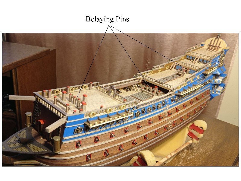
Grandpa, See picture below. Soleil Royal would not have had belaying pins. I am sure this is not your mistake, but rather the kit maker. DeAgostini must not have done very much research to produce such a big mistake. Allan
- 69 replies
-
- 4
-
-
- soleil royal
- deagostini
- (and 1 more)
-
Fabulous as always! I have never seen the lanyards to help open the shutters by the lights, but it makes a lot of sense. Is this something you have seen before? Thanks Allan
-
Artesenia Latina Printed Instructions Needed
allanyed replied to Aj73's topic in Modeling tools and Workshop Equipment
I went to the address above and it comes up to their home page. They claim they do not offer printed plans of "old" kits. Maybe better to email them under "contact" at the bottom of the home page where they have a mention of further contact for old plans. If it is a new kit tell them your kit came without any plans on paper or CD or go to where you bought it and get a replacement kit that has the plans in the box, be it CD or paper. Just curious, is your father a beginner or very experienced builder? Allan -
https://artesanialatina.net/en/contact/contact
-
https://artesanialatina.net/en/contact/contact
-
Hi Jonathan, Regarding the pins, I assumed this was a kit thing as Mantua is not well regarded for doing a lot of research before designing their kits. I look forward to your build log on Victory. Having a copy of Longridge's Anatomy of Nelson's Ships will be a great help as well as the Caldercraft Victory build log here on MSW by Robert29. Allan
-
Nirvana, Depending on the temperature and size that you want, the clay baking ovens may be a good thing for you. The one I have from Amaco goes to 300 degrees F and has a timer for up to 30 minutes. Allan
-
Thanks for this information Eberhard, it makes for a very good day for me learning something new first thing in the morning! 😀 Is the below from the Constitution what your are referring to color wise? Allan
-
Ain't that the truth!
-
As many folks have advised above this really is a personal choice for you to make, but it should take into consideration cost, time, and space. Regarding space, UV protection needs to be considered in some form so may affect where the model will be displayed. Allan
-
Your attempt is superior to the vast majority seen on build logs here at MSW. You show dimples instead of pimples which is realistic, albeit a bit larger on the inside ones than the peripheral rows. Those indentations on the edges look much closer to scale of using 1/4" nails with 1/2" flat heads. And, unlike the vast majority of copper sheathing on models we see here, your plates overlap as they should be. Kudos to you for this. There is a tutorial by Gene Bodnar at NRG that is not bad, but uses copper tape, not brass. I don't know if it really is copper or painted as was yours. https://thenrg.org/resources/Documents/articles/CopperSheathingaHull.pdf On the actual ships the coppering was no doubt green in short order and there are some nicely sheathed models with the plates painted an oxidized copper green as an alternative route you might want to consider. Allan