allanyed
-
Posts
8,149 -
Joined
-
Last visited
Content Type
Profiles
Forums
Gallery
Events
Everything posted by allanyed
-
 Thanks Eberhard, I appreciate you following this build and sharing your experiences now and over these past years. I guess if you get to the UK, steak and kidney pie will not by your first choice. 😄 I love snails as well, but my wife went from loving them to hating them when we lived in Southern California many years ago and she saw them always crawling on the side of the house and getting into the succulent plants for their own meals. Allan
 -
Ernestina Morrissey by Jond - FINISHED - 1:48
allanyed replied to Jond's topic in - Build logs for subjects built 1851 - 1900
I give you a TON of credit for having the patience to rebuild rather than try to fix/juryrig/coverup. She is looking really fine!!! Allan -
Valeriy The shackles are terrific! Are you making the flanges separately and soldering the to the ends of the half round rods or flattening the ends then filing them to shape or some other method? Thanks for sharing!! Allan
-
Wefalck, when you give this sail making a try as you described, PLEASE post a "How To" along with photos here at MSW. As far as getting not being able to get the paper in Paris, based on my visits to your city over the years, I would very quickly give up the paper in exchange for a good bagette and jambon for lunch and a plate of rognan avec moutard for dinner!! Allan
-
Roger, I have gone the exact route that you describe. I did indeed do some testing to check if much tension would break or distort the finished rings. Holly being the choice I made turned out to be a good one as they held up to my makeshift tests with no issues at all. If this were to be a pond model, I would likely have gone with something stronger. As it is static and the sails will be my first go at using silk span since I built a few planes WAAAAYYYYY back in time, they will be quite light and should present no issues. I have read and re-read David Antscherl's booklet on making silk span sails and will post my results once I begin making them. Got the materials he listed so ready to go in the near future. Wefalck, I was able to get the scale size wires I was looking for from my go-to supplier, McMaster Carr. The hardest part was they had so many wire choices that I had to spend a lot of time to be sure I made the right selection. Your comment on wheel chairs on a sail boat is well taken. The boat is designed for leisure day sailing, but of course any wind can cause her to heel over, so I am positive it is something the designer and builders have considered. Their yard is busy as can be right now getting Ernestina back to sailing condition which will be a treat to see when she is back in the water. Allan
-
Keith, I had never used styrene in the past as it is non-traditional and I TRY (although do not always succeed) to stay with traditional contemporary materials whenever possible, ie. wood and metal. Regarding boring out a rod, I should get a cutting tool and give it a try as it has been so long since doing it and there are times when it would be more accurate than a drill bitt. I am pretty sure it should be nothing more than the right size/shaped cutting tool and setting up the tool holder properly but would love to hear and see anything you can offer to avoid mistakes. Thanks for the offer!!! Allan
-
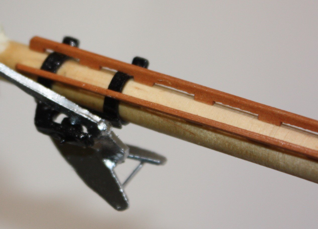
Keith, Wood is what is proposed on the actual vessel so I thought to give it a try. That and the fact that I could not machine a hole 0.65" diameter in brass stock. I don't have the skill to do that nor a drill bitt that large to do so on the lathe. If it had been 1/2" or less I could have drilled a hole in a piece of brass stock and then cut the rings. IF the wood does not work out I will bite the bullet and see what I can do to to get a proper sized drill bitt or learn how to machine the hole with a cutting tool. I remember doing this in a shop class back in the 60's on a full size lathe aboard ship, but over 50 years later, memory is not serving as well as it once did. :>( Regarding the anchor, I did a search on line to see how these types of anchors were assembled and found a few drawings as well. I made the arm in two pieces as there is a pivot, then made the flukes separately. I made all pieces from styrene, then silver paint to represent the galvanized finish on the anchor. The ring on the end of the arm is just a piece of brass rod. Not overly complicated. I had never used styrene in the past but after following Garry's Stonington Dragger build log thought to give it a try and found that there are definitely items that warrant use of this material. Allan
-
Made the plough anchor and anchor roller which is attached to the bow sprit. Also making hoops for the main and fore sails to go on the masts. I have made them of brass and colored them in the past, but trying wood this go around. I have soaked strips of holly that were cut to the proper width and thickness then wrapped them around a dowel slight larger than the widest diameter of the masts. Once dry they will be cut slightly oversized, taken off the dowel and glued to form the hoop. So far, looking good but the jury is still out on this one. Holly is extremely easy to bend without splitting when wet so I have high hopes on this. Allan
-
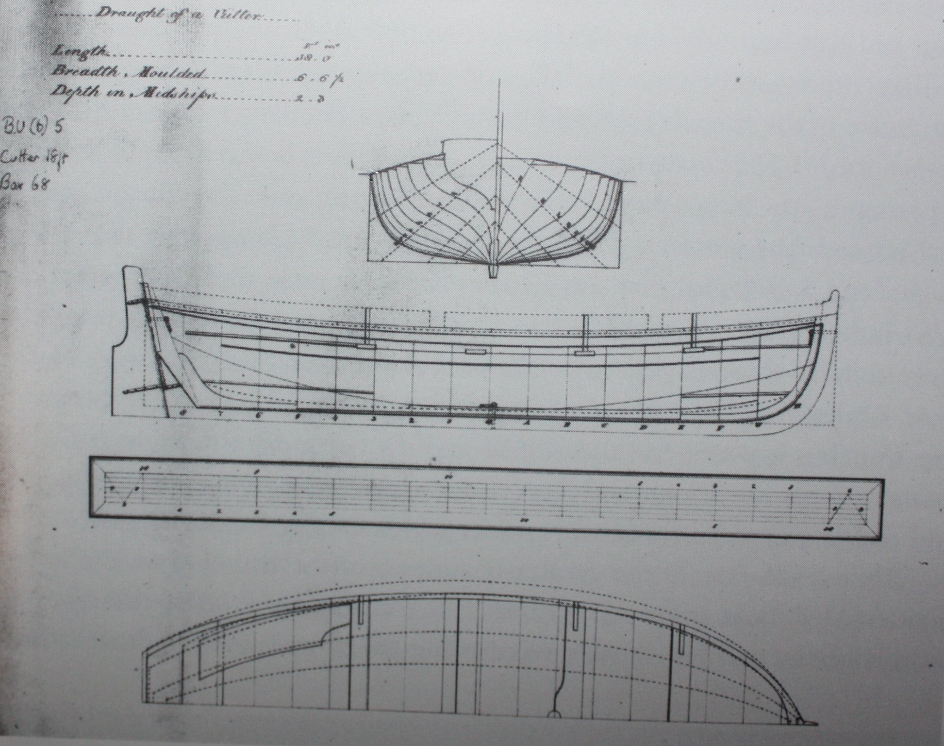
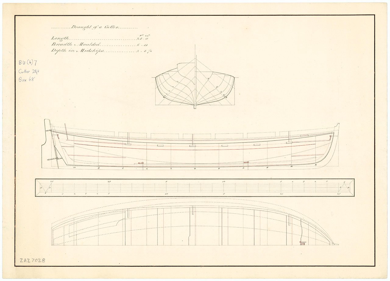
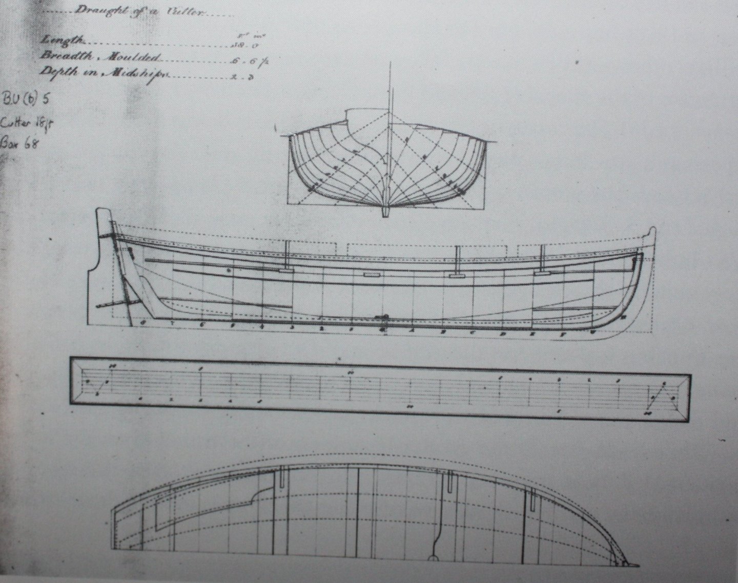
Pete, perhaps the below contemporary drawings will help. Note that these cutters have no ears, but many of the other items mentioned previously, plus the floorboards. (Sorry, not sure of the proper term on this one.) Also note that the first drawing shows six cutout for the oars, but there are actually three per side unless it is double banked. As it is between 6 and 7 feet in breadth, I am pretty sure it would be single banked. If you need scantlings, feel free to PM me. Allan
-
Hi Pete Assuming it is wood I have never had any problems building cutters and other lapstrake craft using carpenter's glue. These include 18 foot long boats which are right at four inches long with planks only 0.02" thick at 1:48 scale. I do like to use holly for the planking as I have never had a plank split or break but will be OK with any wood. I looked at pictures of your boat on their website and the finished boat does look nice, but I would be concerned that the drawings and photo of the finished model are missing a lot of items found on most cutters. This include such things as the thwart with a cut out for the mast, the ears, chocks, and breast hook to name a few. There are what appears to be places for three oars per side, but they look to be aligned rather than offset so every other thwart has no place for an oarsman to place his oar. On all the contemporary drawings I have seen (there are a lot of them available for free at the NMM Collections site and Wikimedia) there is also a cross thwart at the transom for the helmsman which is not shown in their pictures. Some of these items may or may not have been present depending on the year, but in Mays' book on ship's boats he gives scantlings for all of these items for cutters of various lengths, so some or perhaps all of these missing items likely should be present. Perhaps their plans are more detailed and show these parts. Allan
-
For long guns, assuming the Falconer drawing is accurate, it looks as if the recoil is closer to 4 feet plus/minus. According to Caruana in volume II the History of English Sea Ordinance, for a nine foot 32 pounder for example, in the Regulation of 1723 the breeching line was 6" in circumference and 30' long. In the updated Regulation of 1747 the circumference was 7.5", then reduced to 7" in 1765. He could not find circumferences for later years but comments that with the introduction of cylindrical powder about 1800 and the resultant more bang for the buck, the circumference of the breechings may have increased yet again. The length remained the same, 30 feet for 32 and 42 pounders. The length of the breeching for 9 to 18 pounders was 28 feet and 27 feet for smaller caliber guns. This seems it would allow more closer to 4 or more feet of recoil. Allan
-
Keith, I usually make my molding scrapers by chucking the grinding wheel in the lathe then hand hold the stiff back razor on the tool holder to grind the grooves in the blade. It appears you have the grinding wheel chucked in a drill press and have the blade in a vice. I can see this being much easier to control and safer assuming the vice is on an X-Y table/movement set up. Is this the case in your set up? I am going to go this route in the future for the precise control and safety it offers. Allan
-
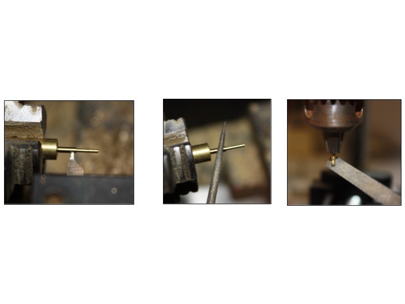
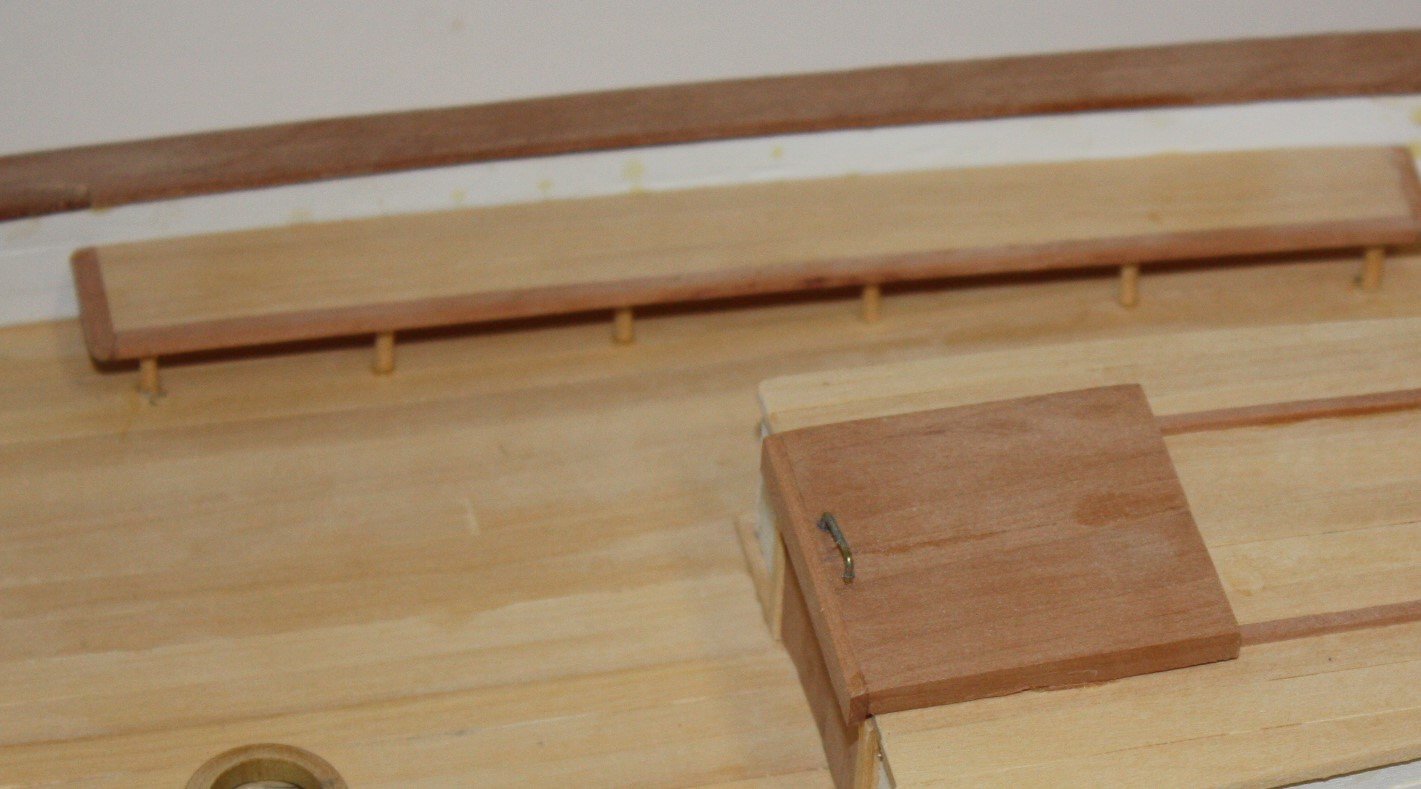
Pat, Keith, and Kurt, MANY thanks!!! I did receive the stainless steel wire and crimp pieces for the larger diameter wire and will be doing some experimenting in the near future. I also will be going to Michaels for supplies setting up sail making stretcher board frame and such as explained in the sail making booklet by David Antscherl so will get some beading wire to see how it compares if they have appropriate sizes. Even if they just have the crimp pieces it will be worth the trip into town. I have an electricians' cutting/crimping plier but will look at the crimping tool as well. As you say Pat, some experimenting into this new venture is no doubt appropriate so will be doing just that and will post the results here. Thanks again gentlemen. Couple updated photos. Deck cleats have been made and "bolted" to the deck. Each cleat was drilled and has a brass rod epoxied in place. A hole was drilled in the deck for each cleat and the cleat then set in place with the rod passing through the deck and epoxied in place. Small fife rails were installed as well. The pins are brass and were made on my lathe and the mini drill press was used to file and sand the end of the handle portion. They were then cleaned with acetone and blackened. The first two coats of clear finish have been applied. A light steel wool rub is needed in a few places and some touch up spots for sure, then the last coats of finish will go on. Allan
-
Henry, for the sprit shroud deadeyes you make a great point and Lees does point out that the lashing should lie on top of the sprit and one leg would indeed be shorter than the other. But there also some deadeyes at the top of the sprit for the stays, and some underneath for the bobstays and these did not usually have eyes that were lashed together, but rather were spliced together. Not an easy task on a model though!! Lees comments that after 1773, hearts were used in preference to deadeyes for the sprit shrouds which would be appropriate for Constitution, IF she was rigged similarly to the British. Same goes for the forestay and preventer stay. Allan
-
Bob, pages 49-50 of Lees' Masting and Rigging give great detail on the various deadeyes including outer bobstay, fore stay , fore preventer stay, sprit shrouds and so forth. For the time period of the Constitution, assuming she was rigged similarly to the British vessels, each deadeye would have a collar which was always spliced at the outer most point of the groove of the deadeye. The collar would be served for it's entire length. Often the collars were covered with leather as well. There were wooden cleats, usually four or more, attached to the sprit for each collar to prevent them from sliding along the sprit. Lees also addresses the order of dressing the collars and deadeyes of the bowsprit for each time period covered in the book on page 158. Allan
-
Welcome Doxi Just saw your post and when I saw you are from NE Ohio it brought back a lot of great memories of time spent on Pymatuning Reservoir catching bass, lots of walleye and the occasional muskie about the time you were working on the Constitution. Allan
-
Odds Should you need additional details, if you do not already have it, get a copy of Chapelle's American Fishing Schooners 1825-1935. As the Gertrude Thebaud was built in 1930, the book has a lot of appropriate details from fittings to rigging. I love/hate this book. I love the details and use it extensively when building a schooner model. I hate the fact that the index only gives boat names, nothing on specific items. It takes a bit of hunting through the book at times, but it is definitely the best source of period information for the schooners such as your build that I have seen. Allan
-
Hej Jean-Philippe, Please do consider making your own. David Antscherl has written a VERY detailed piece on how to make sails from silk span and based on his work over the years, I am going to be using this in my upcoming sail making adventure. It is a supplemental booklet that comes with Volume IV of The Fully Framed Model. I will be posting on this in the next month or two so you will be hearing from a newbie when using this method. Allan
-
Thanks Roger!! Yes, real time. I have been under a bit of a self- imposed deadline and trying to give at least 5-6 hours a day on her, often more. BUT, I do NOT get any pressure from the client at all and it has been a great joy building a model of a vessel that is literally still on the drawing boards. There are two items that I have found in building the model that indicate some adjustments are needed on the drawings and they have welcomed these pieces of input. Back to making sawdust. Allan
-
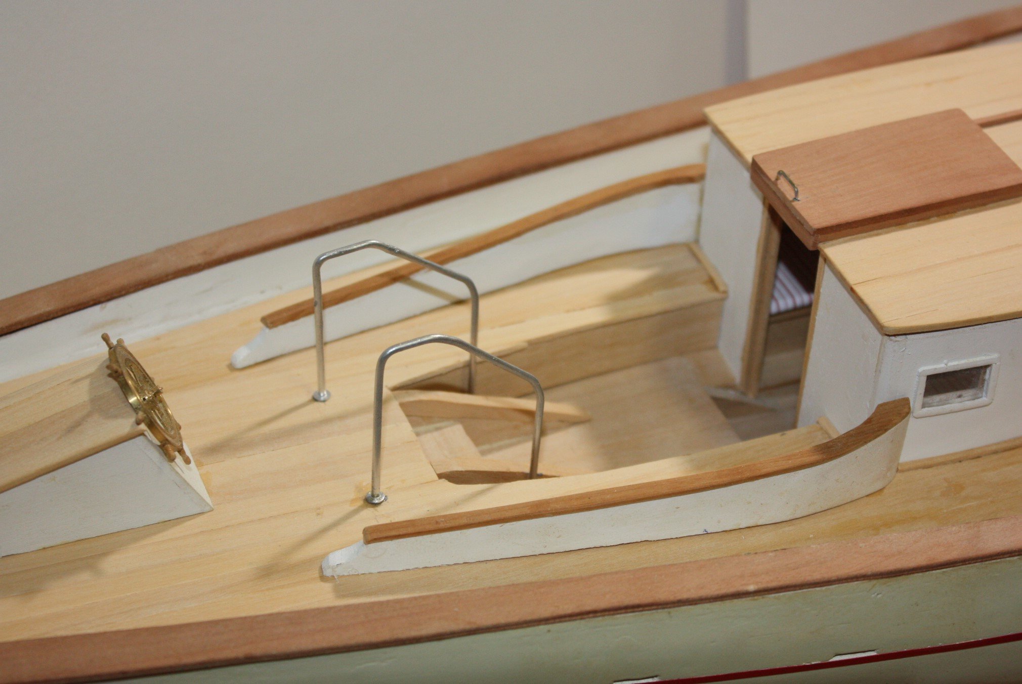
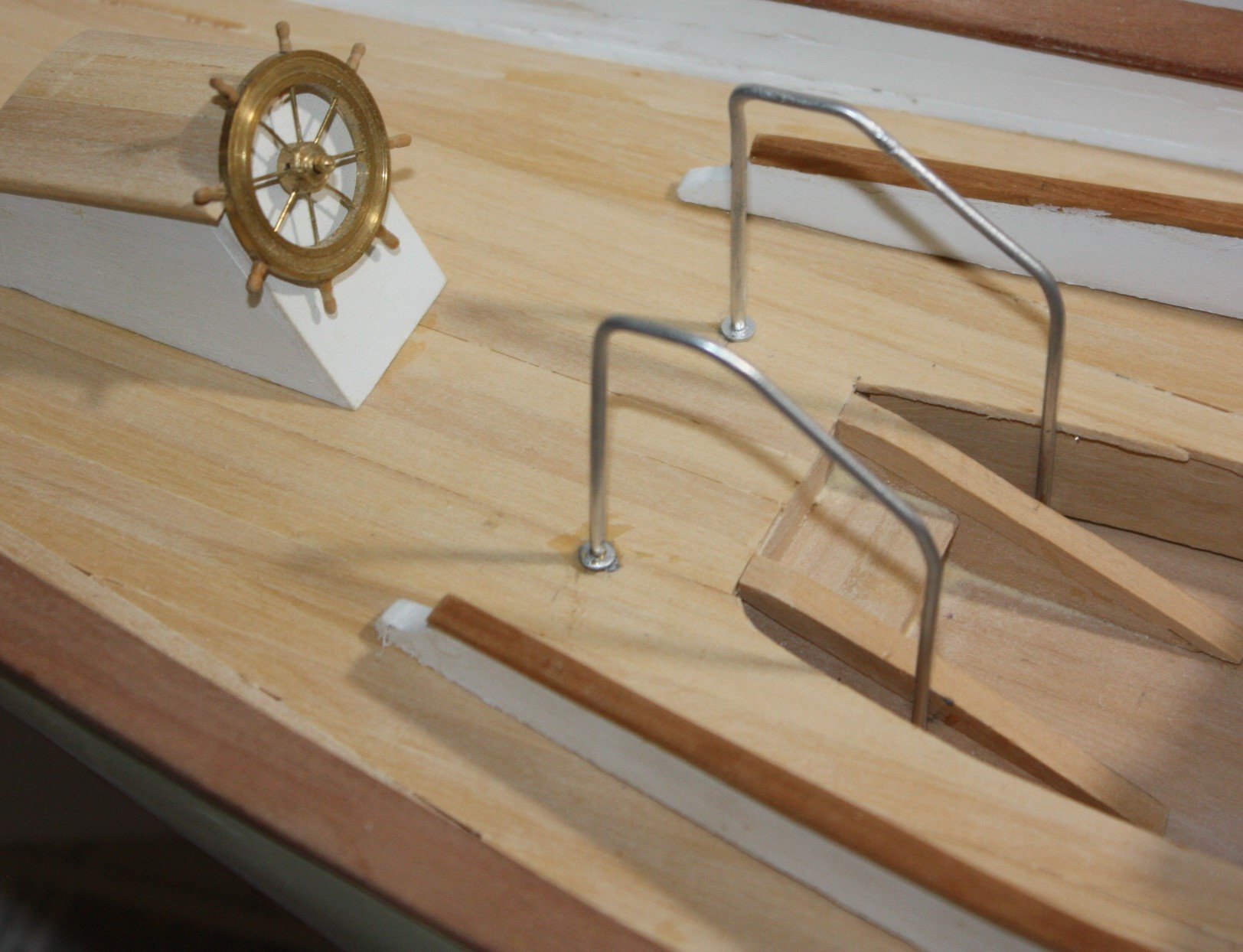
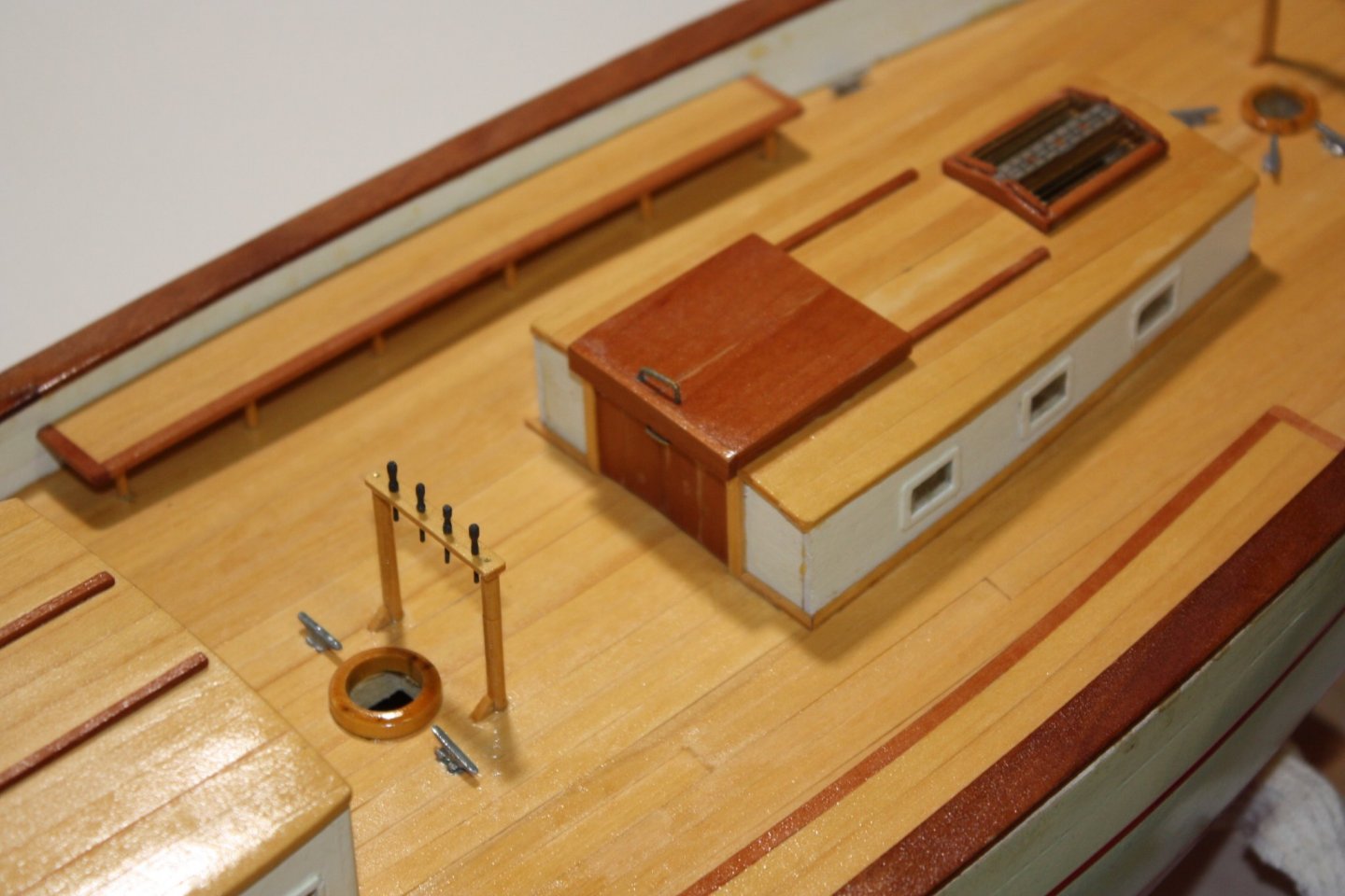
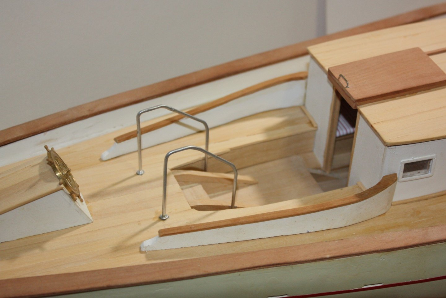
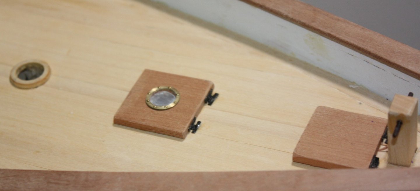
Thanks to all of you! Thanks Pat, but I did not show the skylight in the photos as it is a mess IMHO. The photos do show the sliding tops at the entrance to the deck houses, but I left out the skylight for now. The problem was in making the hinges. The frame and protection bars were not an issue, but the hinges are really small even at this scale and have been a challenge. Couple ideas have come to mind that I will be trying today and tomorrow. Gary, I agree on the colors and was very happy that the architect had done the color drawing as well as the architectural drafts. To try to match it reasonably close I have, Castello for the decks and house tops, cherry for the rails, Swiss pear for the doors, hatches, and other red trim pieces, and English boxwood for the mast rings as it machines so nicely. Metal parts are all brass, most of which are blackened, frames are birch plywood, and deck frames and all parts painted white are made with poplar from the local Home Depot. Glad I have maintained a scrap pile over the years as it came in handy for this project. I last bought cherry about 10 years ago, and feel good now that I kept all the odds and ends that I feared would never see the light of day again. If anyone has good experience rigging wire shrouds and stays, I would love to read any advice you can offer. This will be my first foray into using stainless steel wire for the standing rigging. I have two sizes of 7X7 strand SS wire on order from McMaster Carr as they had a good selection of sizes to match scale sizes for the model and their prices are fair. Looks like I will have to make my own compression clamp fittings and not sure of the best way to make these. So far I could not find any that were small enough to go with the wire sizes I will be using. I was able to find down to 1/16" but that is the equivalent of 1.5" diameter rope which is too large in this case. Allan
-
The deck is planked and the deck furniture in place. The skylights on the forward cabin area (which is set up as a classroom for twenty students) did not come out as I wished so will be a do-over. The top of the aft cabin can be removed to view the inside area and worked out as I had hoped. For finishing the deck planks I mostly used a scraper to remove high spots then sand paper finish and still find this preferable to any other methods I have tried in the past. I know this is common methodology, but for those who have not tried it, it is worth a go. Stiff backed razors or even a chisel can be used as a scraper if there is not a scraper already in the shop. Note there are side benches midships that seat 8 per side as well as the bench area going down into the aft cabin. The back rests in this aft seating area are sitting loosely at this point but will give an idea on their shape. These took a bit of doing as I had to start with a block of wood and cut, carve and sand to get the shape required. There was no way to bend these as they are quite thick at the forward area where they make a 90 degree bend. Not sure I like the design of these rests, but they do match the drawings. There is a bit of clean up with a scraper and sand paper, but nothing major, mostly finger prints/dirt/pencil reference marks/small glue spots which will definitely show once a clear coat finish is put down. Photos really help spot otherwise unnoticed items to clean up and other faux pax. After the final cleaning up should she should be ready to start masts, booms, sails and rigging. Going to give my first try using silk span and have been studying the supplement in Volume IV of TFFM on making sails with silk span. I had always used maximum thread count cloth in the past, but want to see how well this method compares. Allan

-
Just posting a "Like" is not enough Gary. Following your build has been a great ride!!! You have given a lot of good information for future use by many members and it is greatly appreciated. Allan
-
Shipman, talking to the void for years? Yeah, it happens to most of us. Love the beard man. Bet you are getting busier as Christmas approaches!! Allan
-
what is the best hand plank crimper
allanyed replied to ronald305's topic in Modeling tools and Workshop Equipment
Ronald, Regarding the TIGHT turn on the plank in your last photo, David Antscherl addresses this in detail in Volume II of The Fully Framed Model. He also goes into detail of bending using the Kammerlander method of using a heating iron against wetted wood while it is held in the place where it needs to be bent to shape in Volume I. Specifically regarding that crazy tight turn area, it is common to have a triangular gap between the last "straight" strake and the curved strake. This would be filled with a field fitted piece of wood. Allan -
Byrnes Table Saw making a 1mm by 1mm strip
allanyed replied to CharlieZardoz's topic in Modeling tools and Workshop Equipment
Mark, Don't throw away the bamboo chopsticks. Split them several times, stick them in a plastic bag, and they are ready for the drawplate to make trennals the next time you need some. Allan