allanyed
-
Posts
8,133 -
Joined
-
Last visited
Content Type
Profiles
Forums
Gallery
Events
Everything posted by allanyed
-
 Dan, Fully rigged, oh my. I look forward to many months (years) of following your build. Maybe it will give me the spark I need to go back to rigging something more complex than a schooner. Keep up the great work. Allan
 -
Frame faces
allanyed replied to SaturnV's topic in Building, Framing, Planking and plating a ships hull and deck
Richard, Yes they should lie flat on the table unless the futtocks are stepped or tapered in width as they rise. Even so they would probably be "flat" on one side. Allan -
Druxey hit the nail on the head. Scratch or kit. If kits, far fewer tools are needed. They are all desirable but less of a necessity. If scratch, have you considered your library as well as your tool cabinet? Steel, Lavery, Lees and recent publications from Sea Watch books by members of this site that will help you in your endeavors. Allan
-
Loblolly Couple points to consider: English walnut has been around for centuries as have ship models. I don't recall ever seeing or reading about walnut being used on the old models. Same for models in France or other parts of the old world. Walnut being rather large trees when mature certainly makes it easier to cut down to modeling size lumber than boxwood for example, yet boxwood is commonly found on contemporary ship models. I suspect it may partially be because walnut is not the greatest wood for ship modeling. My own experience with English walnut is not good but better using American (Black) walnut. It does not fray or splinter like English walnut and seems to be harder than English walnut in that it does hold a nice sharp edge. Walnut sawdust stinks and is a respiratory irritant as well as a skin toxin. I no longer use walnut for these reasons (but I do like to eat nuts from the English walnut better than from black walnut trees.) For me, it is better to use box, castello, some fruit woods such as apple and pear, or a host of other hardwoods. Allan
-
Sad, of course it is. But think about it. In 100 years people will look at these phones and shake their heads in amazement at how people had to use a hard device to communicate rather than telepathy or whatever they will be using by then. It will be as interesting to them as ship models are to us. That said, ship models are by far more beautiful and the intricate details that we see were made lovingly by hand, not robotic arms. Allan
-
Frame faces
allanyed replied to SaturnV's topic in Building, Framing, Planking and plating a ships hull and deck
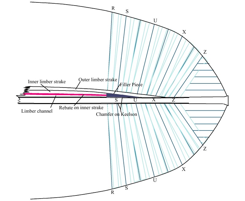
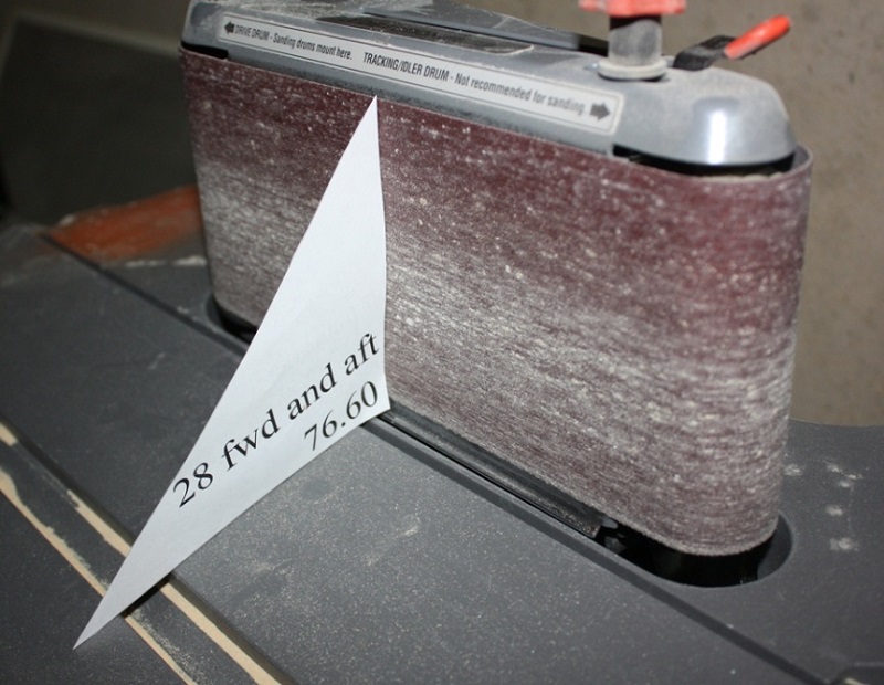
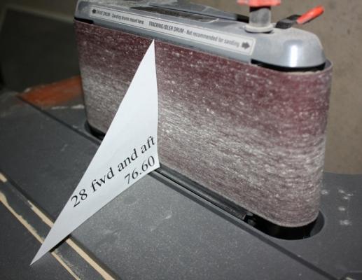
Richard, Russ has given good advice. The cant frames indeed lie at an angle, and each cant frame lies at a different angle. They are beveled inboard and outboard to allow the planking to fay completely against the frames as it bends around. These are the most challenging frames to make and to set in place. I usually make a set of card stock templates, one for each angle, then use these to set the table of my sander before sanding the part of the frame that is secured to the deadwood. This assures that the angle on the frame is correct. To chisel or sand the angle by hand is not easy to be as accurate. In the photo it is marked 28 forward and aft which are the two frames at station 28 which was at the aft deadwood. Allan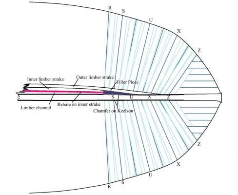
-
Richard, Yes Allan
-
Bluto, You have asked for a whole lot of information that by rights takes pages to explain. There are thorough explanations in Ed Tosti's book on Naiad as well as Volume II of Euryalus (36) 1803. These are available from Seawatch Books. You can also get some insight from Ed's really fine build log on the Naiad here at MSWorld. Allan
-
If you are painting, oak is probably OK. If it is to be left natural, it is quite grainy and does not look quite right. I am not a fan of walnut for anything except that I have used it for wales on occasion and that was American black walnut. My preference is boxwood, European or Castello, the latter being less expensive and easier to find. Box is strong, holds an edge, and with imperceptible grain in most cases. Allan
-
THANKS GUYS. I am looking forward to how detailed I can get at this scale (1/4") compared to Michael's Bristol pilot cutter. That has sort of set the bar for me, particularly the iron work. Allan
-
Thanks Druxey, The plans from the Library of Congress are pretty good so it has not been terribly difficult, but alas, there are errors that I have found in the drawings and these take time to solve. Without much in the way of other sources on the hull construction I am having to use common sense and techniques I have seen in books on older ships. I hope to be visiting Effie (now Ernestina) in late August/early September to hopefully find some answers to some of the questions that have arisen. Allan
-
A bit of progress has taken place. Frames are made and partially faired. Couple strakes have gone on which has beefed up the rigidity of the framing a lot. I did not do much fairing inboard down low as the lower hold is filled with cement for a good portion of the hull. Still debating about putting in the lower deck and cabin details. If I decide to cut out sections of the framing to expose areas inboard, at least the area where the frames are removed will get some finishing work. With Effie having gone through several transitions, her inboard layout also change a lot. I am probably staying with how she orginally came off the ways, so her layout inboard was simpler and certainly more austere than in later modifications. Keel, stem, deadwood, keelson are Castello box, the frames are poplar. Poplar is normally a bit soft for my own taste, but as all the frames are doubled, and the grain is running opposite on each pair, I had no breakage and the fairing has shown them to be pretty nice to work with, so far. Allan


- 85 replies
-
- 10
-

-
- schooner
- effie m morrisey
- (and 1 more)
-
Freezer Paper - an awesome tool
allanyed replied to Mahuna's topic in Modeling tools and Workshop Equipment
Certainly much cheaper than blank label paper which I have been using exclusively for a few years now. Will give the freezer paper a try. Thanks for the tip. Allan -
July 25, 1956, 57 years ago tonight, since Andrea Doria and Stockholm collided. Andrea Doria lost 52 souls as a result. Allan

-
I have been following your build for a LONG time Gary (maybe back to Green Dolphin Street if I remember the name of that site correctly) and never tire of your postings. She is looking fantastic!\ Allan
-
Door hinges
allanyed replied to src's topic in Discussion for a Ship's Deck Furniture, Guns, boats and other Fittings
The story I heard about the HL hinges was that it stood for Holy Lord and would keep witches out of the house. They must work because I have not seen any (more) witches in my house, since making these hinges for several models. Allan -
Jack, Looking for an answer to the mystery object, but in the meantime, the "bridges" afore the fore and main masts are iron horses. There also fairleads between the iron horses and belaying points. The aft most "bridge" which is aft of the steering box is not an iron horse but is know as a boom buffer. There were rubber pieces that acted as shock absorbers as part of the boom buffer. There are great drawings and descriptions in Chapelle's American Schooners. Allan
-
HMS Euryalus by egen -
allanyed replied to egen's topic in - Build logs for subjects built 1801 - 1850
Egen, She looks beautiful. I find that the fairing done anywhere inboard is difficult. It appears that you have mastered it quite well. Allan -
I realized that the body plan did not account for the step and deck elevation difference from frame 24 and aft so I modified the body plan and frame drawings. I also found that the clamp for the weather deck beams on the cross section plans at stations 5 and 9 give dimensions of 3"X9" but the individual cross section drawings show two different sizes. I do not know if the given dimensions are correct or the drawn dimensions. To further complicate matters, an expanded view in the cross section plans shows a strake labeled as a sheer strake fayed to the inside of the frames and a clamp fayed to this sheer strake. Neither of these is dimensioned individually and the cross sections do not show this lamination. A drawing of the framing in the forward half the hull does appear to show this lamination. Several more frames have been raised, so she is starting to take shape. I printed the frame drawings on pressure sensitive label paper, then cut each frame out and place it on the wood. It is then a matter of cutting them out and sanding them close to the lines before peeling off the paper. Brand name label material is a bit expensive, but store brand is much less costly and works the same. Allan


- 85 replies
-
- 3
-
-
- schooner
- effie m morrisey
- (and 1 more)
-
Thanks Ed, The Micro Mark setup is the same etching kit that I (ab)used. I still have orange stains from a few drops of the chemcals that landed on our concrete back porch from 4 years ago. They do not go away, period, end. I did the etching outdoors to avoid fumugating myself in the basement. I did the drawings with Cad as well, and printed them on the clear materials provided, in short did everything right. Alas, half the parts looked OK or even pretty good, but the rest looked terrible. I did not expect 100 percent success, but better than what I was getting. Maybe it's time to try, try again. The laminating machine leaves something to be desired for any thickness over 0.010" IMHO. Thanks again for the input. Allan
-
I finished volume I and am now reading volume 2 of 3. The first volume goes from predreadnoughts to 1919. It is extremely well written and goes into personalities of various naval and political figures, ship types, and sea battles. What I have found to be very interesting is the political maneuvering within each country with a navy as well as between countries. One time enemies became allies and vice versa. As late as the 1920's there was animosity between the British and US over having to do with fear of who had the larger fleet in the event they went to war with each other. The great strength of the French navy at the end of the 19th century was something of which I had no knowledge. The ineptness in the poor use of their naval assets of the various admiralties in Russia, Japan, England, and Germany surprised me. A few miles difference was all it would have taken to have different consequences on how WWI turned out. Jutland could have had a totally different effect on the war had one decision changed on either the German or British side. Any history buff will enjoy this three volume set, at least based on the first volume and a half that I have read. Allan
-
Ed, Sorry if you posted this previously, but are you doing your own etching, and if yes, what system do you use? I have given etching several tries and had some success, but find it a less than pleasurable task. Thanks Allan
-
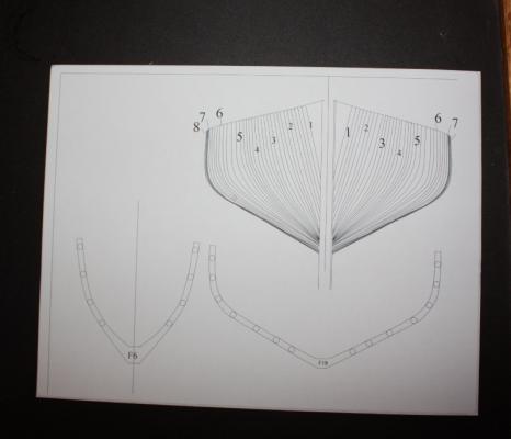
I drew the individual frames based on the body plans. First I aligned the profile drawing that shows the station lines with the framing drawing. I could then identify the frame numbers with the station line numbers which otherwise had no correlation. I had saved the L ofC drawings in TIF so they had decent resolution and could be inserted into a drawing using TurboCad. Once inserted they were checked and adjusted to be sure they were at the proper scale on the drawing. I used the body plan to draw the frames at the station lines which I assumed are correctly shaped on the drawing. I then divided the space between station line frames for the appropriate number of frames between stations (usually four or two). I realize they would probably not be spaced evenly on the body plan in real life, but at this scale and cutting them a tad heavy, they will fair nicely, using the frames on the station lines as the guides. Besides, it was much easier than drafting each frame using the more traditional, and accurate, methods used by many of our friends here. The frames are doubled, each being 6 inches wide (12" total width) and moulded 7 ½ inches. Other than at the floors, the moulded dimension does not appear to change, just remains 7 ½” for most of its height. I used 7 ½” circles along the outboard edge of the frame as guide for placing the circles, then drew the inboard edge of the frames "connecting the dots" and maintaining the line parallel to the outboard line. The frames lie on 24-inch centers, thus there is always 12 inches space between the frames. Rather than building the frames floor and futtock, I used poplar sheets that I planed to 1/8 inch thick. These are glued together with the grain running 90 degrees to each other. Lots of glue, clamps and weights are used to be sure there were no air pockets. Total cost for the wood for the frames was about $35. Had I used Castello boxwood, my favorite, it would have been a much higher cost even if I built the frames futtock by futtock to conserve wood and costs. The doubled frames are still quite strong, even using the softer wood. With the grains running opposite to each other, it easy to see that they are doubled as on the actual vessel. I set the belt sander table to 92 degrees to give the bottom of each frame the angle needed to have them at 90 degrees to the table and account for the 2 degree drag of the keel. I marked the location of each full frame on the keel while laying the keel on the framing drawing. The drawings give no indication of the use of spacers between the frames at the keel or elsewhere, but I will use them regardless to give support at the keel and a rigid frame work. These are all 1/4X 1/4X 1/8. The drawings show that there is a keelson which will add a lot of support as well. A square is used to be sure the frames are perpendicular to the building board as each is raised. Hope some of this makes sense. Allan


- 85 replies
-
- 2
-
-
- schooner
- effie m morrisey
- (and 1 more)
-
Thanks everyone. I will post progress over the next two days, then I'm outta here for a week in Loreto, Mexico with a bunch of friends for some male bonding (aka fishing, beer drinking, poker playing, and alas, a lot of naps now that we are getting a bit long in the tooth.) Allan
-
I have not personally built nor have I seen a fully framed model of a Grand Banks fishing schooner so I thought it would a fun project to try. There is a lot of information available on the Effie M. Morrissey, including a reasonable set of plans that are available from the Library of Congress, she is available to visit in her modern configuration, and there are folks in Massachusetts that have been more than willing to answer questions, so she seemed to me to be a good choice. The following is a compilation of her history from the internet, “so it must be true!” She was designed by George McClain and was the last fishing schooner built for the Wonson Fish Company. She was built with white oak and yellow pine and took four months to complete. She was launched February 1, 1894. Her hull was painted black and her first skipper was William Edward Morrissey, who named her after his daughter Effie Maude Morrissey. She fished out of Gloucester for eleven years then began fishing out of Nova Scotia. In 1914, ownership moved to Brigus, Newfoundland where Harold Bartlett used her as a fishing and coasting vessel along the Newfoundland and Labrador coasts. In 1925 Harold Bartlett sold her to his cousin, Captain Bob Bartlett, an Arctic explorer. Bob Bartlett had an auxiliary engine installed and reinforced the hull for use in the Arctic. In 1926 with financial help from publisher George Putnam , Bartlett began 20 years of exploration using the Effie. When Captain Bartlett passed away in 1946, Effie was sold to the Jackson brothers to carry mail and passengers in an inter-island trade in the South Pacific. On their voyage to the Pacific she developed problems at sea, forcing the crew to return to New York. On December 2, 1947, the boat caught fire while docked at the boat basin in Flushing, New York. The schooner was repaired and sold to Louisa Mendes in Massachusetts at which time she entered the packet trade in a trans-Atlantic crossing to Cape Verde. Upon reaching the islands, Captain Mendes re-registered the schooner under the name Ernestina, after his own daughter, and used her in inter-island trade. Ernestina made a number of transatlantic voyages and fell into disrepair at Cape Verde, where she remained until the late sixties when there was interest in the U.S. to save her. In 1977 the people of Cape Verde made a gift of Ernestina to the U. S. In August 1982 her hull was completely rebuilt and she sailed to the United States. In August 1988 the schooner made a return trip to Brigus, Newfoundland, on the 113th anniversary of Capt. Bob Bartlett’s birth. Ernestina was designated as a National Historic Landmark i with restoration being completed in 1994, and in 1996 became a part of the New Bedford Whaling National Historical Park. She is currently owned by the Commonwealth of Massachusetts. Effie is the oldest surviving Banks fishing schooner; the only surviving 19th century Gloucester-built fishing schooner; one of two remaining examples of the Fredonia-style schooners (the other being the Lettie G. Howard,) the only offshore example of that type; and one of two sailing Arctic exploration vessels left afloat in the United States. This is the fourth model going onto the building board in the attached photos. The model will be based on how she looked in 1894. In the photos you can see that the keel has a piece temporarily attached so it will sit at about a 2 degree angle to match the "drag" and make it easier to check that the frames are 90 degrees to the water lines (building board plane.) I am using Castello box for the keel and deadwood. The plans do not show a shelf along the bearding line of the fore or aft frames. Looking at photos of a rebuild of the schooner Virginia, there are no steps nor shelf. I have no idea if there was one on the original build. More to come, I hope. Allan


- 85 replies
-
- 7
-
-
- schooner
- effie m morrisey
- (and 1 more)