


allanyed
-
Posts
8,141 -
Joined
-
Last visited
Content Type
Profiles
Forums
Gallery
Events
Posts posted by allanyed
-
-
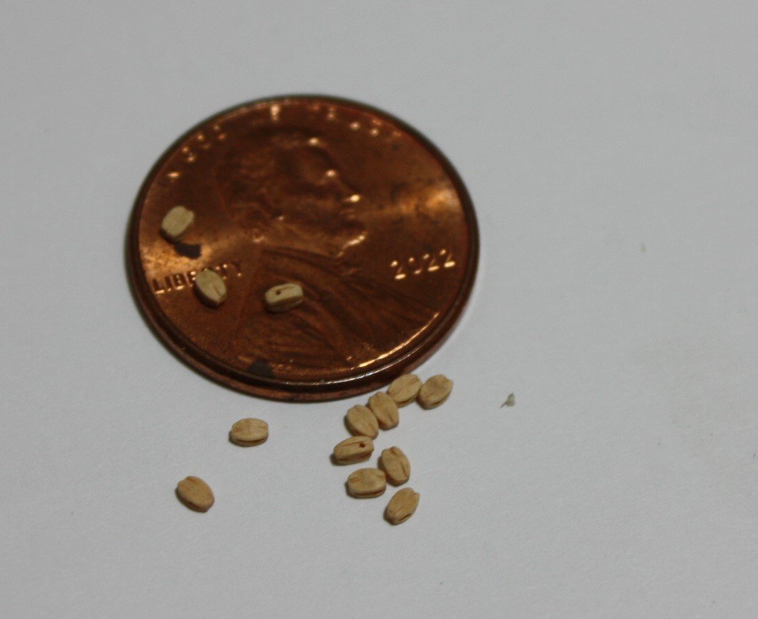
Happy day, I did some digging in my stock of materials and found I still had a number of packages of blocks from Lloyd Warner who owned Warner Woods West back in the day. The smallest I have are 2mm (0.078"), in the pic below but there is room to shorten them a little bit. Goodness gracious these are tiny. The final size I hope to get with a little sanding on the length is 0.065 long so close to the block sizes on the drawing. (0.057X 0.045) The width as they came is 0.051, only 6 thousands oversized compared to the drawing.
Allan
-
Welcome to MSW WD140!!! Glad to see you join up.
Please take a minute to introduce yourself in the new member forum and tell the members a little about yourself.
A moderator may move your post to a more appropriate forum as this one is about how to use the website, not for making requests for plans. There is a forum here called Discussions for Ships plans and Project Research. General research on specific vessels and ship types that might get you some feedback if you post your needs there.
Again, welcome aboard
Allan
-
It appears she was built as the merchant ship Sting in Bermuda then converted to replace the tender, Pickle about 1800. Unless lines were taken when she was brought to England, there may be no existing plans. I agree with you that it might be better to purchase a set of plans from RMG for similar sizes sloops, especially the Lady Hammond which is also a Bermudan sloop and probably built of cedar as was Pickle.
Allan
-
Welcome back to the fray Giovanni.
Allan
- Keith Black and mtaylor
-
 2
2
-
-
Hi Craig,
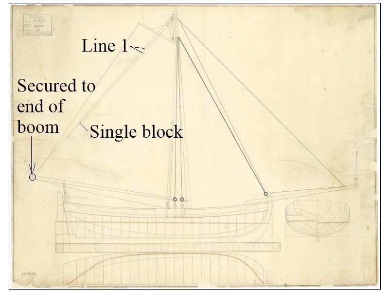
Yes that was my conclusion as well, but as I am not at all sure of the year on that particular plan I opted to go with a wooden jaw on the boom and a support ring on the mast on which the boom end will rest.
Thank you for your input, it is very much appreciated.
Allan
- mtaylor and iMustBeCrazy
-
2
-
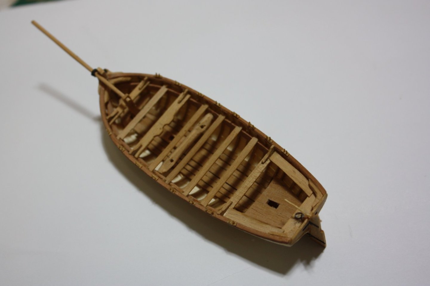
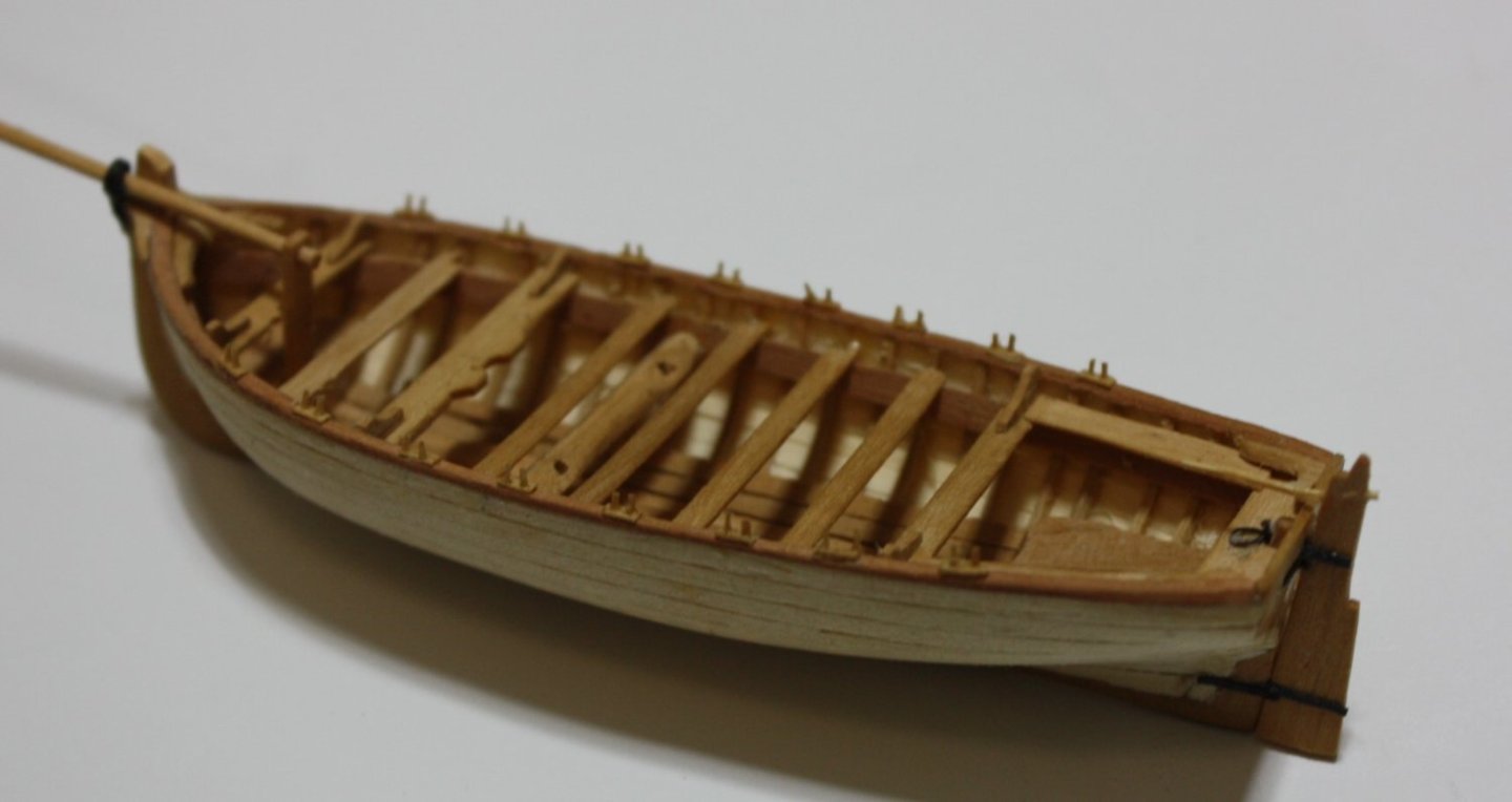
Using the bulkheads in lieu of a full plug is a super idea. Fine looking boat all around! For those without a printer, holly or castello boxwood works well for frames even down to 1:96 (https://modelshipworld.com/topic/35331-31-foot-longboat-1801-by-allanyed-scale-196/#comments post #25
Allan
-
I do have a lathe so may give the brass blocks a try, but my first try will be using European boxwood for the blocks. I have a few small pieces left from the past so will give it a go. Will keep you posted on these as they are coming up very soon.
Mast, boom, gaff and sprit can be seen below. After looking at the photo myself I will be sanding the jaws as they look heavy. On drawing ZAZ7322 it looks to have metal jaw bolted to the mast and a pivot ring on the boom itself. Not sure which would be appropriate for circa 1800.
Allan

- scrubbyj427, druxey, GrandpaPhil and 2 others
-
5
-
Hi Iron Hands
Making the shells is not so bad, but making the sheaves and pins is difficult ------I'm kidding, I left out the pins...........and the sheaves. I am digging out my copies of the McCaffery and McNarry books to refresh my memory on how they did theirs on ultra small scales to see if their methods are applicable.
Allan
- mtaylor, Ferrus Manus and Knocklouder
-
3
-
-
Thukydides,
Your explanation is exactly what I had concluded as well. We are either both correct or not😀
Allan
- mtaylor and Thukydides
-
2
-
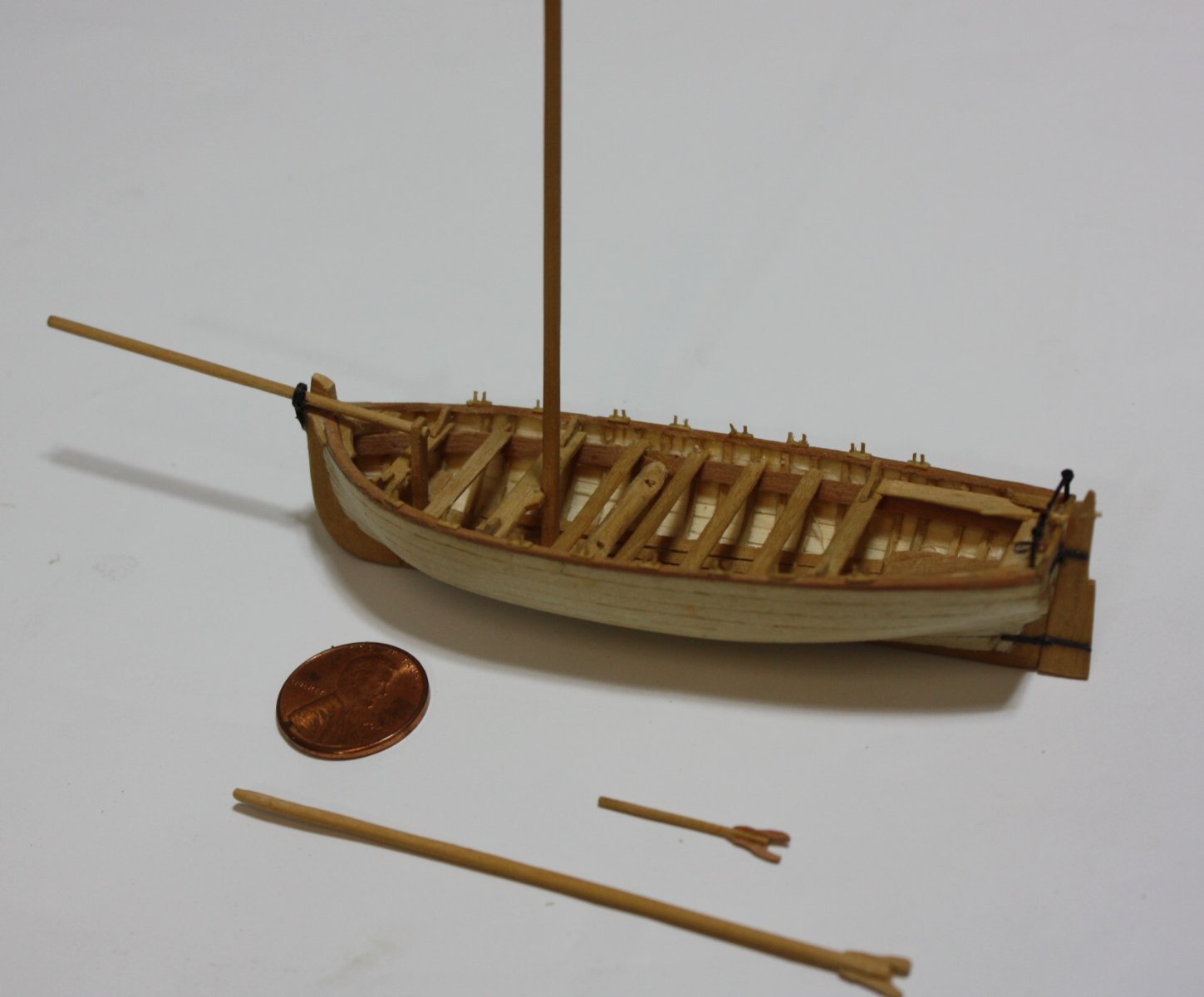
In the meantime, the sprit step post and rudder are in place. The 1.25" broad rudder hinges are so small (0.013") at this scale I used black construction paper rather than brass or copper. If the rudder was to be a hinged properly I would have gone with copper or brass which would surely be doable but I did not see the point of taking on more agita for a static model.
Allan
-
4 hours ago, Thukydides said:
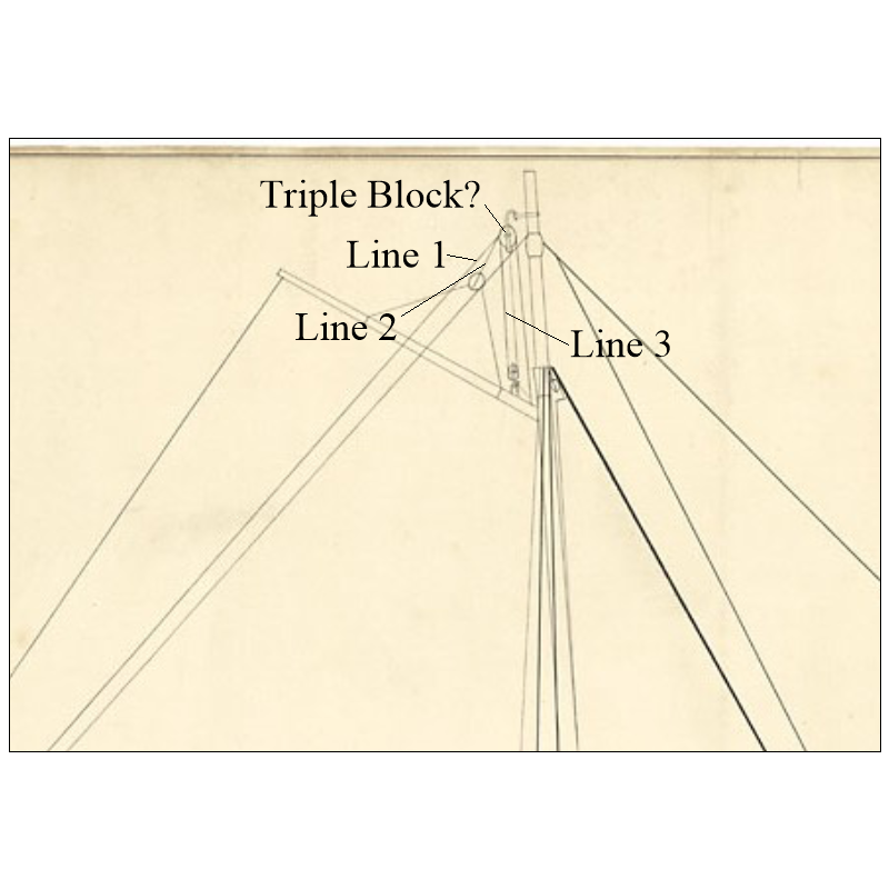
How does it attach to the boom, it it attached to a block or just fastened?
Thank you for your post. I am now a little more confused. Line 1 does not attach to the boom anywhere that I can find. It leads down from the mast to a single block that is attached to the boom then back up and through the upper (triple?) block then down to the deck where it would belay.
Allan
- GrandpaPhil, mtaylor and Thukydides
-
3
-
-
Looking at drawings ZAZ 7322 and ZAZ 5814 I am coming to a conclusion that the deadeyes for the shrouds were hooked to the straps rather than being assembled as on the ship. Am I off base on this? Looking at the Medway longboat model it appears that they are hooked to the straps and have a lashing to keep it secure.
Allan
- mtaylor, Thukydides and shipman
-
3
-
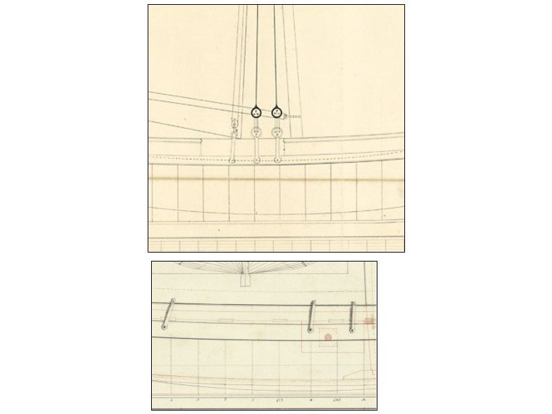
Looking at rigging plans I have a couple items about which I am not sure so if anyone has more information, that would be great.
1. This seems straight forward, but there appears to be a triple block at the top of the mast. I had not seen this before on small boats but maybe it was common. OR, am I not seeing this right?
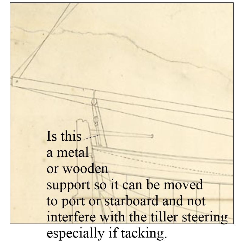
2. This area was recently discussed here at MSW as the sheets could/would foul the tiller. Looking at the drawing more closely, there appears to be something other than a line, perhaps a wooden or metal rod that can be moved from port to starboard as needed. I really have no solution other than moving the lines forward of the tiller.
Another question on a separate post to follow................
Allan
-
Pinstriping tape from automotive stores or the internet works very well. Further to Phil's post #7, if you are painting a stripe that will be bordering on bare wood, spray a clear coat once the tape is on to seal the edges. It will prevent/minimize bleed through when you paint the final color just a Phil explains when using paint to seal the edges.
Allan
- thibaultron, DaveBaxt, Canute and 2 others
-
5
-
Welcome to MSW Geoff!!!
Planking varied in width but the widest portion along a strake was in the range of 10 inches to 12 inches. Look at some contemporary planking plans to see how they tapered. https://www.rmg.co.uk/collections/objects/search/planking expansion drawing
As the taper at the bow was in the realm of half the widest portion midships, using the wider planks makes sense. Once tapered, you still need to shape them as you cannot just glue them in place without having lifting problems. Study the planking tutorial by David Antscherl in the Articles data base here at MSW if you want to learn how to spile planks and if you are going to use strip stock, study the four part video on planking by Chuck Passaro.
Allan
-
-
-
2 hours ago, hollowneck said:
In this photo, located near the tip of a main course yardarm, the violin block works to lift the yardarm (inner, small part) and the larger part (outer) guides a main topsail's tack control rope.
Lees (or me😀) may have this wrong or it may just be a matter of terminology but on page 80 and page 91 of The Masting and Rigging of British Ships of War he describes the larger lower block of the pair, or larger sheave if a fiddle block, as used for the topsail sheet, not a tack. He makes no mention of there being a tack for the topsails.
Allan
-
Hi Bill,
What nation and which lines are you referring to for the long tackle blocks (fiddle blocks)? I cannot speak for earlier dates or nations, but according to James Lees on page 68 of The Masting and Rigging of English Ships of War, fiddle blocks were used from 1719 until 1806. On page 166 he describes them being used on yard arms and where ordinary double blocks could foul up. Regarding those on the yard arm, before and after that period two single blocks were stropped together. Hope this helps
Allan
-
2 hours ago, iMustBeCrazy said:
(assuming the 'hoop' is a flat strap)
Thanks guys
Craig, yes I am going with a flat ring that will be soldered to the arm. The plan I am using is detailed enough that I am sure flat stock would be appropriate for this project. But, the device on the Medway model looks like a rod that was shaped and a small area flattened where the bolt goes through so one can argue either method was acceptable at some point in time.
Allan
- iMustBeCrazy, mtaylor, Knocklouder and 1 other
-
4
-
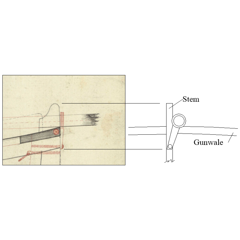
I am having trouble reconciling the shape of the sprit support with ring that allows the sprit to pass on the port side of the stem. There is only one view on the plan so I am guessing using the assumption that simpler is better. I have not yet found another contemporary plan or model that shows the same design detail. I looked at the Medway longboat model at RMG and while it is a bit of a different design it but may be a good alternative.
Any feedback would be most welcome. Thanks!
Allan


31 foot Longboat 1801 by allanyed - scale 1:96
in - Build logs for subjects built 1801 - 1850
Posted · Edited by allanyed
I don't know how he had these made but they are excellent blocks even at that size. He used a hard wood, possibly boxwood, I do not recall, as I have had these since about 2015. There is no char on any of his blocks so I don't think they were laser cut but maybe CNC. Anyone know of any high quality blocks 2mm or smaller? I know Syren makes fantastic blocks but nothing smaller than 3mm unless something has changed.
Allan