


allanyed
-
Posts
8,141 -
Joined
-
Last visited
Content Type
Profiles
Forums
Gallery
Events
Posts posted by allanyed
-
-
Hi R
Welcome to MSW
Allan
- mtaylor and Keith Black
-
 2
2
-
The Bounty launch was about 23' 0" long with a breadth of 6' 9". With this narrow breadth there is a likelihood she was single banked, not double banked as in the posts above.
The Bounty launch model has been discussed in great detail here at MSW based on quite a bit of research by members.
Below is a drawing that may be of help as well as the scantlings for a 23 foot launch that you can compare with the kit to see what you may want to change or add such as the number of frames, and tholes.
The drawing below shows the davit and winch which were likely removed before starting the famous voyage as they would have taken up a lot of space and were of no use anyway.
Allan
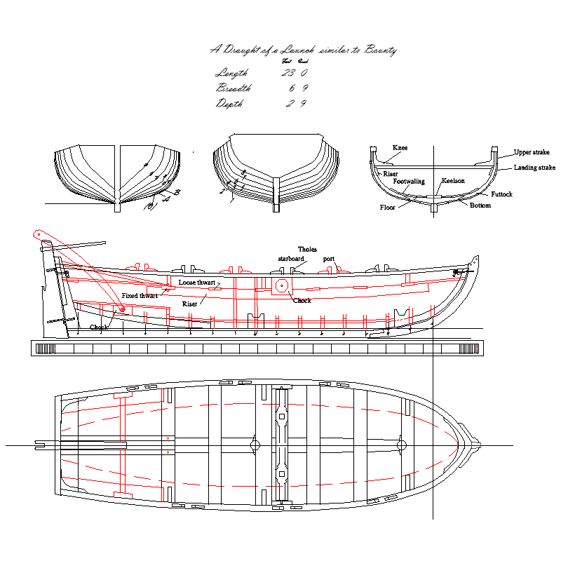
SCANTLINGS
Length 23- 0”
Breadth 6’ 9”
Depth 2’ 9”
Feet Inches
Room & Space 1 2⅜
Stem, sided 3⅜
Keel, Square Midships 3¾
Post sided at the tuck 3⅜
below 2⅞
fore and aft at the keel 8¼
Transom thick 2½
sided 2
Floor timbers sided 2¼
moulded - at the heads 2⅛
-at the throat 3¾
Futtocks sided below 2
square at the heads 1⅞
Keelson thick 2
broad 9½
Footwaling thick 1
Bottom planking thick ⅞
broad 7
Landing strake broad 7
Upper strake broad 7½
Gunwale deep 3
Thick 3¼
Washboard broad at the bow, if included 6
Rising thick 1
broad 5½
Thwarts fixed thick 2
broad 10
Thwarts loose thick 1½
broad 8
Knee on three fixed thwarts sided 3
Benches thick 1½
broad 11
Deadwood sided 3
Breasthook sided 3
length (each arm) 1 10
moulded at the throat 6
Windlass diameter 8
Chocks thick 3
broad 1 1½
up and down 11¼
Ears sided 6
length 1 3
Rudder breadth at the heel 1 4¾
breadth at the hance 1 0
breadth at the head 6¾
thickness 1
Rudder pintle thick ¼
and gudgeon width 1
quantity two
- shipman, Boerscht and Knocklouder
-
3
-
Nate, Depends on the era and maybe the nationality. From James Lees' Masting and Rigging of English Ships of War, pages 2-4 ----The head of the mast was typically left square and did have iron bands and battens. Below the head of the masts, until 1800 there were rope wooldings with a width of 12 inches. There were wooden hoops nailed to the mast at the top and bottom of each woolding. Iron bands replaced the rope wooldings after about 1800.
Allan
- mtaylor, wefalck and Harvey Golden
-
3
-
7 hours ago, Gabek said:
1:64 6-pounder Royal Navy Cannon - George III era
This looks like an Armstrong Frederick pattern (circa 1760-1794) which came about when George was made king. There was also the Blomefield pattern which is quite different but also in the George III era as it was introduced in the early 1790's and replaced the Armstrong Fredericks.
Allan
- Gabek, scrubbyj427, thibaultron and 1 other
-
4
-
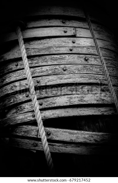
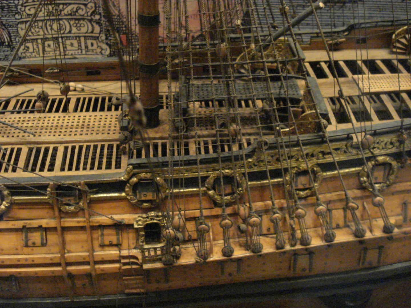
Google Mast hoops and go to images. There are a lot of photos of wooden mast hoops including the one below.
Allan
- davyboy, 3DShipWright and mtaylor
-
3
-
-
14 hours ago, newbee said:
cannons and trucks
I realize this is a terminology thing, but the trucks are the wheels. It sounds like you are referring to the carriages, not just the trucks themselves.
Vanguard makes nice products so you are making a good decision. Looking forward to your return.
Allan
- Bill Morrison and DaveBaxt
-
2
-
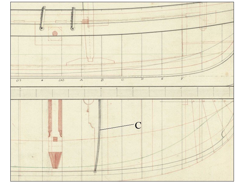
8 hours ago, iMustBeCrazy said:
And so you are a trouble maker Craig, 😀 because she is going to kill me when she asks what I would like from Santa this year.
The rollers fore and aft are indeed another issue as I have no idea why they are there. You mention C. I have posted below what I believe you are speaking about so others are aware of this item. Please correct me if I am wrong.
Thanks for the input Craig, VERY much appreciated! This is one of the most detailed plans I have seen but it has indeed raised questions, including why double lift rings fore and aft. This was a new one for me.
Allan
- mtaylor and iMustBeCrazy
-
2
-
-
Please add my warm welcome to MSW
11 hours ago, RolBerg said:learn to do it the right or best way on my first build.
In light of your very well said comment I am surprised no one has mentioned this, but you may want to consider putting your kits aside for the time being and start with a high quality beginner kit to learn good habits and skills. There is a thread here at MSW on this as well as many build logs of beginner level kits that are well designed with clear instructions and drawings such as the three boat series from Model Shipways.
https://modelshipworld.com/topic/13703-for-beginners-a-cautionary-tale/#comment-421943
https://modelexpo-online.com/Model-Shipways-Shipwright-3-Kit-Combo-Series_p_5465.html
Allan
- mtaylor, DaveBaxt and Keith Black
-
3
-
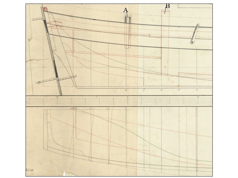
What are pedestals A and B? I can see B possibly being a rest for a boom, but if that is the case, how would it be secured to the boat knowing it will not be in place when not under sail.
The boat is from 1801 and identified in the description at the top of the plan as a 31 foot longboat.
Thanks
Allan
- mtaylor and iMustBeCrazy
-
2
-
Sounds like you are setting up a challenge and I would love to see some take you up on it as I am curious to see the results of other attempts. That scale is a killer for most of us. Hard enough to see things at 1:48 let alone half the size.
Allan
-
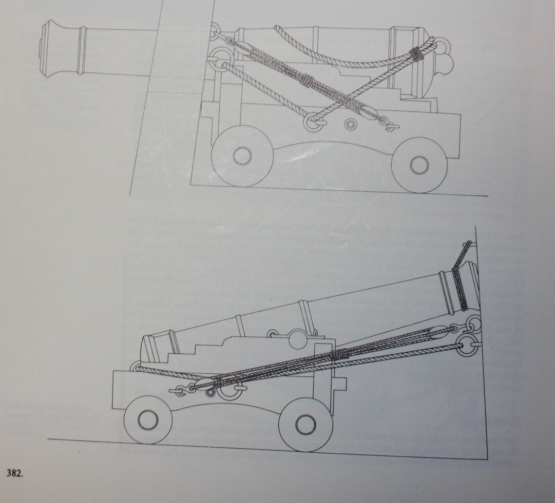
There are drawings of secured guns from Congreve's Treatise on the Mounting of Sea Service Ordnance, Falconer's Universal Dictionary of the Marine and Dupin's Voyages dans la Grande Bretagne that can be found on pages 382-388 in volume II of Caruana's The History of English Sea Ordnance
For secured guns no lines are lying on the deck. Train tackle is of course removed completely and the running out rigging is frapped. The two most common methods SEEM to be a gun run in, secured and housed and at times the guns could be secured run out. The following are from page 382 of Caruana's The History of English Sea Ordnance ISBN 0-948864-22-2 He does not show any drawings where the guns were turned 90 degrees so they faced fore and aft and were secured to the bulk heads. There may be differences for Armstrong Frederick pattern guns and earlier patterns compared to the Blomefields shown below but I suspect they would all be similar with lines off the deck.
Allan
-
59 minutes ago, Sizzolo said:
So in theory if all the planks are cut to the lengths and thicknesses on the plan they should fit correctly on the ship.
The plank expansion plans are extremely useful for dimensional information and supposedly for the shape they show for every strake. This is a question to everyone and anyone: We know planks were spiled to some extent to achieve the shape needed, especially at the bow. But, would there also be some heating and pre-bending in addition to or instead of spiling as needed in areas such as midships, where the bend is less severe and less prone to lifting if edge set. It has been my understanding that these expansion drawings may have been more of a guide rather than a puzzle showing all the pieces and the exact shapes to which they must adhere when being made.
Allan
-
1 hour ago, Sizzolo said:
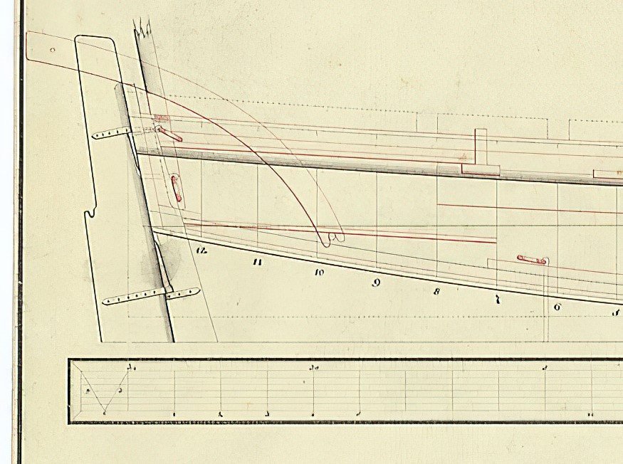
also, the outer works plan is not to scale, likely because of the curvatures involved.
As there is no scale on the planking expansion drawing you can check the distance between station lines on each drawing near midships. If both drawings are the same scale I THINK the distance between stations would be the same. On the profile drawing the distance between station lines is about 1.21". What is the distance from station to station on the outer planking expansion drawing near midships? It's a shame there is no scale on the outboard or inboard expansion drawings of the Diana. I checked some others and found the expansion plans of the Squirrel has a scale so it was apparently not universal to include/exclude it.
Allan
-
It sounds like you have virtually no experience with wooden ships. If that is the case, many folks here will attest to starting small and learning before tackling a more complex model. It seems a major winner in that category is the three vessel series by David Antscherl available from Model Shipways. https://modelexpo-online.com/Model-Shipways-Shipwright-3-Kit-Combo-Series_p_5465.html is one source, there may be others.
You mention wanting a British ship but list Grecian which is American. 😀
Allan
-
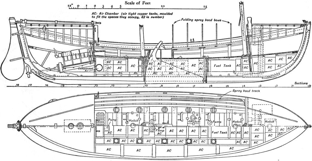
Welcome to MSW George. Is this boat for the steam yacht Greta, 1895 or some other vessel and year? In what country was she built? Finding an appropriate motor driven ship's boat might be a bit easier with a little more information. There are a lot of designs I found on the internet including the one below of a 30 foot boat of 1911 but it may be totally inappropriate in design. If you have not already contacted the folks at the the Royal National Lifeboat Institution, they may have some useful information in their archives. https://rnli.org/about-us/our-history/archive-and-library
Allan
- mtaylor and Mirabell61
-
2
-
Your work looks great to me. I think most/all of us at MSW hope to improve with experience so you are part of a huge team of like minded enthusiasts.
Allan
- dunnock, No Idea, Old Collingwood and 1 other
-
4
-
Nice looking boat!
Maybe something you would like for your files ,boat scantlings PDF is attached below. These are circa 1800 and there were small variations over time so the dimensions are not cast in stone.
From W.E. May
Allan
- mtaylor and Old Collingwood
-
2
-
-
The model you show is really well done and if you want black rope go for it. You can always just get tan rope and stain it with India ink or wood stain. India ink is acidic so wood stains may be better. Hopefully other members will have suggestions of stains that are appropriate. Keep in mind that the ship is fictional and the model they made is not accurate in some respects. For example it shows belaying pins which were not prevalent until much later in the 18th century. In the end, do what makes you happiest, this is a hobby after all.
Allan
-
Dark brown is realistic. IF tarred rope was used it would have been pine resin or something similar and the color would be dark brown, never black. Kits often include black which is not correct in the majority, or perhaps all, cases. 17th century models often had untarred rope on the standing rigging so the era is something to consider. If you are staying with the 18th century rigging, dark brown is the way to go, not black.
Allan
-
1 hour ago, Harry12 said:
Where in the spreadsheet do I put this Allan?
I am pretty sure you have nothing more to do other than start the program by hitting the enter data button at the top, but you put the two dimensions in the first rate box. Your ship is closer to a fifth or sixth rate. I have no idea if the results would actually change.
Long hand using the ratios in Lees
(88+26)/2=57
57/3= 19 so the mast diameter is 19 inches
The circumference of the main stay is 0.5X 19=9.5"
The circumference of the shroud is 9.5X 0.6 =5.7"
The diameter/thickness is 5.7/3.14159= 1.81"
At a scale of 1:48 it is 0.0377" or 0.96mm so 1mm should do well for you if you are building to 1:48 scale.
The diameter for the foremast will be smaller and for the mizzen smaller still. For the foremast most people would not notice if you use the same diameter as for the foremast.
For buying rope, where are you located?
-


Bounty Boat by boerscht - FINISHED - OcCre - 1:24
in - Kit build logs for subjects built from 1751 - 1800
Posted
Totally agree with Keith's comment. There is no need for nails to hold properly shaped planks. They can be held with finger pressure for a minute or so if using PVA or for a few seconds for those using CA glue. Same can be said for filler. If the planks are laid in tight as they should be, no filler is needed. Worst case is to smear a little PVA glue in there SLIGHT gaps and then sand while the glue is wet. The sawdust will fill the gaps and match in color pretty closely for many species of wood,
Allan