


allanyed
-
Posts
8,141 -
Joined
-
Last visited
Content Type
Profiles
Forums
Gallery
Events
Posts posted by allanyed
-
-
As the keel on Hancock was 115 feet 10" long, I suspect there were no more than five pieces. Looking at contracts of 28 gun and 36 gun, British frigates, the keels were made up of four and five pieces. The 74's called out for no more than 6, but they were about 25 feet longer than Hancock.
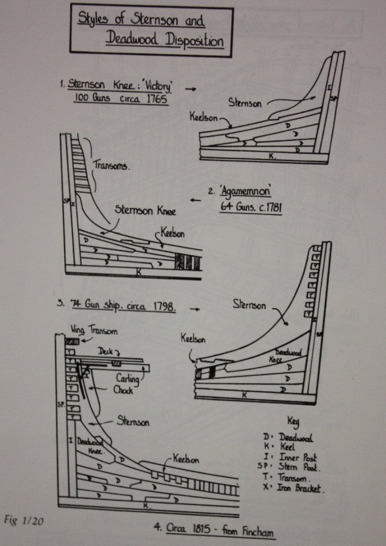
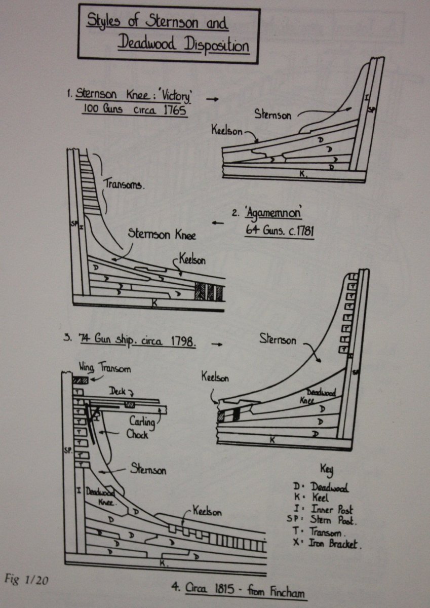
The deadwood aft looks overly complex. Did you get this pattern from a contemporary source? Several patterns from Goodwin's, The Construction and Fitting of English Ships or War, page 29, ISBN 0-87021-016-5 follows. You can see the various dates that may be appropriate to Hancock even if these are British versus USS.
Allan
-
Progress. The windlass was straightforward. Cutting the square holes was really easy with the smallest chisel from Mihail Kirsanov. The thole pins were a challenge and being double banked, twice the fun/grief 😀. I added a plinth/base as Craig described above then drilled holes with a number 80 bit. I was going to use brass or copper wire but there was no way to make them look like wood without paint. I took bamboo down to 0.015" with my Byrnes draw plate then glued these into the holes to represent the pins. They are a tad oversize so had room to flatten to a more square shape using a scalpel.
Allan
-
Somewhere in the past I saw then current photos of the Victory model by Longridge and the planking had a lot of cracks and/or lifting if I remember correctly. Hopefully someone knows where to find the photos and can post them. I seached the net and specifically RMG with no luck.
I have not personally seen it on "modern" models going back to 1978, but you may want to check with a museum expert such as Grant Walker at Preble Hall at the USNA in Annapolis to get their input as they have a vast collection.
Allan
-
19 hours ago, Bob Cleek said:
WELCOME TO MSW
The above is absolutely the best advice. The kits are high quality and you will learn skills that will be used on even more advanced models, be it kit or scratch as you move forward.
Allan
- JBH, mtaylor, Keith Black and 1 other
-
 4
4
-
-
-
Thanks Craig, this is really good stuff.
Allan
- iMustBeCrazy and mtaylor
-
2
-
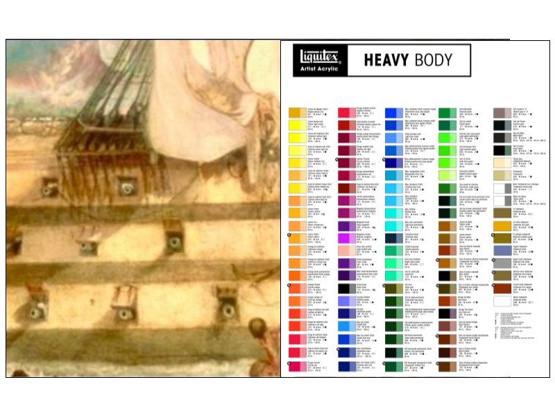
Look at a color chart of a given brand against the painting and you can see what colors are close. If you want an exact match you will most likely need to mix colors to get what you want. The below is how I would start, in this case using Liquitex, my favorite acrylic tubed paint that is easy to find, I also attached a PDF which may be more clear.
Allan
 Liquitex chart against painting.PDF
-
9 hours ago, Roger Pellett said:
At 1:96 scale they are tiny
That's the truth. I just made a couple using 30 gage and it was tricky. I wrapped the wire around a drill bit of the appropriate diameter then removed the "spring" and clipped the rings. How do you make your rings?
Allan
-
13 hours ago, iMustBeCrazy said:
Artist drawings from the mid 1700s and from 1807-8
Thank Craig, this is great information. Can you post or steer me to the later artist drawings? I did look at some [photos of circa 1800 contemporary models of boats and ships with boats and they showed with pins and washboards, or plain pins with no gussets. For the later, they were not clear so could very well have had the 'plinth' Thanks again!
Allan
- Thukydides, bruce d, CiscoH and 1 other
-
4
-
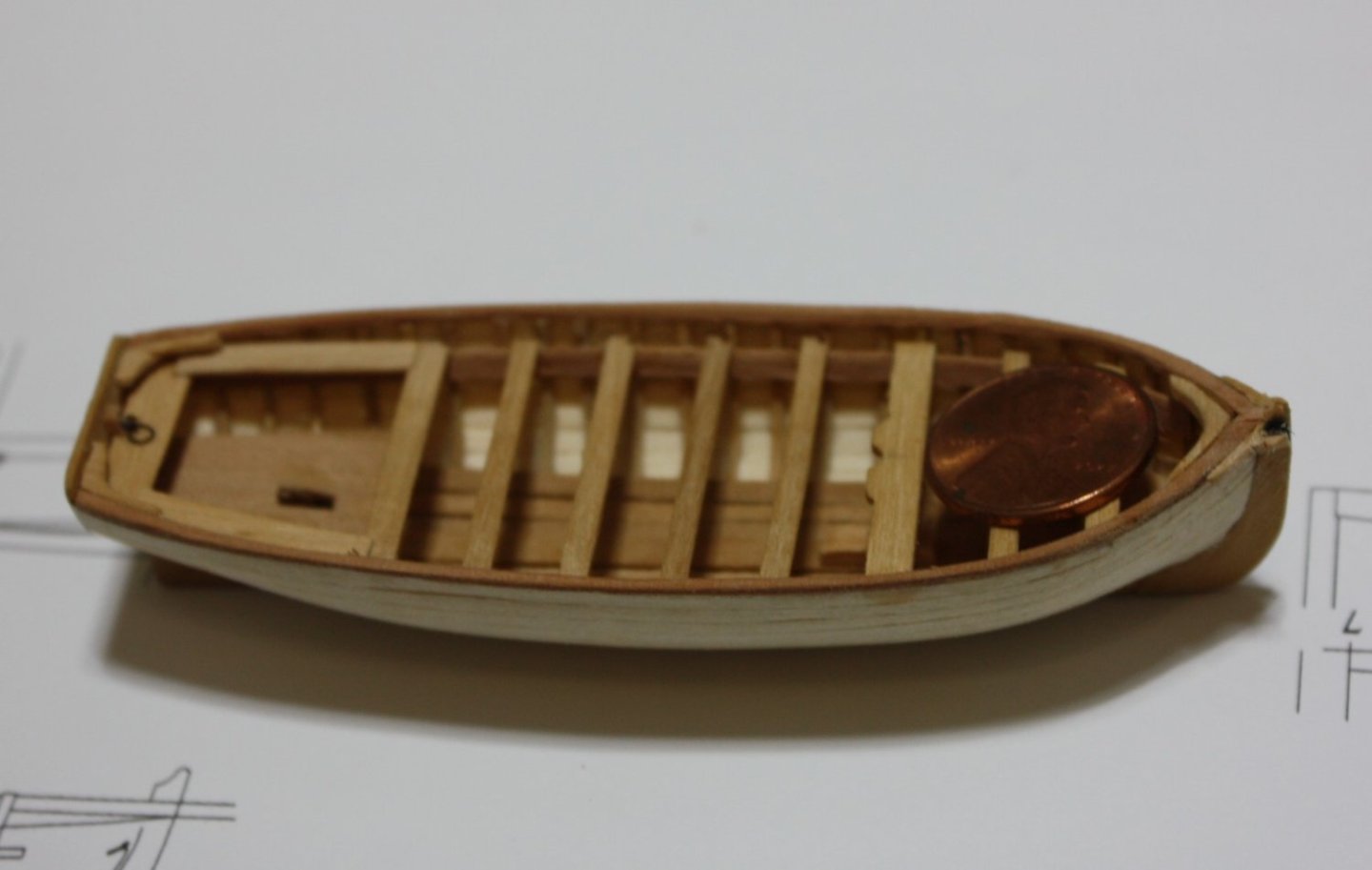
The small pieces are a pain in the neck at this scale, but I am trying.
The thwarts are in, including the fixed thwarts that will receive knees, ears, the benches, transom knees, breast hook, lift rings (32 gage copper wire blackened with liver of sulfur once installed), and the roller in the starboard ear. I cut an opening in the platform aft for a davit arm, but MAY fill it in and add a roller aft as shown on the drawing ZAZ5814.
Question: Circa 1800 what would the tholes for the oars look like? Would they be simple square pins with grooves for wash boards, tholes that are vertical pieces supported with small knees, either of these, or something else?
Thanks
Allan
- GrandpaPhil, shipman, druxey and 7 others
-
10
-
I wonder how much the colors in the painting have changed over the past 200 years. Has the Turner painting been restored or is it the aged original? You can see a lot of restored paintings on the net to get an idea of how much paint color can change over the years for a variety of reasons.
Allan
-
Welcome to MSW David.
Obviously there are no color photos of the Victory in the 19th century so color photos we see are modern era colors. They may be a close match, but maybe not. Also, prints are not necessarily the same as the actual color if you saw the ship in person. Go with what makes you happy but whatever you choose, consider going with high quality artist tubed acrylics, not the bottled craft paints.
Two of the most important differences between craft paints and artist acrylics have to do with pigment content and lightfastness. Artist acrylics have higher pigment content than craft paints, making the colors of artist acrylics more vibrant and deep. Artist acrylics have a higher viscosity than the bottled paints.
The bottled paints are not as lightfast as artist acrylics, which means that they will fade more quickly. By the same token you can protect the bottled paint with a protective varnish, but if you want the colors of your paintings to stay true for many years, go with artist acrylics.Allan
-
Hope to see you again next year (for the Chianti festival in Greve 😀) and see the model in person. It is gorgeous!!
Ciao
Allan
- Keith Black, mtaylor and matiz
-
3
-
-
-
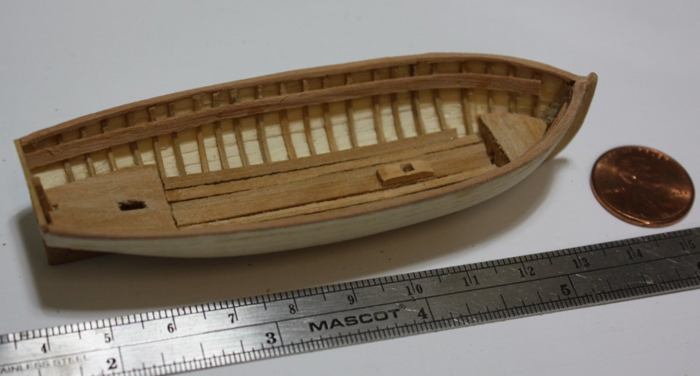
Cap rails (or is this more properly called a gunnel), keelson, foot waling, platforms, risers and mast step in place. To get the risers placed properly I temporarily clamped a 7" (0.073") spacer from the top of the frames to where the top of the riser was to be located.
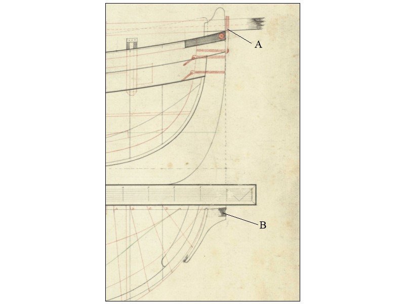
I don't know the name of the piece marked "A" in the plan below, and wonder if the sprit traditionally rested on the starboard or port side of the stem as it did not go over the top of it on the boats. I am pretty sure part A is iron due to the size of the material.
Also, I am guessing that there would be a roller (B) built into both the starboard and port ears, but if anyone has more details, that would be great. Many plans show the ears and I have the scantlings for them but this is the first plan I have seen that shows the roller details.
Allan
- bruce d, iMustBeCrazy, GrandpaPhil and 5 others
-
8
-
11 hours ago, druxey said:
One can wax the plug or cover it in Saran wrap
Thanks Druxey
I thought this might be a good idea, but never tried it with wood. I used to use a mold release wax on fiberglass and gel coat molds when making fiberglass models and it worked very nicely. I will give it a go the next time!!
Allan
11 hours ago, Ferrus Manus said:I can't believe you already finished the planking!
Once I made the holly stock for the planks the right thickness it only took about 15 minutes to make each plank and another few to glue it in place. They are so thin, a scalpel was used for cutting them, including the tapers and a five minute soak in water and one minute blast with a hot air gun shaped them just fine.
Thanks for the comments and likes everyone, they are VERY much appreciated!!
Allan
- bruce d, wefalck and JacquesCousteau
-
3
-
Are you speaking of the Dutch ship from 1628? If that is the ship, there were several decks and each deck would likely have had different beam sizes and different distances between each beam.
If there is an inboard profile drawing or deck plans, these would show the beam sizes and spacing on each deck.
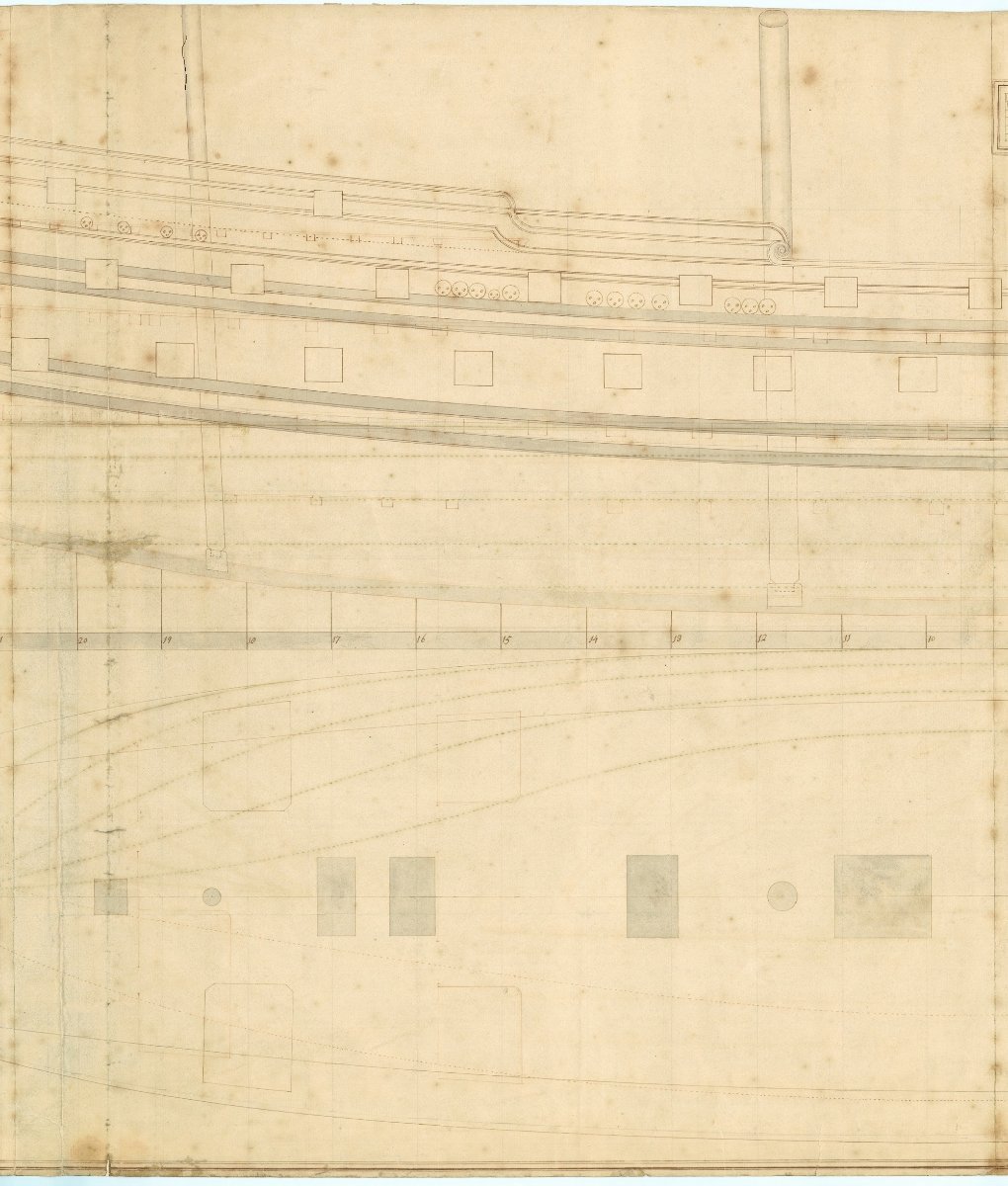
An example is below. It happens to be Antelope (50) 1703 You can see the beams in cross section so can determine sizes and spacing.
Allan
- druxey, scrubbyj427 and mtaylor
-
3
-
2 hours ago, rtropp said:
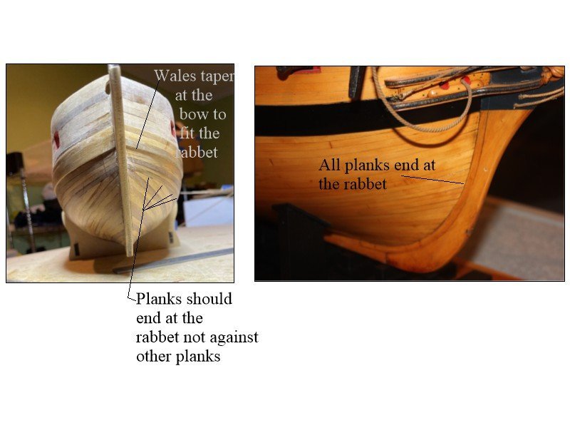
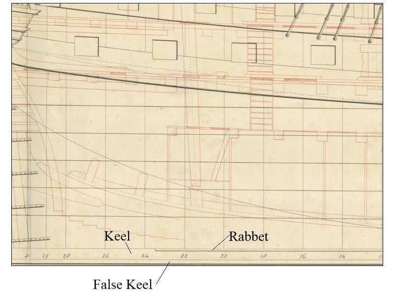
The instructions show that the planks as one piece that run the full length of the boat with the second planking running right up to the edge of the bow, stern and false keel.
The planking does not look like each strake runs up to the bow, but it is hard to see in the photo. The photos below show how the planking ran in reality and how some kit planking is instructed. It does not matter how the first planks run as they will be covered by the second layer but it is great practice to do the first layer the way the second layer should lay if only to learn how to do it.
It seems like the planks in your photo look like they are running as in the pic on the left below rather than the way they were done in actuality as in the photo of a contemporary model on the right.
It is probably just a matter of terminology, but there does appear to be a false keel in the photos you posted. See the second pic below of a contemporary plan.
In the end do what makes you happy, it is your shipyard after all 😀
Allan
-
16 minutes ago, Knocklouder said:
Wow that is thin, how did it not stick to the plug?
The outboard face of the frames stand proud of the plug nearly 0.03 inches so I just had to be careful that the glue was only on the frame and did not get onto the plug when setting a plank in place. The planking went surprisingly fast with little difficulty.
Allan
- mtaylor, Knocklouder, oakheart and 2 others
-
5
-
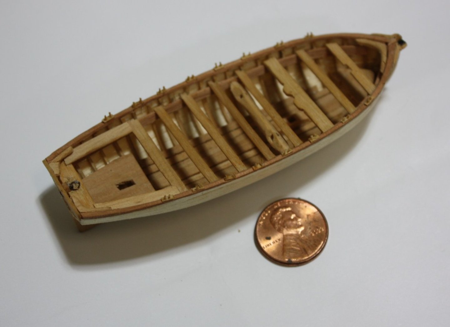
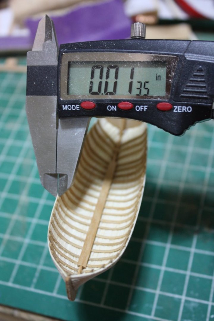
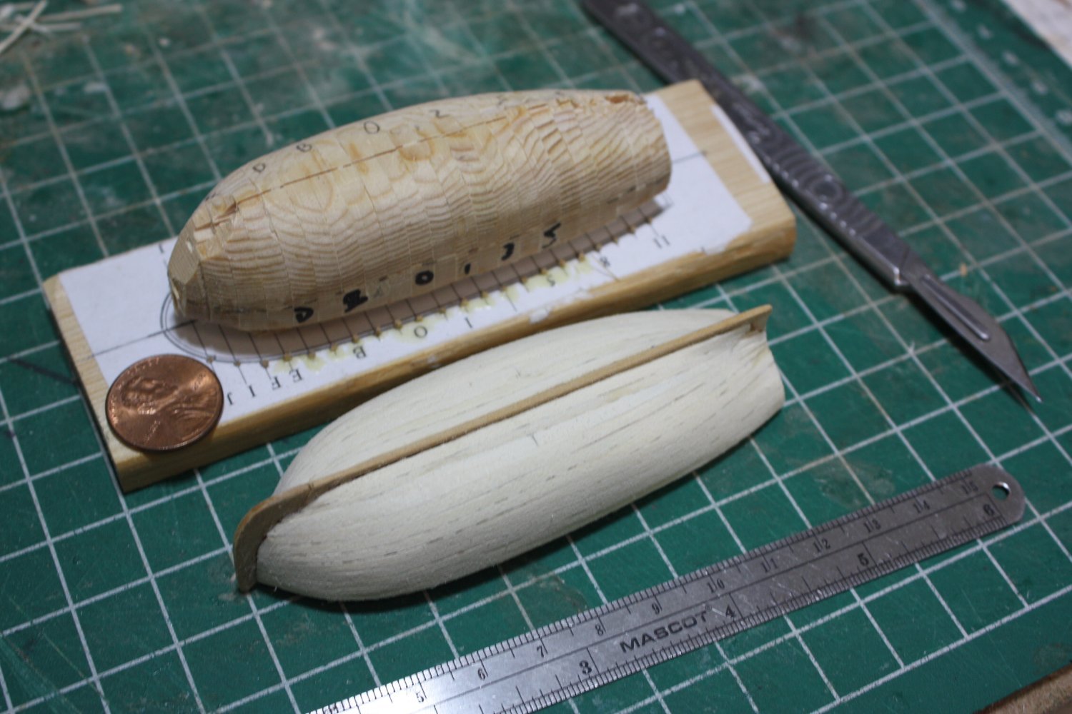
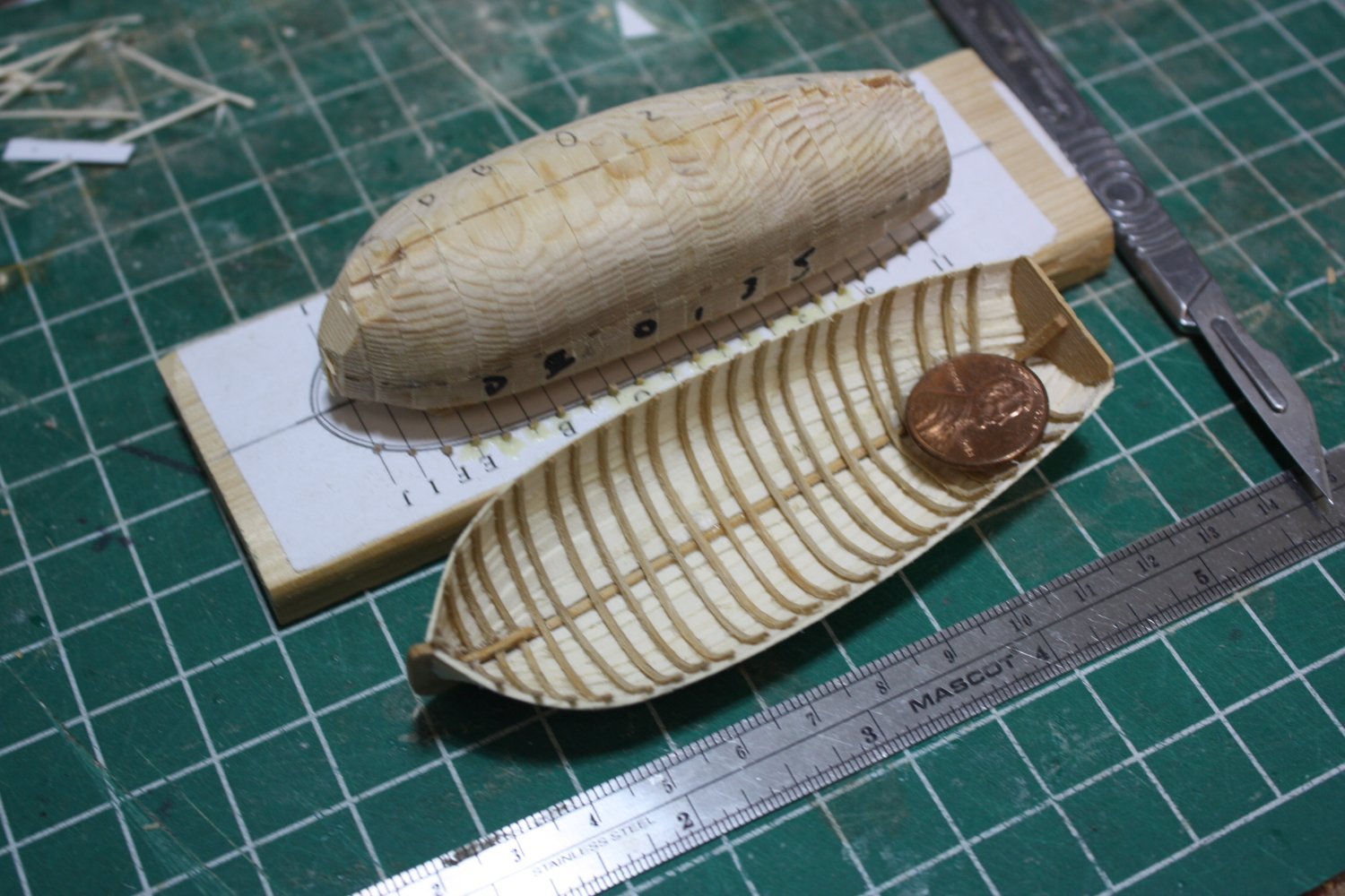
Planking was an interesting endeavor at this scale. The scariest part was when it was time to remove the boat from the plug. Fortunately nothing stuck and it popped off cleanly. I was having trouble putting dots of PVA on the frames before putting a plank in place. If any were even a little too big, it would run off the frame and touch the plug. This would have resulted in the entire boat being glued to the plug. I removed the first strake to be sure and there would have been a mess. I hate using CA, but I went to a CA gel that was very easy to control and it worked.
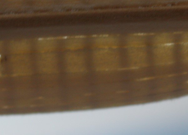
The third photo shows the keelson in place.
As mentioned above, the thin planking is somewhat translucent. This can be seen in the last photo when the boat was held up to the light. Next time I need to be a bit more careful on the spacing of the frames as they vary slightly in a couple cases. They started out perfectly as the guide holes in the base are correct, but when gluing the first planks a couple frames shifted slightly. In the past when building a ship's boat I put spacers between the frames that were shallower than the frames to keep them evenly spaced, but at this scale it was problematic (and I suppose I got lazy.) I know some folks avoid this problem as they cut grooves in the plug, but I have had no luck using this method when it was time to remove the planked hull from the plug.
Allan


- Loracs, GrandpaPhil, JacquesCousteau and 11 others
-
10
-
 4
4
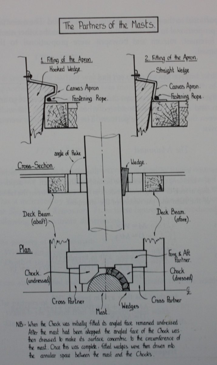
-
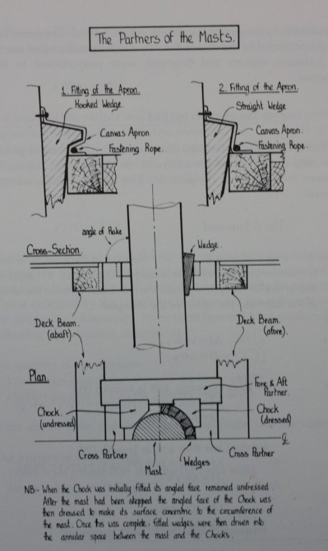
Great questions Tom. As far as I know, the wedges were hammered into place but due to their shape and size of the opening they could not fall through even if they got a little loose. Perhaps they were checked and "reset" on occasion. The drawing below may help. It is from The Construction and Fitting of the English Man of War 1650-1850, page 169 by Peter Goodwin, ISBN0-87021-016-5
Allan
- mtaylor, Dlowder and BLACK VIKING
-
3
-
Welcome to MSW Simon. Wish I could help you but hopefully some members will have built the old Billings kit and be able to offer some help.
Allan
- mtaylor and Keith Black
-
2


31 foot Longboat 1801 by allanyed - scale 1:96
in - Build logs for subjects built 1801 - 1850
Posted
Thanks Shipman. I just took this as a personal challenge to see what I could do. I still prefer 1:48 and am good with 1:64, but at least I know my limits can now include 1:96 within them if the need arises.
Allan