


allanyed
-
Posts
8,108 -
Joined
-
Last visited
Content Type
Profiles
Forums
Gallery
Events
Posts posted by allanyed
-
-
4 hours ago, Gabek said:
If you have diagram with the trough I can easily add it.
Take a look at the drawing above that Ron posted, it should help you. We have been working on a similar project where-in we have 3D drawings of Browne (1625), Commonwealth (1650) Borgard (1716) Armstrong Frederick (1760) , and Blomefield (1791) patterns. Still have a ways to go with Armstrong (1725), additional Blomefields, Pitt, Spanish, and French patterns that are only complete in 2D at this time.
The only noticeable difference between the Armstrong and Armstrong Frederick patterns is that there is no trough on the Armstrong pattern and the cypher is for George 2 rather than George 3. Otherwise, the breech, first and second reinforce, and chase along with the astragal rings are virtually the same based on drawings found in Adrian Caruana's The History of English Sea Ordnance volume 2.
Allan
- thibaultron, mtaylor and Gabek
-
 3
3
-
Hello TJ
According to contemporary information in David Steel's 1805 Elements and Practice of Naval Architecture, the pillars in the hold were not round at that period of time.
Pillars under the orlop beams and gun deck -
13" square along the middle 3/4 of the overall length
At the lower 1/8 of the length they are 16" fore and aft, and 14" athwartships
At the upper 1/8 of the length they are 14" fore and aft and 13" athwartships.
Under the middle gun deck beams, one per beam, 8 inches square at the top and 9 inches square at the bottom.
Under the upper deck 6 inches square at the top and 7 inches square at the bottom except for 2 1/4" square iron pillars at the capstans and galley.
As normal, anything found on Victory today should be checked against contemporary information for the time period the model represents. Many of the details today are different than what she actually looked like at various times of her existence. In the end, your choice. Personally I think the rounded pillars have more character but they may not be realistic if accuracy is a criterion.
.
Allan
- mtaylor, Keith Black and tmj
-
3
-
There are way to make these yourself that will yield nice results. If you do not have an electric drill or lathe, you can make them with separate pieces, square stock and dowel. Drill holes in the square ends to the diameter of the cylindrical piece and assemble. You can also glue flats at the ends onto dowels of the proper diameter then sanding and filling with saw dust will yield nice results as well. Finding these already made to the dimensions you want is unlikely. Perhaps some member here with a lathe will make them for you if you provide a detailed dimensioned drawing.
Allan
- Keith Black and mtaylor
-
2
-
Hi Gabe
Thank you for sharing this. Will you be adding the trough around the vent? Do you or does any member know the vent diameter?
Allan
- thibaultron, Gabek and mtaylor
-
3
-
No matter the printer, draw a test piece with a rectangle that is 5"X 6" or some such dimensions that can be measured with a caliper or other accurate device. Then print it and measure to see if it is accurate. Not all printers are created equal. I always take a caliper to a print shop when I need larger prints. Retail print shops like the old Kinkos rarely got it right the first time but were able to make adjustments. Architectural firms are a better way to go if you cannot get accurate prints at home.
Allan
-
-
Ciao Giuseppe. Welcome to MSW!!!
Allan
- JeffT, Keith Black and mtaylor
-
3
-
On 9/13/2023 at 9:24 AM, Thukydides said:
Tying ropes to endless tiny blocks is maybe not my favorite activity
You could have a lot of company as that is maybe why the master model builders of the 17th and 18th centuries did not always include ordnance of any kind and when they did, rigging the cannon was often left off. 😀
Your photo shows double and single blocks so I was curious if these are all for the cannon? Adrian Caruana points out in his book, The History of English Sea Ordnance Volume II page 386, only 32 pounders and larger had a single and double block set up for both the train and running out tackle. All other calibers had only single blocks. I would not be surprised if there were exceptions, as is often the case for us, for other large calibers such as the 24s to have a single and double.
Allan
- Glen McGuire, AJohnson, Thukydides and 2 others
-
5
-
-
-
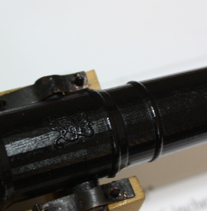
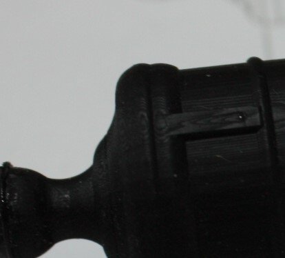
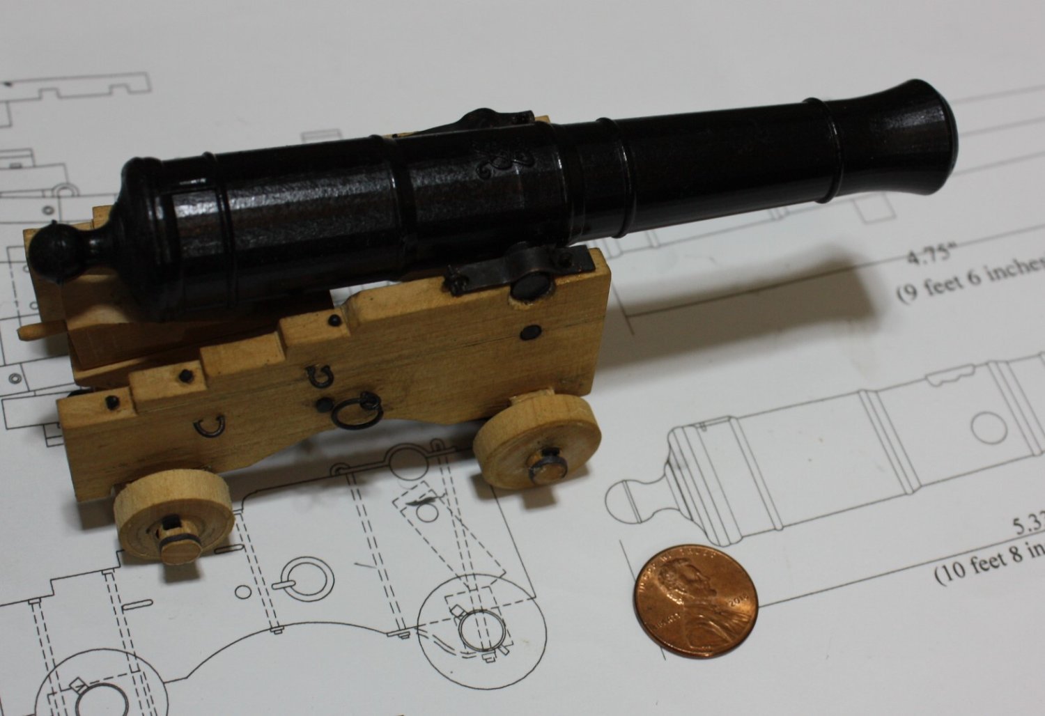
Thanks to fellow member Ron Thibault's work in preparing 3D drawings of the Armstrong Frederick pattern, a realistic barrel was easy to have made. Details of the George III cypher and the flash pan as well as astragal rings can be seen below.
Allan

- westwood, GrandpaPhil, mtaylor and 18 others
-
21
-
Warm welcome to the fray Michael. A motley group we may be, but a more helpful crew you will never see.
Allan
- JeffT, Keith Black, Knocklouder and 1 other
-
4
-
Hi TMJ,
I love the books you mention, but do not diminish the advantages of using contemporary information to confirm or correct modern sources. The AOS series is nice to use as a reference at times but is not without mistakes. The two sites in post #2 should alleviate an excess use of time If you don't mind the low res version- https://www.rmg.co.uk/collections/objects/rmgc-object-80028 will take you right to the cross section drawing of Boyne. I think the high res is better to see how this was all done if you use the Wiki site mentioned above but then again I have old eyes so prefer the higher res plans.😀
Allan
-
TMJ
Which reference books are you referring to? It depends on what period your model is depicting. Iron knees were not used until late in the 18th century so would not have been on Victory when she was launched. If it is from well after she was launched and after her various rebuilds, there would likely have been Roberts iron plate knees used in combination with or possibly in place of timber or possibly later iron plate knees without the side arm. Have you studied any contemporary cross section drawings at RMG Collections or the high res drawings on the WikiCommons site? They show the braces in two views not just the cross section so you can see how they are set up. The drawings of Boyne 1810 and Union 1811 on the Wiki site show the iron knees very clearly as they can be seen in high resolution.
For this high res version go to the Wiki website https://commons.wikimedia.org/wiki/Category:Ship_plans_of_the_Royal_Museums_Greenwich and scroll to Boyne 1810 on page 1, row 9, third drawing from the left. For a low res version of the same drawing enter ZAZ0237 in the search box the RMG Collections site. https://www.rmg.co.uk/collections
Allan
-
Hard to tell from that resolution, but it looks right Mr. Srenner
Allan
-
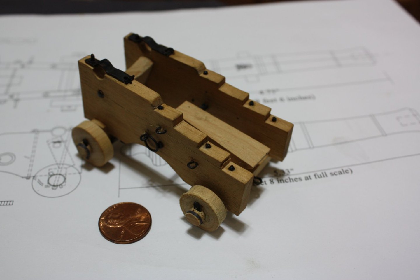
Rings and loops are in place.
Allan
- CiscoH, druxey, scrubbyj427 and 6 others
-
9
-
When there is no super strength required I like to use Solder It paste as it has a melt point of 450F versus over 1200F so your idea should work well.
Thanks Roger.
- mtaylor and thibaultron
-
2
-
Druxey,
Lord knows I have had joints that would not hold because of contamination from fingers, so your point is well taken. Now I will rub my finger on my nose for some oil then apply it to the mandrel before soldering. Easy enough to give it a try the next go around in making these.
Thank you.
Jack
The problem with these ceramic tubes is that they only come in specific sizes. With several gun carriage sizes on many ships and all the scales we use, finding the right size might not be possible for every/any case. I did find a video just now showing turning ceramic on a lathe, so the problem of a fixed number of diameters goes away. A relatively thick ceramic rod turned down for a quarter inch on the end to whatever diameter is needed might just work. Worth a try down the road.
Thanks
Allan
- mtaylor, thibaultron and druxey
-
3
-
Based on the 1719 Establishment the length on the gun deck was measured from the rabbet of the stem to the rabbet of the stern post.
The Ship builder's Repository of 1788 goes further in describing this as from the aft side of the rabbet of the stem to the forward side of the rabbet of the stern post. The 1719 Establishment length of the gun deck for a 20 gun ship was 105 feet so pretty much the same as your metric figure. At scale that is 12.6 inches. Cabins were never not part of figuring ship measurements.
Allan
-
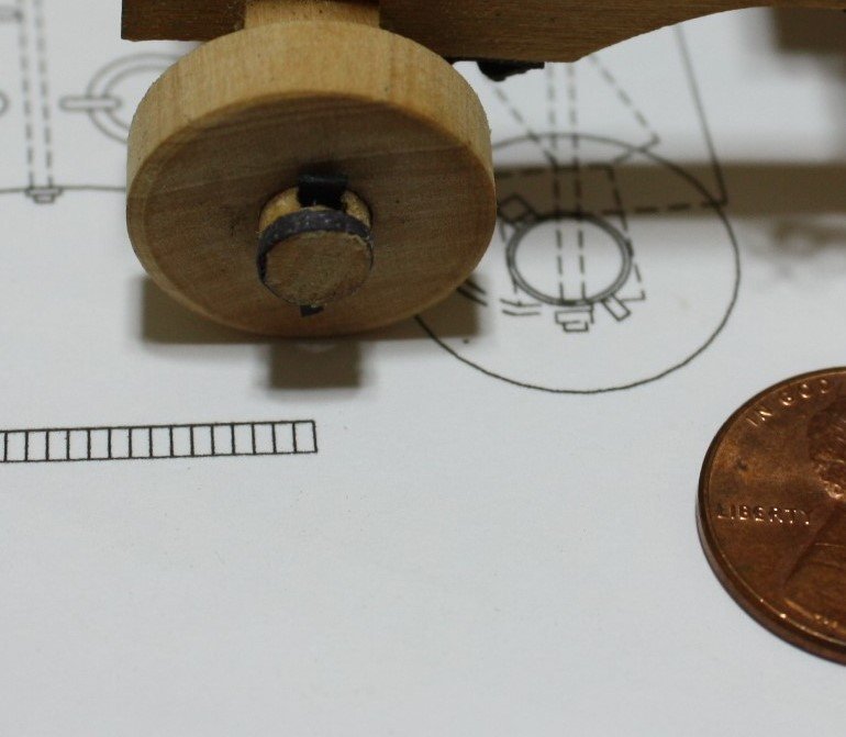
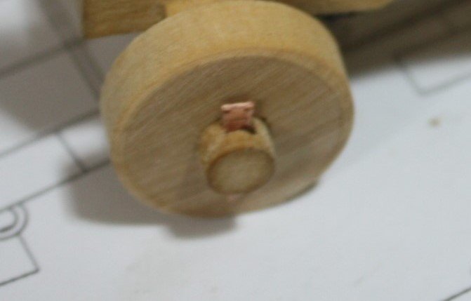
Lynch pins installed and blackened and axletree hoops are in place. The hoops are made from black construction paper. At 1:12 I would give a try at using copper for the hoops, but at 1:24 I failed miserably at my attempts. I might give it another try even at 1:24 in the future but would turn a piece of noncombustible material to the axletree diameter and then wrap a softened piece of copper (or brass) and silver solder it while on the rod. I have no idea if this idea would work or what material to use for the rod so the silver solder would not stick to it.
- mtaylor, oakheart, thibaultron and 6 others
-
9
-
13 hours ago, druxey said:
Try jewelers' supply houses
Thanks Druxey. I did find 40 links per inch brass that our local hobby shop said they can order as well. Thanks again!
12 hours ago, Roger Pellett said:a piece of brass tubing with teeth filed into the business
Thanks Roger. The only problem that may arise is that there are only so many IDs of tubing compared to drill bit sizes to drill the hole in the end of a piece of rod. This can be done without a lathe, but I admit using a lathe is easier.
Allan
-
The many reasons for staying away from used kits for a beginner like yourself are well stated above but you may get lucky like some others have.
On 9/10/2023 at 3:50 PM, Bob Cleek said:Regarding purchasing kits in current production, I think that most experienced modelers would strongly advise you to start your wooden model building learning curve with the Model Shipways Shipwright Series of kits
The above statement is possibly the very best advice in this string. You will learn proper techniques and good habits before moving on to more complex kits or scratch building.
Allan
- Canute, Snug Harbor Johnny and mtaylor
-
3
-
I made the lynch pins from copper sheet then forced into place before blackening as the blackening can be scraped off during this somewhat rough handling. Once in place diluted liver of sulfur is used to blacken them.
Allan
- BANYAN, botra288, GrandpaPhil and 6 others
-
9
-
Many kit makers supply walnut-like wood that is very open grained and looks out of scale even at 1:48. There are more, but these come to mind: Castello box, Swiss pear, bass, and Alaskan cedar are all good choices as they have a tighter grain.
Allan

Hello from West Virginia
in New member Introductions
Posted
Super warm welcome aboard George.
I also love the skipjacks, and built a couple models based on information found at the St. Michaels boat yard and Steve Rogers' book The Skipjack. I was lucky when I last visited the yard as they were rebuilding a skipjack and gave me a piece of the original keel which I cut up and used for some of the parts on the last model.
Hope to see more photos. What you show lucks great!!!
Allan