allanyed
-
Posts
8,149 -
Joined
-
Last visited
Content Type
Profiles
Forums
Gallery
Events
Everything posted by allanyed
-

Split ring making process
allanyed replied to Dave_E's topic in Metal Work, Soldering and Metal Fittings
AH100 and Eberhard With all these small wire sizes, there is no reason to be overscale up to about 1:200 but I cannot imagine making rings at that scale. With these old eyes, I would want to work under a microscope!! Allan -
I like to use this method as well in a number of situations. I have used an iron and hair dryer but find a hot air gun from the hardware store to be easier than a hair dryer or an iron. It gets hot enough to burn wood at the highest control setting so I go to just under that setting and it works really well and quickly. In the end, whatever works is a good way to go and it is nice when we have choices. Allan
-
Scratch built chainplate
allanyed replied to RossR's topic in Metal Work, Soldering and Metal Fittings
What ship/year/nationality? I scoured my books but cannot find a chart so far on the chain link diameters for various size deadeyes, etc, but the following pic from RMG may help you. If the below deadeye was 12" real world the link material diameter would be ABOUT 1.25" so at a scale of 1:85, the diameter of the wire for the links would be about 26 or 27 gage. Give consideration to the shape and lengths of the chain plates as they varied quite a bit as well as the number links when the width of the channels changed a lot around the end of the 17th century and the channels were raised by a deck in the early 18th century. Allan
-
Hi Shipman Just do not use it for ships built from 1670 through 1710 as Danny used his own formula and it is useless for those years. Otherwise it is good to go as it is an easy version of the David Lees formulas used in The Masting and Rigging of English Ships of War, 1625-1860. Go to the articles database in the upper ribbon here at MSW or just click --> https://thenrg.org/resource/articles and scroll down to the spreadsheet by Danny Vadas in the Masting and Rigging section, then click on it and it will open. Allan
- 4 replies
-
- 3
-

-

-
- measurments
- dead eye
- (and 3 more)
-
K, For blocks and deadeye, it as Keith posted. What ship/year/nation? Blocks are sized for the line size which is based on a formula involving mast size, hull size and so on. It is not as hard as it sounds as there is a spread sheet here at MSW that will crank out everything you need once you put in the few initial figures. Same goes for cannon and ship's boats. It depends on the nation, size of the ship and era. If you can indicate which ship, the answers to your questions are not really that difficult to find. Bells varied a bit as well and I for one would love to know if there was a regulation in the past for various nations as there has been for U.S. Coast Guard regs in recent years: §83.33 Equipment for Sound Signals (Rule 33) Allan
- 4 replies
-
- 2
-
-
- measurments
- dead eye
- (and 3 more)
-
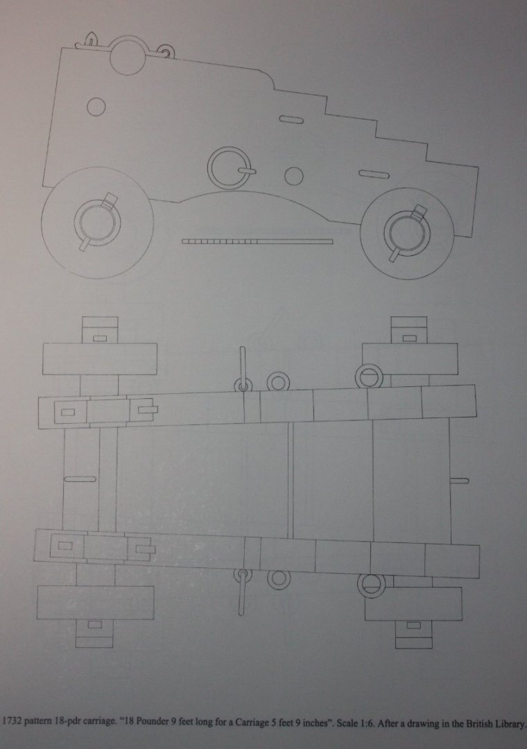
I agree Syren makes beautiful things, including the carriages. It is hard to tell from the photo but the brackets look like they are parallel rather than angled as in the drawing below. From Volume 2 of The History of English Sea Ordnance, by Adrian Caruana, page 373. There are a number of other examples in the book as well. Allan
-
Split ring making process
allanyed replied to Dave_E's topic in Metal Work, Soldering and Metal Fittings
Do you know if they make it in smaller diameters? 0.011 is too large for some rings for scales of 1:64 or smaller. Copper comes in smaller sizes and is easy to solder (soft or silver bearing) and can be blackened with liver of sulfur or painted once cleaned up. Allan -
Jiggling or Nibbling
allanyed replied to CLovehitch's topic in Building, Framing, Planking and plating a ships hull and deck
CH Did you follow up on the responses to this same question that you posted two days ago or do any research of this topic here at MSW? If you use the search box for joggling you will get 9 pages of posts on the subject. Allan -
Ten down, forty to go. Don't even THINK about retiring Chuck, you will disappoint a LOT of folks out there. Congrats!
-
Joggling planks
allanyed replied to CLovehitch's topic in Building, Framing, Planking and plating a ships hull and deck
Hi Clovehitch Do you mean joggling? There are a number of posts here at MSW on joggling the deck planking including (https://modelshipworld.com/topic/21231-uss-syren-1803-by-overworked724-–-model-shipways-–-scale-164/page/16/#comment-791103) as well as detailed drawings in volume I of the Fully Framed Model and The Construction and Fitting of the English Man of War to name two. Allan -
Clovehitch You will KNOT be disappointed for joining the fray here at MSW Welcome Allan
-
The drawings show a platform aft that sits about 15 inches above the keel. Hard to tell if that is the case in your photo. That gives room for the davit chocks that hold the pivot rod beneath the aft platform. There would be a rectangular hole in the aft platform that is large enough for the davit to go through to the rod. Your model is exceptional Craig, kudos!! Allan
-
3D cannon barrels
allanyed replied to allanyed's topic in CAD and 3D Modelling/Drafting Plans with Software
Kevin, PMing you. THANK YOU Allan -
Split ring making process
allanyed replied to Dave_E's topic in Metal Work, Soldering and Metal Fittings
Copper wound around a drill bit as mentioned then cut with scalpel or chisel as also mentioned. Holding the ring with tweezers and using low temp silver solder paste works beautifully. I have been using Solder It Silver Bearing paste which melts at 450F (232C) with great success. A tiny dot of the paste is all that is needed especially with #33 gage copper which would be 1/2" at 1:64. Allan -
Hi Bill, I may be wrong but I don't think the foremast and fore topmast nor the main mast and main topmast and mizzen masts were ever connected this way on a ship, it does not look to be strong enough to hold them together with the weight of spars, sails, and force of the wind. I am pretty sure they would be set up in manner similar to the picture below. The below is from the cover of R. C. Anderson's book The Rigging of Ships in the Days of the Spritsail Topmast 1600-1720 but I would think for the 15th century they would have had something similar, utilizing trestle trees on which the tops rest and a mast cap for support rather than just a rope. I realize this is probably the kit design but hopefully some member will have more information for you and confirm the design one way or another. Allan

-
I have found that the method Roger describes is pretty much full proof. I mark the spot with a fine tip marker pen then use a tiny burr which will get the hole started without wandering. Then all that is needed is to finish the hole with a drill bit. Allan
-
3D cannon barrels
allanyed replied to allanyed's topic in CAD and 3D Modelling/Drafting Plans with Software
As an update, there are now several folks that have offered help in converting 2D to 3D. 2D drawings of 9 and 12 pounder Blomefields in various lengths have been forwarded to them for conversion to 3D. Will continue to update as we move along. Hopefully the full set will wind up covering a long period of time and sizes and benefit scratch and kit builders alike in using appropriate cannon for at least English ships and cover 150 years or more. If anyone has 2D drawings (based on contemporary information,) of French, Dutch, Spanish or other nationalities, these can be added to the mix as well. Allan -
EURYALUS 1803 by Peter6172 - 1:48
allanyed replied to Peter6172's topic in - Build logs for subjects built 1801 - 1850
Hi Peter, Glad I was able to give a little help. I have been using the Veritas Mark II Standard Honing Guide for years with a Japanese wet stone that has two grits. I am guessing many folks have gone to ceramic stones in recent years, so there are a lot of choices. Regarding the Veritas set up, I assume there are other brands with similar designs, but this one has been great for me. IF the edge is in really bad shape with a chip or similar issue I would take it to a professional for the first grinding and sharpening then use the Veritas for maintaining the edge. I do strop with a piece of leather at times and can literally shave hair off my arm after it is honed. Of course a chisel with good quality steel is a key factor. Cheers Allan -
3D cannon barrels
allanyed replied to allanyed's topic in CAD and 3D Modelling/Drafting Plans with Software
Sending you a PM Gray. Thanks! Allan -
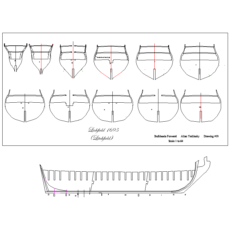
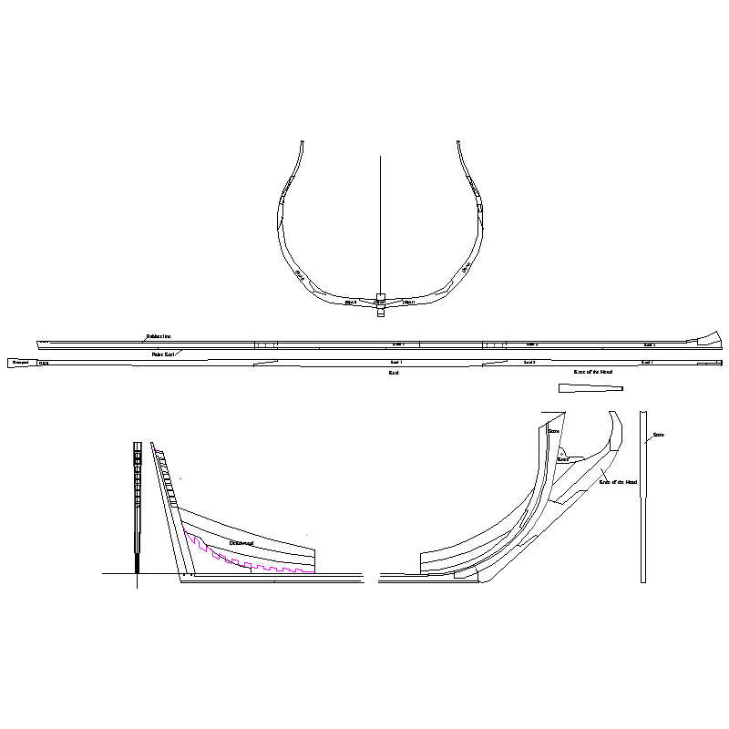
Can you post a picture? You say frames, but it sounds like bulkheads, a totally different thing. Same for the keel. There is the stiff center member to hold bulkheads and there is the keel along with stem, knee of the head and stern post, different animals again. The first pics below are some of the 24 bulkheads for this particular ship with slots for the center member and the center member itself with the keel, stern post, stem and knee of the head. The second is a frame example (there are typically 100 frames +/- and the keel, stem, knee of the head. and stern post and inner post. Allan
-
Your wooden kit progression - go big, or keep learning/practicing?
allanyed replied to Esap's topic in Wood ship model kits
Jaager I think that is still true to a great extent but to me it seems to be to a lesser extent than in years past. Fortunately/unfortunately, depending on an individual's preference, with modern tools for cutting/forming parts, other than the materials, there seems to be a smaller and smaller difference between wooden and plastic assemblies. Examples are laser cut spiled planks and 3D printed parts. No right or wrong, better or worse, just different. In the words of Robert Allen Zimmerman, The Times They Are Changin'. Allan -
Hi Malcolm, I scaled up the drawings of the stern lights of several 17th and 18th century ships and the muntons in nearly all cases were 2" with a few that were 1.25" for upper tier lights. This is major in deciding whether to go with boxwood or an alternate material. I agree that if the scale was smaller and the pieces were 0.01" or so, I would go with styrene strips or some other alternative. Time for more experimenting and considering going back to 1:48 after this project. Life was easier at that scale.😀 Allan
-
Looking for suggestions for a good pin pusher
allanyed replied to Capella's topic in Modeling tools and Workshop Equipment
If you are talking about pinning planking, it is really unnecessary if the planks are properly tapered and pre-shaped by spiling or using the heated edge bend method shown in the four part Chuck Passaro YouTube videos. Consider studying the videos and the planking tutorial in the Articles database here at MSW by David Antscherl. The results from both methods are of the highest order in terms of quality and realism. Allan -
The pram for a starter and rope versus string. Sounds like you did your research. Kudos!!!! Allan
-
Welcome aboard Joe. Beautiful work that you posted! Allan